1
OPERATION AND SERVICE MANUAL
BUS AIR CONDITIONING SYSTEMS
MODEL SERIES EF# AND CS#
OMEGA SPLIT SYSTEMS (EVAPORATOR AND
CONDENSER IN SEPARATE LOCATIONS)
FOLLOW ALL SAFETY AND OPERATION PRECAUTIONS
INSTALLER: REGISTER THE WARRANTY ON LINE AT
WEB SITE www.omega-usa.com
OWNER/END USER: CONFIRM THE WARRANTY
INFORMATION AND ENTER "IN SERVICE DATE" ON LINE
AT SAME SITE.
Failure to comply may void warranty. Maintain Service Records. (See back cover.)
OMEGA ENVIRONMENTAL TECHNOLOGIES
10802 N. STEMMONS
DALLAS, TEXAS 75220
214-357-1795
TOLL FREE 1-888-286-6342
www.omega-usa.com
P/N 57-21002 Revision E 11 07 Available for review on line in PDF format.
Page 1
Limited warranty and warranty disclaimer for Omega Environmental
Technologies, Inc. School and Transit Air Conditioning Systems
Omega Environmental Technologies (OET) hereby warrants its “State of the Art” Air Conditioning System
(“PRODUCT”) to the original purchaser (“PURCHASER”) when installed in a motor coach vehicle
application either in the United States of America or Canada. Warranty offered herein applies only to
defects in workmanship and materials, with the decision to repair or replace parts covered herein to be at
the sole discretion of Omega Environmental Technologies.
Warranty Period
The warranty period starts the day the Omega Product is installed on or in a commercial coach or school
bus. The warranty period is a minimum of 24 months (2 Years). This warranty period applies to the
compressor. The Evaporator and Condenser coils are warranted for 60 months (5 Years). This warranty
period is not limited by mileage or operating hours.
Warranty Coverage
This warranty specifically covers all major components of the product either manufactured by, or under
the specifications set forth by OET, such as but not limited to, compressor, evaporator assembly and
condenser assembly. The cost of replacing the refrigerant is covered only if the loss of refrigerant was due
to a defective part covered under warranty. Any item repaired or replaced under warranty will remain
under warranty until the end of the original warranty period, or for 90 days for the date of repair or
replacement, whichever is longer.
Items Not Covered By Warranty
Omega Environmental Technologies products improperly installed, modified in any way, without prior
written approval from OET, disassembled or tampered with by anyone other than OET, and products
damaged by misuse, negligence, abuse, accident, corrosion, fire, water, vandalism or explosion are excluded
from warranty. Product damaged by the original purchaser or any other third party, including a vehicle
dealer or service facility while performing work, is not warranted by OET. Service items requiring either
replacement or adjustment such as but not limited to filters, belts, lubricants, etc. are not covered under
warranty. This warranty does not apply to any OET system or replacement product not properly serviced
according to the manufacturer recommendation and/or specification. Any cost incurred by the purchaser
including damage to or loss of vehicle, or any part thereof, for transporting the vehicle to an OET dealer or
authorized service center, loss of time or operating revenue or cost of using an alternate replacement
vehicle is not covered. Product failures as the result of an act of God, such as, but not limited to, lightning,
earthquake, windstorm, tornado, hurricane or flood are not covered. Omega Environmental Technologies
reserves the right to improve future product design, without retrofitting existing products in the field to
match the new specifications.
Obtaining Warranty Service
To obtain warranty service for Omega Environmental Technologies units, the product purchased must be
returned to any authorized OET distributor or service center. All warranty claims must be within the
warranty period. Any person applying for warranty service shall provide proper documentation that they
are the original owner and the date warranty commenced.
Complete Warranty
The warranty described in this document is the complete warranty for this product and is in lieu of all
other warranties, either expressed or implied, including without limitation any implied warranty of
merchantability of fitness or ability to successfully perform a specific purpose or job application. OET
hereby waives any obligation, liability, right, claim or demand in contract, tort (including negligence), strict
liability, patent infringement, or otherwise with respect to the OET product furnished.
Authority To Change Or Modify
The warranty described and defined herein can only be changed or modified by Omega Personnel. This
includes all terms, conditions, limitations, rights or obligations. Should OET offer a different warranty in
the future, it shall only apply to products sold when in effect, and the terms. Conditions, and limitations of
this warranty will not be transferable or subject to upgrading.
Version 001 03/23/1999
Page 2
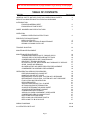
Click on the sections below or page number to go directly to that page
TABLE OF CONTENTS
SECTION
Page Number
GENERAL SAFETY NOTICES, FIRST AID, OPERATIONAL SAFETY
SERVICE and MAINTENANCE CAUTIONS and WARNINGS
4
4
INTRODUCTION
FROM ENGINEERING DEPT
FROM SERVICE PARTS DEPT
6
6
MODEL NUMBERS AND SPECIFICATIONS
7
OPERATION
NORMAL OPERATING INSTRUCTIONS
8
PREVENTATIVE MAINTENANCE
NEWLY INSTALLED
PERIODIC AND SCHEDULED MAINTENANCE
SPRING CLEANING CHECK LIST
9
10
11
TROUBLE SHOOTING
12
MAINTENANCE EQUIPMENT
15
MAINTENANCE PROCEDURES
COMPRESSOR MOUNT BOLTS TORQUE SPECS
TORQUE SPECS FOR REFRIGERANT FITTINGS
COMPRESSOR DRIVE BELT MAINTENANCE
DRIVE BELT TENSION GUIDELINE
RETURN AIR FILTER, RELAY BANK AND THERMOSTAT SERVICE
ODOR, CAUSE AND REMOVAL
BLOWER MOTOR AND SPEED RESISTOR REPLACEMENT
CONDENSER FAN ASSEMBLY REPLACEMENT
16
16
16
17
17
17
17
18
18
REFRIGERATION SERVICE PROCEDURES
PREPARING MANIFOLD GAUGE SET
MANIFOLD GAUGE SET USAGE
REFRIGERANT LEAK CHECK - SYSTEM WITH PRESSURE
REFRIGERANT LEAK CHECK - SYSTEM WITH OUT PRESSURE
EVACUATION AND DEHYDRATION
RECOVERY NOTES
ADDING REFRIGERANT FULL CHARGE
OPTIMUM CHARGE DETERMINATION
CHARGE DETERMINATION WORK SHEET
ADJUSTING REFRIGERANT CHARGE
COMPRESSOR REPLACEMENT
ADDING OIL WHEN COMPONENT IS REPLACED
COMPRESSOR OEM OIL AMOUNTS LIST
REPLACING RECEIVER DRIER
REPLACING HIGH PRESSURE SWITCH
REPLACING TXV BLOCK VALVE
18
19
19
19
20
20
21
21
22
23
24
24
25
27
27
27
27
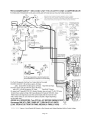
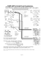
WIRING DIAGRAMS
28-32
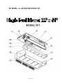
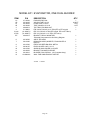
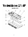
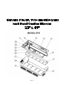
ILLUSTRATED PARTS LIST
33-46
Page 3
SAFETY
GENERAL SAFETY NOTICES
The following general safety notices supplement the specific warnings and cautions appearing
elsewhere in this manual. The recommended precautions, cautions and warnings must be
understood and applied during operation, service and maintenance of the equipment covered
herein.
FIRST AID
An injury, no matter how slight, should never go unattended. Refrigerants can cause damage to
skin and eyes. Always obtain first aid or medical attention immediately in the event of an accident.
OPERATING SAFETY PRECAUTIONS
Keep hands, clothing and objects clear of any moving components, including evaporator blowers,
condenser fans, and compressor drive belts and pulleys. Beware of unannounced starting of
evaporator blowers, condenser fans, or compressor clutch engagement.
In case of severe vibration of unusual noise, stop the system, report to maintenance dept, have
service performed by qualified personnel.
When A/C system is operating, the high side pressure components, fittings and lines or hoses will
be hot enough to burn skin. Do not attempt to touch or grab onto these components either during
or thereafter until they have cooled. High pressure lines, hoses, etc. are not to be pulled on or
"wiggled" while they contain pressure or premature failure might occur. Same applies to low side
components except they are cold during operation. If a leak were caused by disturbing either, then
the temperature will drop INSTANTLY and may cause bodily harm.
If suspicious smell perceived, like hot or burning materials, then immediately, turn off any switch
associated with problem system and do not try to re-operate. Tag or tape off any controls, have
system diagnosed by qualified personnel.
Do not bypass any electrical safety devices. Do not simply reset or bridge any overload device,
properly diagnose with ohm meter and ampere meter. Do not use any sort of jumper wire in any
electrical circuit.
CAUTION: Avoid breathing any refrigerant vapor or lubricant vapor. Exposure to these, especially
PAG oil mist, may irritate your eyes, nose, or throat.
SPECIFIC CAUTION: DO NOT ALLOW OILS TO DRIP INTO OR ON PLASTIC DRAIN PAN OR
ANY PLASTIC PART OF THESE SYSTEMS AS MATERIAL WILL ABSORB AND BECOME
BRITTLE AND PRONE TO CRACK. USE ONLY APPROVED CLEANERS OR MILD SOAP AND
WATER TO CLEAN ANY PLASTIC COMPONENTS.
WARNING: In case of electrical fire, extinguish with CO2, DO NOT USE WATER. Turn off
system. Disconnect the battery ground cable if at all possible. Do not risk injury to save
replaceable machinery.
SERVICE AND MAINTENANCE PRECAUTIONS and WARNINGS
All operation safety precautions apply.
SPECIFIC WARNING: Do not oil blower motor shaft if replacing plastic wheel, clean shaft of
any oil present. Replace spring clips with new part.
Page 4
SPECIFIC CAUTION: Do not allow oils to drip into or on plastic drain pan or any plastic part
of these systems as material will absorb and become brittle and prone to crack.
USE THE CORRECT TYPE OF REFRIGERANT and OIL LISTED FOR A/C SYSTEM. Always
wear protective eye wear and gloves when working with refrigerants and oils.
Always use mineral oil to lubricate O-rings and threads of fittings. CAUTION: Always wear gloves
when working with PAG or Ester oils as to prevent irritation of skin. WARNING: These oils can also
damage vehicle paint, plastic parts, engine drive belts and rubber components like coolant and
vacuum hoses. PAG oil will absorb moisture and become very acidic and corrosive.
CAUTION: Follow hose and fitting manufactures recommendations for replacing hose end fittings.
Oil is to be wiped cleaned from inside and outside of end section of hose for Bead-Lock style
fittings. For E-Z Clip, oil the fittings nipple (mineral oil on o-rings).
Familiarize yourself with the proper operation of any service equipment you will be using. Always
follow manufactures instructions for recovery/recycling equipment. Failure to do so could cause
personal injury or damage to the equipment. Consult any manual or authorized service center prior
to repairing any equipment. Always unplug unit before attempting any maintenance. Removing
internal fittings and filters can release pressurized refrigerant. Slowly release any pressure and
wear appropriate safety gloves and eye protection.
CAUTION: Use only Department of Transportation (DOT) approved cylinder for storing used or
recycled refrigerant. Approved cylinders are stamped DOT 4BA or DOT 4BW. Store in approved
cooler locations, avoid heat. WARNING: High heat can raise internal pressure to dangerous levels.
US law requires certification for use and handling of refrigerants. The use only UL approved heat
blankets to raise the pressure of cylinder to aid transfer to system during charging. Do not leave
unattended or plugged in for more time then is required to perform service.
CAUTION: Never use compressed "shop" air to leak or pressure test an A/C system. Under
certain conditions, pressurized mixtures of R134a and air are combustible. In addition shop air will
inject excess moisture into the system.
CAUTION: Do not use open flame around refrigerants. Avoid combustion engine operation when
refrigerant leak is detected near intake area. If accident occurs leave area immediately.
WARNING: DO NOT BREATHE ENGINE EXHAUST OF COMBUSTED REFRIGERANT FUMES.
CAUTION: Turn off switches and disconnect battery ground cable when working on electrical
motors, controls, or if shorting with tool is even a remote possibility.
CAUTION: Completely disconnect battery if arc welding on vehicle!
CAUTION: Even if someone has told you what is wrong with an A/C system always perform a
visual inspection prior to connecting gauge set. If there is any chance that someone has used the
wrong refrigerant or failed to evacuate system then fully dehydrate and recharge with correct
refrigerant to avoid personal injury due to unpredictable high pressures developing in system.
CAUTION: Nitrogen to be used with pressure regulator only. Normally set a 125 psi or less, 250 psi
maximum. DO NOT EXCEED NORMAL OPERATING PRESSURES DURING ANY SERVICE
PROCEDURE!
WARNING: Do not use oxygen in or near refrigeration system as explosion may occur.
WARNING: Serious damage results when liquid refrigerant is sucked into the compressor.
Exercise caution when adding refrigerant to suction side of system.
Page 5
INTRODUCTION FROM OMEGA ENGINEERING DEPT
Routine maintenance of return air filters, compressor drive belts tension, condenser fins and
fans will greatly enhance the cooling performance of these A/C systems. The service issues that
place a refrigeration service mechanic in a separate category are addressed in this manual in a
separate section. Basic understanding of vapor compression refrigeration cycle is essential. Most
all refrigeration service relies on the basic principals for proper diagnosis and service procedures.
Although this manual is not intended to be a basics text, it does cover a lot of basic service
information that is worth review. You will also find specific service recommendations, specifications
for OMEGA bus systems as well as some unique excerpts based on field experiences from our
staff. Hopefully operators, service writers and mechanics will all read pertinent sections. We
especially invite everyone to read the trouble shooting section and find it both entertaining as well
as informative.
The number one failure, in terms of difficulty, is locating the leak that has caused the loss of
refrigerant from today's A/C systems. Locating leaks is now more difficult with R-134a and the
synthetic oils required then it was with R-12. First off, the R-134a molecule is smaller and more
"slippery" than R-12. Secondly PAG and Ester oils evaporate, thus the tell tale oil of a leak may or
may not be found. Leaks in coil bodies are extremely rare, however leaks at brazed joints do occur
and when the coil is encased or shrouded finding the leak can be quite a challenge. GOOD LEAK
DETECTION DEVICES ARE REQUIRED. OMEGA HIGHLY RECOMMENDS THE ADDITION OF
UV DIES TO ASSIST IN LOCATING LEAKS.
The number one failure in terms of difficulty to diagnostic is or can be electrical problems. Once
more the basic principals are not covered in this manual. What is provided is clear and concise
wiring diagram(s) for the systems we manufacture. We use ground switching exclusively for
controlling relays for blower speeds because of the inherent safety in avoiding shorts in the control
circuits and to minimize voltage drop in long run feed wires. Using this technique also relieves the
blower switch from having to carry high blower current and thus only milli amps pass through the
switch to control the relays. OMEGA does provide installation training and strict guidelines for
installation of systems. However systems are installed in an after-market forum and installation
centers are responsible for the many details involved in each application. You may find subtle
differences in small things like pressure switch location or hose and wiring routing etc.
We offer the following tips. A simple test light may be used for ground switching diagnostics in
some cases by putting the clamp lead to a known positive battery source. However the test light
approach may fall short if voltage drop due to current load or corrosion is the issue. Good
grounding is just as important as supply voltage as it completes the circuit. We strongly
recommend that each system be thoroughly checked when new. Make note of install particular
voltage drops and current draws. Our tip is to use a black marker and simply write the numbers on
the major component (on the metal inside the evaporator cover) and on the wiring diagram of this
manual that should stay with the bus and/or kept on file for the fleet.
INTRODUCTION FROM SERVICE PARTS DEPT
In the following pages and at the end of this booklet you will find part numbers for service items
and replacement parts for the OMEGA Bus Systems. We hope you never need to replace a single
component, however we know that hard working fleet units accumulate run time hours rapidly and
A/C systems require maintenance and service as a result of demanding operating environments.
PLEASE NOTE THAT A LOT OF THE COMPONENTS ARE GENERIC (INDUSTRY WIDELY
USED) ITEMS AND ARE THEREFORE AVAILABLE WITH CROSS REFERENCE TO OTHER
MANUFACTURES UNITS. WE INVITE YOU TO CHECK WITH OUR KNOWLEDGEABLE STAFF
FOR ALL YOUR REPLACEMENT PARTS NEEDS. WE PRIDE OURSELVES IN PROVIDING
QUALITY PARTS WITH RAPID SERVICE.
Page 6
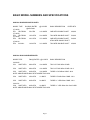
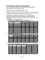
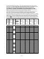
BASIC MODEL NUMBERS AND SPECIFICATIONS
SCHOOL BUS EVAPORATOR UNITS
MODEL TYPE
BLWR(S) RATED
@zero static
27-19522
EF1
FB F/R/SM
27-19520
EF2
FB F/R/SM
27-19526
EF3
FB F/R/SM
27-42014
EF4
IN-WALL
@13.5VDC
BASIC DESCRIPTION
RATED BTU
750 CFM
14.2 AMPS
ONE MTR/ DOUBLE SHAFT
40,000
1150 CFM
22.4 AMPS
TWO MTR/ DOUBLE SHAFT
52,000
1315 CFM
37.2 AMPS
ONE MTR/ DOUBLE SHAFT
&TWO MTR/ SINGLE SHAFT
54,000
1140 CFM
31.2 AMPS
TWO MTR/ DOUBLE SHAFT
45,000
SCHOOL BUS CONDENSER UNITS
MODEL TYPE
FAN(S) RATED @13.5VDC
BASIC DESCRIPTION
24-30105
CS1
SKIRT MTG
2490 CFM
18.4 AMPS
TWO 14" FANS 2Row COND
CS2
2280 CFM
18.2 AMPS
TWO 14" FANS 4Row COND --NLA
SKIRT MTG
CS3
SKIRT MTG
2950 CFM
18.5 AMPS
THREE 11"HD 6Row COND --NLA
NOTE: ABOVE MODEL MAY BE STACKED TWO HIGH
CS4
SKIRT MTG
1930 CFM
12 AMPS
THREE 9" FANS 4Row COND --NLA
CS5
SKIRT MTG
2950 CFM
26 AMPS
THREE 11" HDP 6Row COND --NLA
24-41531
CS6
SKIRT MTG
2950 CFM
26 AMPS
THREE 11" HDP 4Row Sub-Cool COND
NOTE: ABOVE MODEL MAY BE STACKED TWO HIGH
Page 7
OPERATION
See Operation Safety at front of manual.
NORMAL OPERATING INSTRUCTIONS
The system may have either a rotary knob blower switch and push button A/C switch or a touch
pad (membrane) control. The control is always located within reach of the driver area. With either
control package the operation is straight forward. Engine must be running for A/C system to
operate. Operators should be encouraged to follow the simple guidelines that follow.
1) To avoid needless voltage/current draw spikes on the vehicle voltage regulator and battery
charging system, check that the cooling system blower is OFF PRIOR TO STARTING
ENGINE.
2) The blower switch or pad area should be set to LOW FIRST, THEN FIVE TO TEN SECONDS
LATER, GENTLY PUSH ON THE A/C BUTTON, Then as desired, to each higher speed
similarly pausing between each speed.
3) Turning the unit off should follow the reverse procedure. OPERATOR SHOULD FULLY
TURN OFF UNIT PRIOR TO TURNING OFF ENGINE, PUSHING THE A/C BUTTON IN A
SECOND TIME TO DISENGAGE.
4) If possible, operate the blower only after using A/C. Ten to fifteen minutes would be great,
even better, thirty minutes after using A/C then run blower only for same amount of time. This will
dry any remaining moisture off the coil and greatly reduce odor potential. Running the blower with
out A/C button on at the end of the run even for a few minutes is a good idea anytime of year.
THE ABOVE PROCEDURES IS DOUBLY IMPORTANT IF A SECOND EVAPORATOR IS TIED IN
AS A SLAVE ON THE SAME CONTROL PACKAGE ! FAILURE TO STEP UP THROUGH THE
SPEEDS AND A/C ON FUNCTION COULD TRIP THE OVER CURRENT SAFETY CIRCUIT
BREAKER AND DISABLE THE SYSTEM. OMEGA does not recommend slave tie in of controls.
If two control packages are installed and the second unit is desired on, then the second unit
should not be turned on at the same instant. Rather the operator should pause and turn
second unit on separately following same "ramp up procedure", failure to do so can disable the
system. Maintenance will be asked to fully check wiring any time safety circuit breaker is tripped,
this could delay trip departures and incur expensive repairs.
If A/C is accidentally turned off, then wait 2-3 minutes before turning it back on. This will add life to
system as compressor need not start against higher head pressure, the clutch will wear less and
the drive belt will be less stressed at least for that one time.
NOTES:
If the system is tied into any other OEM/automotive control, then refer to vehicle owners manual.
The A/C system has a preset anti-freeze up thermostat that will cycle the clutch and condenser
fans on and off to prevent frost freeze up (loss of air flow occurs) and potential liquid slugging
damage to the compressor. It would be rare that an operator would notice this cycling. However
this should be considered normal if it occurs during extended run times. IF HOWEVER THIS
CYCLING OCCURS ON MODERATELY WARM DAYS DURING A SHORT RUN TIME, THEN
THE SYSTEM MAY NEED A MAINTENANCE CHECK for loss of refrigerant. If unattended then
maximum cooling will not be available on hot days.
The system also has a dual setting pressure switch on the refrigerant high pressure side line. If
the system has a massive loss of charge (or is below 32 degrees) the compressor will not engage.
Above approximately 28 psi the switch has continuity (closed). This low setting is referred to "last
resort charge loss protection". The system should not be operated anytime it is not working well
and you suspect loss of charge. In addition the switch has a high pressure setting at 400 psi, if the
Page 8
system pressure rises to an unhealthy level then the switch opens to prevent further operation until
returns to operating range. It is possible for the unit to cycle on this switch, this would occur at an
extreme case of high temperature operation, possibly a failed condenser fan or obstruction at
condenser inlet grille. If cycling is noticed then report all known factors to maintenance.
PRE-TRIP INSPECTION :
*After starting listen for abnormal noise from engine and condenser areas. PARTICULAR
ATTENTION SHOULD BE OBSERVED TO CONFIRM NORMAL LEVEL OF NOISE TO
CONFIRM CONDENSER FANS OPERATION.
*The blower speeds should be stepped through and confirm airflow at each speed.
OFF SEASON OPERATE SYSTEM WEEKLY OR AT LEAST MONTHLY. WITH ENGINE FULL
WARM DURING THE WARMEST PART OF THE DAY, OPERATE SYSTEM FOR 5-10 MINUTES
TO CIRCULATE REFRIGERANT AND OIL. THIS WILL ADD LONGEVITY TO THE
COMPRESSOR SHAFT SEAL. If possible, operate the blower only, thirty minutes or so later to
dry any remaining moisture off the coil and reduce odor potential.
PREVENTATIVE MAINTENANCE
PLEASE READ ALL SECTIONS THAT FOLLOW FOR TIPS AND INSIGHT, THIS MANUAL IS
NOT A SUBSTITUTE FOR INITIAL FULL TRAINING IN A/C SYSTEM DIAGNOSIS OR
REFRIGERANT HANDLING.
NEWLY INSTALLED
The warranty card should be properly completed by installation center/installer. E-MAIL
REGISTRATION INFORMATION at OMEGA WEB SITE. (REQUIRED for 2004 forward.)
NEW SYSTEMS ARE TO BE THOROUGHLY CHECK BY THE INSTALLER PRIOR TO
DELIVERY. However, it is very prudent to inspect the newly installed system for compliance to
contract specifications. The metal system component ID plate should be examined for
completeness and readability upon delivery, rather than several years later when the system
develops a problem.
OMEGA RECOMMENDS TAMPER PROOF HEAT-SHRINK SERIALIZED TUBING BE
INSTALLED OVER SERVICE CAPS. EITHER BY INSTALLER OR MAINTENANCE DEPT.
Properly installed they will deter refrigerant theft and assure mechanic that system has not been
contaminated. Omega P/N 41-10710
A system that the belt chirps when first engaged or squeals during start up needs belt tension
checked. This can be considered as normal that it might occur as belt is run-in, but it should be
corrected as soon as possible. See belt tension guidelines in maintenance section. (Follow up
with visual inspection any time the hood is raised especially at engine oil service intervals. The
compressor mount should be examined carefully for the presence of all bolts and braces.)
The installation center is 100% responsible for the quality of workmanship in installing these
systems. It is prudent to check engine compartment hose routing for adequate clearance from hot
exhaust, any moving parts like steering shaft, and ABSOLUTELY NO POSSIBLE CONTACT
WITH ANY BRAKE SYSTEM COMPONENT OR LINE. HOSES TO COMPRESSOR SHOULD
HAVE ADEQUATE CURVATURE TO ALLOW FOR ENGINE ROCK DURING OPERATION.
CHECK HOSE ROUTING AND SUPPORT UNDER THE VEHICLE. Note that hoses may sag
over a period of time and therefor may require clamping adjustment.
THE EVAPORATOR COVER SHROUD SHOULD FIT SNUG UP TO UNIT. PUSH UP IN THE
MIDDLE OF THE COVER AND IT SHOULD NOT DEFLECT MORE THAN 1/2". The cover needs
to fit well to have blowers pull air through the cooling coil.
Omega provides installation training assistance however, assumes no responsibility for installer
errors, omissions, mistakes, or workmanship in regards to installation or judgement of suitability of
unit installed beyond the published data provided here within this manual.
Page 9
PRE-TRIP INSPECTION:
*After starting listen for abnormal noises from the evaporator, condenser and engine areas.
Particular attention should be observed to confirm normal sound level of condenser fans in
operation.
*The blower speeds should be stepped through from low to high and confirm air flow at each
speed.
PERIODIC AND SCHEDULED MAINTENANCE
Schedule based on full season usage, it may be adjusted depending on actual usage.
WEEKLY:
*For the first month of service of new system: Check compressor belt tension per instructions in
maintenance section.
*Check condenser inlet grill and coil fins for obstructions, damage or excessive dirt. Operate
system and confirm all fans are operational.
*Look at fittings/hose connections for oil/dirt traces that would indicate refrigerant leakage and
report any abnormalities to maintenance.
MONTHLY:
*Perform all listed above plus below.
*Remove and clean or replace evaporator return air filter. See maintenance section.
*Inspect drain pan and clean as required, check drainage hoses are clear and drain freely.
*Check condenser fans operation.
QUARTERLY:
*Perform all above plus below.
*Inspect evaporator and condenser coils clean as required.
*Check hoses and wiring routed under vehicle and in engine compartment for support. Correct
any wear, chaffing, or hose age sagging problem found.
*Check torque of compressor mounting bolts.
*Check voltage and current draw of components. Investigate any component that has changed
since last recorded/marked reading. If investigating, then first check supply voltage at battery.
OFF SEASON (FALL/WINTER/SPRING)
*Perform all listed above (esp. Quarterly items) plus below.
*Inform driver/operators about WEEKLY or at least MONTHLY operation listed above in operation
section. {WITH ENGINE FULL WARM DURING THE WARMEST PART OF THE DAY, OPERATE
SYSTEM FOR 5-10 MINUTES TO CIRCULATE REFRIGERANT AND OIL. THIS WILL ADD
LONGEVITY TO THE COMPRESSOR SHAFT SEAL. If possible, operate the blower only, thirty
minutes or so later to dry any remaining moisture off the coil and reduce odor potential.
*If your region uses road salt in the winter; install Optional Winter Road Splash Cover on
condenser package.
ON/PRE-SEASON ANNUALLY
*Check for Optional Winter Road Splash Cover on condenser package. Remove if present.
*Perform all preventative maintenance listed previously.
*SEE SPRING CLEANING CHECKLIST. Fully operate system and check performance.
(REFRIGERATION MAINTENANCE TO BE PERFORMED ONLY BY QUALIFIED PERSON WITH
"PROPERLY PREPARED" GAUGE SET TO AVOID SYSTEM CONTAMINATION. OMEGA
HIGHLY RECOMMENDS TAMPER PROOF HEAT-SHRINK TUBING BE REINSTALLED OVER
THE SERVICE CAPS.)
*CHECK DUAL PRESSURE SWITCH CONTINUITY/OPERATION .
Page 10
PLEASE MAKE COPIES AS NEEDED.
FILL IN INFORMATION & ADD TO MAINTENANCE FILE.
OMEGA BUS A/C SYSTEM
MAINTENANCE CHECKLIST
CUSTOMER NAME________________________ PHONE_________________ DATE________
Model/Serial#(EVAP)_____/________ M/S#(COND)_____/________M/S# COMP___________
R134a Data Plate Charge_____After Performance Check Amount Added_______________
REFRIGERANT I.D. ANALYSIS R134a________% R-12________% AIR________% H/C or OTHER________%
BUS Mileage ____________
GAUGE / TEMPERATURE READINGS
INITIAL
HIGH SIDE_______psi LOW SIDE_______psi @_______RPM
POST-REPAIR HIGH SIDE_______psi LOW SIDE_______psi @ ______RPM
AMBIENT TEMPERATURE INITIAL______AFTER COND TEMP________ POST REPAIR Amb/Cond_____/______
LOUVER TEMP
INITIAL______RETURN AIR TEMP______DELTA*T______ POST REPAIR DELTA T_______
ATTACH COPY OF CHARGE DETERMINATION WORK SHEET
COMPONENT Check Mark for OK -or- Make Comment
1. BELT(S) (Record #s Here)
Condition
Tension
2. BELT TENSIONER (if installed) CHECK
3. PULLEY / IDLER PULLEYS
Alignment / Spacing
Bearing / Noise
4. COMPRESSOR
Leaks
Mounting Bolts TORQUE / Alignment Check
Noise if Abnormal
5.COMPRESSOR CLUTCH
Air Gap Spacing Record (Example 0.035")
Pulley Bearing / Noise
Field Coil - Resistance
Electrical Connections
6. CONDENSER
Leaks
Mounting Brkts Check for Cracks & Bolts
Cleanliness
Sight Glass / Moisture Indicator
Fins / Bent / Damage
7. RECEIVER DRIER
Mounting
Fittings / Leaks
8. SERVICE PORT CAPS Tamper Sleeves
Record Serial No.s
9. A/C HOSES & LINES
Fittings / Connections Leak Check
Rub Through
Mounting Brackets
COMPONENT Check Mark for OK -or- Make Comment
10. EXPANSION VALVE
Leaks / Fitting Connections
OPERATION CHECK
Insulation
11. FAN SHROUDS / FAN CLUTCH / SEALS
Mounting
Cracks / Fractures / Leaks
12. ELECTRIC COOLING / CONDENSER FANS
Mounting
Operation
Noise
Electrical Connections for Corrosion
Damaged Blades
13. EVAPORATOR CORE
Leaks / Fitting Connections
Drain Tubes
Evaporator Mtg Brackets/Rivits/Bolts
Odor / Cleanliness
14. AIR FILTER
CLEAN or REPLACED
15. LOUVERS
Damaged / Missing
16. DASH CONTROLS / SWITCHES
All Speeds Check & Lighting Check
Knob & BUTTON or PAD Operation
17. BLOWER MOTOR OPERATION
Noise
Resistance Check
18. A/C BLOWERS RELAYS
Proper Function
Burned / Loose Terminals
Page 11
TROUBLE SHOOTING THIS SECTION IS FOR BOTH OPERATORS AND MECHANICS
(Also please read introduction at front of manual.)
Trouble shooting includes collecting enough information to locate the cause of the problem,
and correcting the problem. This often means more than just fixing the obvious malfunction rather
going further to fix the hidden cause.
Begin by gathering information provided by the operator, this usually is vague like "It don't
work." or "It don't cool." This same type of information may be on the work order. This type of
sketchy information normally will result in the repair diagnostics taking longer.
Please allow the following set of examples.
In the first scenario, using a vague work order, the bus A/C system is checked out for
performance and every thing is fine. The mechanic spends a full hour and the bus is returned to
service bus (unfixed).
The same bus comes back sometime later with the same complaint. At the time of the second
request for service, the operator and service writer get together and provide more concise
information. The work order reads; "the blower speeds all work, and the unit works fine at the
beginning of each daily run, but cooling and air flow are way off at the end of several hours of
running". Provided with this information and understanding the function of the thermostat then the
mechanic does a quick check/change of that component and the freezing up is fixed.
In the next example the operator says "there is sometimes a squealing noise under the hood".
The service writer fills in "A/C belt is slipping". The mechanic does not hear the noise when he
runs the system but, he tightens the A/C belt anyway just like the work order said. The bus is
returned to service and comes back the next day with the same complaint. This time a different
operator says "there is sometimes a squealing noise under the hood and it usually happens when
the steering wheel is turned hard". This time the right belt gets adjusted (the power steering belt).
Another bus service ticket says "A/C belt squealing", this time the mechanic checks the system
over and finds mud splash on condenser fins. The coil is cleaned to fix the root cause as well as
replacing the belt as it had indeed suffered damage. This is trouble shooting, taking time to look
beyond the obvious.
In the previous example; Did the mechanic also check that both fans were turning with correct
voltage. Did he also check that a rock had not smashed one of the pipes? If he did then, he was
trouble shooting.
Next case "insufficient cooling" is the complaint. The mechanic checks and sure enough the air
filter is dirty so it is cleaned. End of story, not quite. The performance of the evaporator is still low.
The system sight glass is also check and it is milky with bubbles and, the high side pressure is
also low. The inspection continues until a leak is located, the o-ring is changed and the system is
recharged adding back the amount of oil that was recovered with the refrigerant. Now the bus is
really fixed.
Next example; it is time for the beginning of season scheduled maintenance. The service
proceeds and the performance appears a little low but the gauge readings are fine. By performing
a through inspection it is discovered that the tube after the receiver drier is cold and wet with
condensate. Referring to the basics, when the refrigerant flow is restricted the pressure and
temperature is lowered, that’s what happens at the TXV right? Well in this case the partially
clogged receiver drier is "throttling back the flow", the reduced pressure before the valve does not
allow it to function properly. There is no substitute for full proper training and experience when
trouble shooting A/C problems.
In the preceding paragraphs of examples it was shown that the better a problem is understood
the more easily the correction can be made. In the shop, the better a person understands the
inner workings of a vapor compression refrigeration system, the quicker and more correctly will the
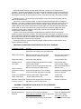
root cause of a problem be diagnosed. One survey revealed the following percentages for A/C
components that required maintenance in a particular fleet. Belts 32%, Compressor/clutch 26% ,
Condenser 12% , Add Refrigerant 12% , Refrigerant Lines/Fittings 11% , Valves 7% . In this
survey electrical problems were not included.
Page 12
Electrical trouble shooting normally starts at the end of a wire, be it a component or a
connector. Check the wiring diagram to find the components that are involved in the malfunction,
start with whatever seems easiest or most likely. Check for continuity through the component(s).
If that doesn't work then check for power or ground, trace which ever leg is not reading correctly.
Example Problem: The clutch slips when engaged, it looks like it has been getting hot and
there is rust dust all over it.
Discussion: A clutch requires at least 12 volts to operate and work best with full voltage of
alternator. The supply voltage should be checked, maybe the coil is internally shorting thus less
inductive load more current draw and thus lowering voltage. Maybe the clutch relay was not
installed and thus the current has to travel the entire length of the wire from the thermostat, this
wire is sized for control circuit and the long length will result in excessive voltage drop when
conducting clutch current. Maybe the clutch relay contacts have corroded which causes
resistance and lowered the voltage.
Solution: All the items mentioned in the discussion are checked, which ever electrical
problem(s) that are found are corrected. The mechanical part of the clutch is cleaned up, the air
gap is checked the engagement surfaces are examined. It may be determined that the clutch is
fine or that a new clutch is also installed, either way the root cause of the problem is found rather
than just replacing the malfunctioning component.
Knowledge of basics, experience and full fledged trouble shooting is what it takes to keep
systems operating correctly.
ABNORMAL COMPRESSOR NOISE WHEN CLUTCH IS NOT ENGAGED.
POSSIBLE CAUSE
Drive belt
ACTION
REMEDY
Check tension and inspect.
Adjust or replace belt.
Strobe light check belt bounce and clearances.
Faulty clutch bearing
Remove drive belt, turn clutch by hand,
Listen and feel for bearing roughness.
Remove clutch bearing or
complete pulley rotor.
Idler pulley bearing
Check idler pulley bearing.
If rough replace idler.
Scrapping sound
from clutch
Inspect for dirt/grit trapped behind front plate.
Check supply voltage
Inspect for correct air gap space all around
Remove and inspect for deep scoring.
Remove and clean
Correct for low voltage.
May be corrected with pry
Replace clutch.
Inspect and torque bolts, if any are loose
check mount holes and welds for damage.
Replace any damaged bolts
Repair as required.
Loose or missing
compressor mounting
bolt(s)
Loose or out of balance Remove and inspect, retighten bolts
engine crank pulley
Check center machined fit
Torque bolts,
Replace pulley.
Alternator, water pump Locate the other engine driven component
air pump, or other
with listening scope or other device.
Replace component.
ABNORMAL COMPRESSOR NOISE WHEN CLUTCH IS ENGAGED.
POSSIBLE CAUSE
A/C Hose Resonating
ACTION
Check for any body or panel contact.
REMEDY
Add padding or clamp.
Excessive discharge
Pressure.
Check for Poor air flow at condenser.
Spray water on condenser, listen for less noise.
Check pressures with gauge set.
Recover/Recharge W/o Non-Condensables.
Clean coil, replace bad fan.
Correct over charge
(See Note on Charge
Determination Work sheet)
Page 13
Compressor clutch.
Inspect clutch. Check field coil, c-clip loose.
Repair to lock coil in place.
Liquid Refrigerant
Entering Compressor.
Check Suction Fitting for Frost or unusually
Cold Fitting with high suction pressure.
Replace TXV, Recharge
with Proper Charge.
Compressor failing.
See Compressor Replacement Procedure.
Add oil and retry or replace.
SERVICE EXPERIENCE TIPS:
In rare but significant cases, oil has transferred out of the compressor and collected in the
condenser and impeded refrigerant flow. Significant because the system performance was way low
and the problem is difficult to diagnose. The symptoms draw a conclusion of bad TXV. However
having changed the valve twice the solution had to be found elsewhere in the system. (I don't
remember who suggested it, and was surprised with the results.) In desperation I suppose, the hot
condenser was sprayed with cold water (with system running). The theory is that rapidly condensing
the refrigerant dislodges the oil accumulation and forces it to circulate returning to the compressor.
In several other similar cases the water quenching did not work. While system was open for
TXV change, the condenser was "back flushed" with nitrogen. Special hoses were made so the exit
hose was directed into a five gallon bucket. The condenser was purged and a "slug" of oil was
splattered all over the inside of the bucket (use lid on bucket). At first the flow seemed restricted, then
as the pressure built up the oil moved and slammed into the bucket relieving the pressure and finally
was free flowing.
Even more rarely the "oil slug" was cleared from the evaporator coil. The oil amount was
estimated and added back to the compressor suction port and the vehicles were never returned for
additional service.
The how, when and why of this oil transfer and collecting are not definable at this time. The
above cases are mentioned as possible solutions when dealing with a problematic system and the
routine solutions have not corrected the performance problem. KNOWING THE TYPICAL
PERFORMANCE OF A SYSTEM CAN BE VERY VALUABLE IN SPOTTING THESE TYPES OF
ANOMALIES.
TROUBLE SHOOTING, EXTENDED FULL SYSTEM GUIDE
Unit Not Air Conditioning Well: POSSIBLE CAUSE
1) Dirty return air filter, evap. air flow blockage, faulty blower motor
2) Air leakage around coil, cover not fit correctly up to seals inside
3) Dirty condenser coil, cond. air flow blockage, faulty fan motor or blade
4) Under charge, Loss of Refrigerant
5) TXV stuck open, eroded valve seat or needle
6)TXV stuck closed, head charge loss, restricted flow (ice, wax, debris)
7) Restricted receiver drier
8) Other system blockage, dented pipe, pinched hose, collapsed liner
9) Slow compressor speed, too small compressor for system
10) Belt slippage, clutch slippage
11) Non-condensable air in system
12) Severe over charged
13) Too much oil in system
14) Faulty compressor
RELATED READINGS
Low Suction Pressure
High Head Pressure
Low Head Pressure
High Suction Pressure
See 1, 4, 6, 8,
13
See 3,
7, 8,
11,12
See 2, 4,5,
8, 10,
14
See
5,
9,10, 12, 14
Page 14
MAINTENANCE EQUIPMENT (Items may be optional depending on level of service.)
Protective Eye Ware, Insulated Gloves, eye wash station, first aid kit all other safety equipment
Torque Wrenches
Schrader Valve Service Tool
[OMEGA P/N 41-91290]
Belt Tension Gauge
[P/N 41-93862
Straight Edge Ruler and Dial Caliper
Dual Thermocouple Digital Thermometer
Manifold Gauge Set with Hoses and End Couplers for R-134a service ports
[P/N 41-89772]
Complete Recovery/Recycle Machine with closed loop flush kit option, Drilled out TXV Block Valve
Vacuum Pump, two stage 7 CFM minimum (capable of. 500 to 25 micron vacuum)[P/N 41-90057]
Vacuum Pump Oil 22 oz service change for above
[P/N 41-90022]
or Vacuum Pump, two stage 5 CFM minimum (capable of 500 to 25 micron vacuum)[P/N 41-90056]
Vacuum Pump Oil 16 oz service change for above
[P/N 41-90016]
Micron Vacuum Gauge
Nitrogen Bottle/Cylinder with Pressure Regulator and Gauges
R-134a Refrigerant Supply Cylinder
Heater Wrap Pad/Blanket for Refrigerant Cylinder Pressure Elevation
Accurate Weight Scale
[P/N 41-15220]
Oil Injector, Capable of adding Oil and Dye to Closed System with Pressure
UV-Dye Additive or Oil with Dye
UV Light Source and Protective Eye Ware
Correct Viscosity Compressor Oil
[See OEM Oil Charge List]
Solvent Flush Kit and Supplies
[P/N 41-91046]
Power Flushing system
[P/N 41-01490]
OZ /ML/CC Graduated Beaker or Cup for measuring oil
Small Container/Dispenser with Mineral Oil (R-12 compressor oil)
Soap and Water Solution Spray Bottle (min), Radiant Leak Detector Solution (better)
Electronic Leak Detector and replacement tips [P/N 41-15202]
DVOM (Digital Volt Ohm Meter) and Ampere Meter (Single wire clamp)
Selection of Electrical End Connectors, Ring Terminals, Star Washers, Etc.
High Grade Electrical Contact Cleaner
Electrical Tape, Tie Wraps
Heavy Duty Anti-Chafe Material "Mill Hose" (Similar to Fire Hose)
Fin Comb
Foaming Coil Fins Cleaner (Omega P/N 41-19990)
Odor Eliminator (CLEAN AIR BRAND P/N 41-00001 2.5 oz Spray can)
(CLEAN AIR BRAND P/N 41-00003 1 gallon with Sprayer/Hose)
REPLACEMENT PARTS see parts brake downs at end of booklet
O-RING SELECTION see parts brake downs at end of booklet
Page 15
MAINTENANCE SERVICE PROCEDURES
NOTE: FOR REFRIGERATION RELATED SERVICE CONTINUE TO THAT SECTION
MAINTENANCE PROCEDURES GENERAL NOTES:
FOLLOW ALL SAFETY AND OPERATIONAL PRECAUTIONS
WARNING: THE UNIT MAY CYCLE ON THE FANS AND COMPRESSOR UNEXPECTEDLY AS
CONTROL REQUIREMENTS DICTATE. BEWARE OF UNANNOUNCED STARTING, REMOVE
POWER PRIOR TO TOUCHING COMPONENTS THAT NORMALLY MOVE.
REFERENCE FOR COMPRESSOR AND MOUNT BOLTS (CHECK QUARTERLY)
TORQUE SPECIFICATIONS - BOLTS INTO ALUMINUM OR CAST IRON THREADS
Note: Max value based on oil in threads and on head bearing surface.(Clean/dry values would be
slightly higher.)
S.A.E. BOLTS
TORQUE IN FOOT-LBS
(GRADE 8 HIGHLY RECOMMENDED FOR ALL ENGINE MOUNTED BOLTS)
Follow any information from mount manufacture if available.
BOLT SIZE- Grade 2 (not for
Grade 5
GRADE 8
Thread Pitch compressor mounting) Aluminum Cast Iron Aluminum Cast Iron
1/4-20 UNC
6
7
9
11
5/16-18 UNC
12
15
18
22
3/8-16 UNC
20
30
34
40
7/16-14UNC
35
45
50
58
7/16-20 UNF
(40)
50
(55)
65
1/2-13 UNC
55
70
70
92
1/2-20 UNF
(60)
75
(95)
110
5/8-11 UNC
110
135
150
190
5/8-18 UNF
(120)
155
(170)
215
METRIC BOLTS
BOLT SIZE
M6 x 1.0
M8 x 1.25
M10 x 1.5
M12 x 1.75
M14 x 2.0
M16 x 2.0
TORQUE IN FOOT-LBS
Grade 8.8
Grade 10.9
Aluminum Cast Iron Aluminum Cast Iron
5
7
8
9
13
18
18
23
22
30
35
45
40
55
60
75
65
85
95
120
110
130
135
175
Grade 12.9
Aluminum Cast Iron
8
9
21
27
40
50
75
95
110
145
165
210
TORQUE SPECIFICATIONS REFRIGERANT FITTINGS (always use longer backup wrench)
O-RING Fitting Torque ft-lb
Fitting
Threads Tubing O.D. FLARE Fitting
Torque ft-lb
Size
/ Hose I.D.
Aluminum
Steel
#4
7/16-20 1/4 / na
10 - 15
5-7
5 - 10
#6
5/8-18 3/8 / 5/16
20 - 25
10 - 13
10 - 15
#8
3/4-16 1/2 / 13/32
35 - 40
15 - 20
15 - 22
#10
7/8-14 5/8 / 1/2
50 - 60
21 - 27
22 - 30
#12
1-1/16-12 3/4 / 5/8
70 - 80
28 - 33
28 - 36
Switches
na
5 - 10
Page 16
5-7
5 - 10
COMPRESSOR DRIVE BELT MAINTENANCE
There are several factors that have major effects on compressor drive belts life expectancy and
reliability. Belt alignment and proper tension are the two most critical and controllable by the
installer and end user. When improperly installed and/or maintained drive belts can cause
significant damage to equipment as well as pose a safety issue. Other factors include belt
clearance, temperature/heat of use and fluids damage.
Alignment includes angular and parallel both should be obtained as close as possible.
Tolerance in mounting holes, welded plates and plate flatness can cause misalignment. When
originally installed the mounting bolts may have been loosed and the pulleys aligned. Later
service work may require the same type of adjusting or shimming. Short run life on a belt might
indicate that a particular vehicle needs alignment checked.
A high quality straight edge and a precise measuring instrument like a dial caliper will be
required to adequately check alignment. Lay the straight edge across the pulley that protrudes the
most, usually the drive pulley on the engine, measure to the edge of the belt and then compare to
relative measurement of second pulley for parallel/offset alignment. Further check top, bottom,
front, and back to check angular alignment. Make any correction required to achieve the best belt
life. Check idlers in the same manner as they too can wear on a belt.
Drive belt tension if to light will promote slippage that will cause heat. Over tension will stress
bearings of driven component as well as early belt failure. All belts require a "run-in period" during
the first 10-12 hours of run time a belt will stretch more then the rest of its service life. It is
important therefore to re-tension per guidelines below.
DRIVE BELT TENSION GUIDELINES
Check the tension when the belt is hot from running. If it is below the threshold value, then
allow it to cool and adjust to re-tension value. If installing a new belt start with that value with belt
cold.
DRIVE
Re-Tension If
Re-Tension
New Belt Initial
Below(Threshold) Run In Belt To Tension Lbs
Compressor
Alternator
A grove
A grove
80
70
105
90
Poly-Rib Belt
6 Ribs
90
110
& Serpentine
or More
Poly-Rib Belt
& Serpentine With Spring Tensioner ----NON ADJUSTABLE
130
110
145
Please follow belt manufacture guidelines regarding gauge selection, operation, calibration and
any specification that may contradict above values.
RETURN AIR FILTER, RELAY BANK and THERMOSTAT SERVICE
SPECIFIC CAUTION: Do not allow oils to drip into or on plastic drain pan or any plastic part of
these systems as material will absorb and become brittle and prone to crack.
Follow maintenance schedule, or clean as required. Series Model EF1, EF2, & EF3 the main
cover must be removed. Model EF3 remove smaller end louvers first. Relay bank is now
accessible. Remove four screws and allow drain pan to hang down (clean as required).
Thermostat is now accessible for service if needed. Rotate filter end catches and slip filter frame
down and out. Use mild soap and water with brush to clean, carefully use shop air to dry, apply
spray filter enhance directly to screen as desired (per manufactures directions). Note if thermostat
probe was pulled out of coil, then reinstall between coil fins right next to original location to reestablish full contact. Carefully reinstall all components.
Page 17
ODOR, CAUSE AND REMOVAL (This is a service matter, not a warranty issue.)
Odor is caused by naturally occurring bacteria growing in any water remaining in the
evaporator housing, drain pan, drain hoses and perhaps on coil. Because of the low temperature
of the air, limited discharge flow (that might otherwise flush growth away) and in the absence of
sunlight an ideal situation for the growth of bacteria and fungi is unavoidable created. To remove
the odor, remove the microbiology. By properly cleaning components of dirt formed from dust that
holds water the colony will not have it's first foothold. Washing with white vinegar is probably the
most effective method of removing the contaminants. A popular effective option between
complete cleanings is to routinely use a spray A/C deodorizer that will freshen by chemically
neutralizing nature's little troopers. (Also see operation procedures to run blowers only to dry unit.)
BLOWER MOTOR ASSEMBLY and SPEED RESISTOR(S) REPLACEMENT
Disconnect battery ground cable.
Follow same procedure as return air filter service. Disconnect wiring, remove failed component,
install replacement. Check operation especial correct direction of rotation of blower motor.
(Permanent magnet D.C. motors will reverse if positive and negative wires are exchanged, air
delivery will be low.)
CONDENSER FAN ASSEMBLY(s)
Disconnect battery ground cable.
If one fan motor has worn out to the point of failure, please consider replacing them both so as to
avoid other damage due to high pressure in the near future. Check operation, especial correct
direction of rotation of fan motor. (Permanent magnet D.C. motors will reverse if positive and
negative wires are exchanged, do not rely on wire colors alone.)
REFRIGERATION SERVICE PROCEDURES
FOLLOW ALL SAFETY AND OPERATIONAL PRECAUTIONS
WARNING: THE UNIT MAY CYCLE ON THE FANS AND COMPRESSOR UNEXPECTEDLY AS
CONTROL REQUIREMENTS DICTATE. BEWARE OF UNANNOUNCED STARTING, REMOVE
POWER PRIOR TO TOUCHING COMPONENTS THAT NORMALLY MOVE.
WARNING: NEVER USE SHOP AIR FOR LEAK TESTING. IT HAS BEEN DETERMINED THAT
PRESSURIZED REFRIGERANT AND AIR RICH MIXTURES CAN BE COMBUSTIBLE WHEN
EXPOSED TO AN IGNITION SOURCE.
ALWAYS USE MINERAL OIL TO LUBRICATE O-RINGS AND FITTING THREADS. PAG OIL IN
THE SYSTEM WILL ABSORB MOISTURE AND BECOME VERY ACIDIC AND CORROSIVE, DO
NOT USE IT ON EXTERNAL PARTS.
USING ONLY THE COMPOUND GAUGE OF THE SERVICE SET FOR DETERMINATION OF
VACUUM LEVEL IS NOT RECOMMENDED BECAUSE OF ITS INHERENT INACCURACY.
VACUUM PUMPS REQUIRE ROUTINE OIL CHANGE TO MAINTAIN FULL PUMP DOWN
CAPABILITIES. A TWO STAGE VACUUM PUMP IS REQUIRED TO ACHIEVE VACUUM IN THE
1000 MICRON AND BELOW RANGE.
WEA R EY E P R OTEC TI O N A ND G L OVES AN Y TIME RE FRI GE RAN T HA ND LI NG IS
INV OL VE D!
Page 18
PLEASE READ ALL SECTIONS THAT FOLLOW FOR TIPS AND INSIGHT, THIS MANUAL IS
NOT A FULL SUBSTITUTE FOR INITIAL TRAINING IN A/C SYSTEM DIAGNOSIS OR
REFRIGERANT HANDLING.
PREPARING MANIFOLD GAUGE SET FOR USE
If the manifold gauge set is new or was open to atmosphere then it will require evacuation to
remove air to avoid contamination of system. Close both high and low side end couplings. Open
both the high side and low side manifold valves. Connect the gauge set to the vacuum pump and
fully evacuate. Assuming the gauge set will next be connected to a charged system for service or
annual maintenance check, then next connect the service line with self sealing end fitting to
refrigerant supply cylinder. Slowly open cylinder valve to allow vapor only into the gauge set until
the low side pressure is 40 to 60 psi, close cylinder valve. Close both manifold valves and the set
is now ready to connect to a charged system.
With a four hose manifold set the procedure is nearly the same except the cylinder and vacuum
pump will both be connected and all hoses will be evacuated, close the valve to the vacuum pump
and then refrigerant vapor charge the other three hoses.
MANIFOLD GAUGE SET USAGE
The manifold set is used to connect to system and thus determine system operating pressures,
add refrigerant, evacuate and in rare cases equalize high and low side pressures. The standard
three hose version requires extra care in exchanging yellow (service) hose from cylinder to
recovery machine to vacuum pump. The more convenient four hose version has the advantage of
allowing two service items to be connected at he same time. Usually the cylinder remains
connected and the recovery machine or vacuum pump are not used at the same time. When it is
time to exchange them the hose connection will have only a vacuum (or very little pressure).
With the system OFF connect the service couplings to the service ports. With all manifold
valves closed, rotate the end coupling valve red knob to move the plunger forward to open the
service port schrader valve. The high side pressure gauge will now indicate system pressure. It
will dependent on the average ambient temperature of the system (not on the quantity of liquid in
the system even if the system is low of charge just as long as there is some present to produce
enough vapor present). Next open the low side end coupling valve, the low side pressure gauge
should read the same as the high side (system has been off long enough to equalize). Too verify
open both manifold valves, check pressures again. Any difference is GAUGE ERROR and should
be noted, usually as correction to wider scale high side gauge. Closes manifold valves before
proceeding.
With manifold gauges attached the system may now be run for annual pressure reading check,
see the system performance chart for procedure.
If some service is determined to be required then proceed with full diagnosis of system prior to
adjusting charge of refrigerant. First see "leak check" and then "adjusting the charge" below.
After testing is complete, to prevent trapping liquid refrigerant in the manifold/hose set and
robbing charge from system, entire set must be brought to suction operating pressure. First close
the high side end coupling (red knob fully counterclockwise). Next slowly open both manifold
valves, allow both gauges to equalize at suction pressure. Close the low side end coupling (blue
knob fully counterclockwise), close both manifold valves. Remove the low side coupling with
system still running, however high side will be hot and at high pressure at service port so it is best
to wait until system is turned off and cooled down before removing the high side end coupling.
REFRIGERANT LEAK CHECK - SYSTEM WITH PRESSURE
If pressure reading were diagnosed to require adjustment, then most likely it was determined
that some loss of refrigerant has occurred. So depending on the amount that needs to be added,
how severe is the problem? Was it a very small amount that could be called normal permeation or
a larger amount indicative that a repair is required? In either case the correct thing to do is to
carefully go over the system and fix any leak that can be identified! It is only going to get worse.
Fix any leak that can be identified.
Page 19
1)
OMEGA highly recommends UV dye in all A/C systems. Use UV protective/enhancement
eye ware, and thoroughly examine entire system with UV light.
2)
Soap and/or radiant dye solutions may be sprayed, brushed or poured on specific
locations like end fittings. In certain cases like a large leak, electronic leak detectors will not
function correctly and thus solution testing may be necessary.
3)
Electronic leak detectors are often convenient for checking the general area of a coil as
well as end fittings. Proper usage requires slow and deliberate motion. Refrigerants are heavier
than air and will tend to collect in the bottom of the drain pan if not disturbed by surrounding air
movement. Follow instructions provide by equipment manufacture.
If no leaks can be found and the system was diagnosed to need adjustment and if the amount
finally added is less than half a pound then dye should be added and the unit should be rechecked
in the next quarterly. If a pound or more is added later (see Charge Determination), then dye
should be added and the system should be leak check again after thirty minutes to one hour of run
time.
REFRIGERANT LEAK CHECK - SYSTEM WITHOUT PRESSURE
If the system had dye then the UV light method is straight forward. A system without dye
should also be entirely looked over first with a bright light. If any thing obvious or highly suspicious
is found then repair it prior further pressure testing.
If nothing is visually obvious, then next step of the preferred method, is to charge the system
with only enough refrigerant vapor to attempt build up to 30 / 40 psi and then add nitrogen to raise
pressure to 150 / 200 psi. There will be enough refrigerant for electronic leak detector to work and
enough pressure for solution bubbles to form. Do not operate system!
Remove the test gas, locate and fix leak(s), replace filter drier, evacuate/dehydrate unit.
EVACUATION / DEHYDRATION (Double Nitrogen Flush and One Time Deep Vacuum)
Note: Pag oil is very hydroscopic (absorbs water) DO NOT use oil from previously open
containers.
Both Polyalkylene Glycol (PAG) and Poly Ester (POE) oil will pull moisture right out of the air.
Moisture causes a chemical reaction which creates ACID. Evacuation will not remove the
moisture and will not reverse the chemical process.
Moisture is always present in atmospheric air. The presence of moisture in a refrigeration
system will have undesirable effects. Freezing up at metering devices, acid and acid sludge
formation and resulting in metal corrosion shorten the service life of an improperly serviced unit. A
double dry nitrogen flush evacuation should be performed after any catastrophic loss of refrigerant
or any major component is replaced (evaporator, condenser, or compressor). By following good
procedure (capping lines) and/or limiting exposure time, a single evacuation will normally suffice
for minor service like o-ring leak repair. Regardless a new receiver drier should be installed any
time system is breached.
Keep the system ambient temperature above sixty degrees Fahrenheit to speed the
evaporation of any moisture. At lower temperatures ice may form before moisture removal is
complete. Remember also that the system will cool down as result of lowering the internal
pressure. Off season service should be performed in heated shop, alternate heat source such as
heat lamps will also help. At least plan to perform evacuation during the warmest part of the day.
(To get really technical see the note below.)
For repair service, first having recovered any refrigerant, have vacuum pump service hooked
up and ready to evacuate as soon as work is complete. Make the drier replacement the last
activity and immediately start vacuum pump.
Normally evacuate from both sides (manifold valves both open). Open valves slowly to prevent
large inrush of air purging oil out of pump vent. By hand, turn compressor over several times once
full vacuum is achieved.
Page 20
For double nitrogen flush, close low side manifold valve when adding nitrogen through
high side. Close high side manifold valve, connect vacuum pump and evacuate by opening low
side valve. By hand, turn compressor over several times once full vacuum is achieved. After full
evacuation (depending on vacuum pump, 10 to 30 minutes), close low side manifold valve and
stop vacuum pump and assure system holds vacuum for a minimum of five minutes. (some
pressure rise may be observed on a micron gauge; say about 500 microns, but this would be
completely unperceivable on a compound gauge). If system does not hold vacuum, then diagnose
leak with preferred method above (partial refrigerant). Upon successful vacuum hold test, repeat
dry nitrogen purge through high side procedure again, only this time loosen low side hose at
manifold and allow nitrogen to flow through system to flush out any moisture that vaporized (boiled
off) during vacuum hold test. Final evacuation to dehydrate the system should be to below 1000
microns.
Alternatively a single, double, or triple refrigerant flush will work similarly except recover
the "flush through refrigerant" for proper recycling. If the system has been open or empty for a long
time, then evacuation times should be extended and triple flush with full evacuations between is
required. Single flush/evacuation (30min) is 90% efficient, Double 97%, Triple flush/evacuation
99% effective moisture removal.
One time deep vacuum is for new systems (not previously charged) and minor short
duration breach repaired systems. By hand, turn compressor over several times once full vacuum
is achieved.
After full evacuation (depending on vacuum pump, 15 to 30 minutes), close low side manifold
valve and stop vacuum pump and assure system holds vacuum for a minimum of five minutes.
(some pressure rise may be observed on a micron gauge; say about 500 microns, but this would
be completely unperceivable on a compound gauge). If system does not hold vacuum, then
diagnose leak with preferred method above (partial refrigerant). Upon successful vacuum hold
test, restart pump for another 10 to 20 minutes. Final evacuation of the system should be
performed at above 60 degrees temperature.
Note: VACUUM TO WATER VAPORIZATION TEMPERATURE
Compound gauge readings (inches of Hg is read as inches of mercury vacuum)
0
@28.92 inches of Hg [96.6% vacuum] =25,400 microns; boiling point of water is 79 F
0
@29.13 inches of Hg [97.4% vacuum] =20,000 microns; boiling point of water is 72 F
0
@29.80 inches of Hg [99.4% vacuum] = 4,500 microns; boiling point of water is 32 F
@29.88 inches of Hg [99.86%]
= 1,000 microns = 1 mm of Hg Absolute Pressure
RECOVERY NOTES
Prior to recover drain oil from collection container that may have settled since last use, note this
amount. Learn the characteristics of your machine. If it retains oil, then consider adding the value
to the amount collected. After recovery record amount collected for add back calculations.
The machine may cycle off and then back on in about five minutes or more. In fact as
refrigerant continues to come out of solution from the PAG oil in the system it will raise pressure.
This slow process may be observed when a component is removed, capped and checked for
pressure later. It sure makes a mess when the bubbling oil comes out of an evaporator or
condenser that has been rapidly removed and set aside.
A complete recovery could take numerous hours. If time were not an issue or if a person could
plan the work schedule, then recovery should be done during lunch or even better yet at the end of
the day and then start machine again in the morning.
Recover refrigerant per machine manufactures instructions and stay informed with current
industry journals for any legislation changes.
ADDING REFRIGERANT FULL CHARGE (RECOVERED AND EVACUATED SYSTEM)
Note: If using a charging station, routinely calibrate it per manufactures instructions.
Page 21
Set up and pre heating of the supply cylinder is assumed to have taken place during
evacuation. Place R-134a supply cylinder on weight scale that was set at zero and correct units
are displayed. (Lbs or Kg). Take note that an empty 30lbs cylinder weights about 5 1/3 lbs, and
the heater belt should also be on the cylinder, so be prepared with enough refrigerant to compete
the charge based on engraved plate attached to vehicle by installer. After final evacuation close
both/all manifold valves. Check that the cylinder valve is open and positioned correctly to dispense
liquid. Depending on condition and type of gauge/hose set, supply hose should be filled up to
manifold valve, if the hose was empty then the scale will show how much refrigerant was required
to fill it. Re-zero the scale.
With the a/c system off, charge with liquid refrigerant into the high side only. The heated
cylinder will cool slightly as its elevated pressure forces fluid into a/c system. Shut off manifold
valve when scale indicates the full charge. (Using this method eliminates the possibility of noncondensable gas entering the system coming from the top vapor of a recovered/recycled cylinder.)
Start engine, warm up, and engage clutch. Perform and operational test deemed appropriate.
See next section on charge determination.
When ready to disconnect, to prevent trapping liquid refrigerant in the manifold/hose set and
robbing charge from system, entire set must be brought to suction operating pressure. First close
the high side end coupling (red knob fully counterclockwise). Next slowly open both manifold
valves, allow both gauges to equalize at suction pressure. Close the low side end coupling (blue
knob fully counterclockwise), close both manifold valves. Remove the low side coupling with
system still running, however high side will be hot and at high pressure at service port so it is best
to wait until system is turned off and cooled down before removing the high side end coupling.
OPTIMUM CHARGE DETERMINATION
The main goal is to provide maximum cooling and can be measured directly as temperature
drop across the evaporator (Delta-T). With R-12 the procedure was easy, clear the sight glass
and add a little to get sub-cooled liquid supply to the expansion valve. Now with R-134a this
approach must be modified as the high side pressure can exceed optimum for system maximum
flow rate. So the sight glass is now used mainly for moisture eye reference.
A system that is otherwise sound but is low on refrigerant will produce a better Delta-T as
refrigerant is added (system must stabilize between incremental additions). Recording all
temperature readings and both high and low pressures will help to see the trend. Notice that
single point thermocouples have a difficult time in moving air streams, recording high to low swings
is required. The method also requires near maximum heat load conditions for best results. It
should be performed with windows open to reduce re-circulation air effects and to attempt to have
steady state inlet air temperature and humidity.
Another charging method is to measure the ambient air temperature at the condenser inlet,
enter the temperature/pressure chart, read the corresponding pressure value and adjust system
charge to obtain same high side gauge reading. This procedure does not assure maximum
cooling performance.
Omega recommends a combination of the two methods. The engine should be running at
about 3/4 of max road speed RPM. Incrementally add charge to obtain the best evaporator
performance. Have the pressure value on hand and consider it as the maximum except if the
delta-T performance is still getting significantly better. As an example: two degrees better delta-T
for a 5 to 10 psi rise above the chart value. If the system were way undercharged to start, you will
see that the delta-T at first gets rapidly better with each add, but then improves only slightly as
correct charge is approached. At the same time the high side pressures don't change much at
first, but began to increase in larger steps.
When the initial charge is about right and little delta-T change is observed with first add and
high side is close to chart value, then the system is ready. If the high side jumps up and is now 30
to 40 psi above the chart value then even if the evaporator performance got slightly better then for
sure it's time to stop adding refrigerant, shut off system and recover last increment added.
The proceeding is for system service when exact amount of refrigerant in system is not known.
If the system were being fully recharged after service then the data plate riveted under the hood
Page 22
should be stamped with charge weight. In this case charge to that amount and verify high side
value from chart. Typical charge weight will be about 5.2 lbs for EF1, 2, or 3 Evaporator with
CS1 systems and 6.5 lbs is typical for systems with CS6 and second (slave) unit.
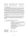
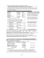
(OPTIMUM) CHARGE DETERMINATION WORKSHEET R134a
CAUTION: DO NOT CONTINUE TO OPERATE SYSTEM WITH LOW SIDE PRESSURE LESS
THAN 10 PSI, begin with enough refrigerant to prevent compressor damage.
Compressor/Engine RPM at 3/4 max road speed RPM. Evaporator main cover on and louvers all
open. Open windows for max heat load and attempt to maintain steady state entering air
temperatures. Check/calibrate gauges (see manifold gauge set usage) and thermocouples
comparative readings, note any Correction Factor difference to be added or subtracted. It is normal
(especially during light load operation) for the "TXV to hunt" for setting, thus suction pressures often
range or swing. This can also produce swings in high side pressures. Record ranges or swings in
readings. NOTE: If system is operated 30 deg above charge temp, then recheck & readjust charge.
Example: If charged at 70 deg to 130psi then at 100 deg expect 250psi. Whenever possible, charge
at hottest condition close to max expected during operation and obtain best overall performance.
(
. lbs)
Amb
Added 0.2
Guide
Added 0.2
Max
Added 0.2
Added 0.2
Start or
Temp Line
High
(If known
Into
(If known
Desired
(If known
Press. Unknown
(If known
See
Record
Cond. High
Total now
Total now
Total now
Total now
Delta-T
. lbs)
deg F Pressure Note
. lbs)
. lbs)
. lbs)
Above High/Low
Pressures
DT & H/L
DT & H/L
DT & H/L
DT & H/L
PLEASE MAKE COPY OF THIS FORM, FILL IN ALL INFORMATION & ADD TO MAINTENANCE FILE.
62
64
66
68
70
72
74
76
78
80
82
84
86
88
90
92
94
96
98
100
102
104
110
115
120
125
130
135/150
140/155
145/160
150/165
155/170
160/175
165/180
170/185
175/190
180/195
185/200
190/205
195/210
200/215
205/220
210/225
215/230
106
109
112
115
118
120
124
128
220/235
230/245
240/255
250
265
275
290
305
210
250
300
360
Page 23
132
320
360
440
High pressure switch cut out range 28 kg/cm3+/-10% = 400psig+/-40
ADJUSTING REFRIGERANT CHARGE
Note: If using a charging station, routinely calibrate it per manufactures instructions.
Overcharging is to be avoided if at all possible. If it has occurred it is likely on a system that is
now operating in a much hotter ambient then when the system was initially charged. It is also
possible that a mistake was made or equipment malfunctioned (not calibrated is really an operator
problem not a malfunction of the equipment per say). Many charging stations use a strain gage
weight scale that requires calibration any time they are moved, especially if a nearly full cylinder is
sitting on the weight platform. A bump or jolt from rolling over a floor seam or electric cord is often
enough to affect the machine calibration.
Following all proper steps covered in previous sections. Adjusting charge is simply either
adding or removing refrigerant from system utilizing gauge set.
Adding is normally done with system running and will typically be adding charge to obtain best
evaporator performance while keeping head pressure in acceptable range. Refrigerant vapor is
added through low side. You may turn the supply cylinder over (valve up for vapor) or more
simply, slowly open low side manifold valve, do not allow suction pressure to rise too rapidly and
no more than 40 to 50 psi. Adding refrigerant gradually prevents the possibility of "liquid slugging
damage" to compressor. Allow sufficient time for the system to stabilize after each adjustment.
Normally five to ten minutes is sufficient for each two tenth (0.2 Lbs=3.2 oz) added incrementally.
Check and record performance in chart form for each add to keep track and confirm final total.
Any time the cause is not known for head pressure in an elevated range, then the system
should be thoroughly checked for any other problem. In this rare case that charge needs adjusting
down, then the system is turned off for vapor recover following machine instructions. It would be
possible to weigh the recovery tank and observe the amount transferred. The alternative is to
perform short intervals of recovery with system on performance checks each time.
COMPRESSOR REPLACEMENT
Normally a compressor is not to be replaced unless it is not pumping the suction side down or
is locked up. Do not mistakenly replace a compressor when in fact the system is over or under
charged. The high side pressure may not raise if the system has a flow blockage or restriction. A
lack of flow will prevent the working fluid (refrigerant) energy transfer that results in high side
pressure.
THERE IS ONE FAULT THAT MAY BE MISDIAGNOSED AS A BAD COMPRESSOR, AND
THAT IS IF THE EXPANSION VALVE IS STUCK OPEN OR PARTIALLY OPEN! IN THIS
EVENT, THE SUCTION PRESSURE WILL BE HIGHER THAN NORMAL AND THE HEAD
PRESSURE WILL BE BELOW NORMAL. See the following section REPLACING TXV Block
Valve - Defective valve diagnosis.
Two other indicators of poor compressor performance include rapid pressure equalization when
turned off and an inability to pull a vacuum if the suction hose were pinched off (this old procedure
is not recommended as liner of hose may be damaged).
Compressors may be one of four basic types, regardless they are all designed as vapor
pumps. As such it should transfer enough refrigerant to lower suction pressure to below 40 psi
when properly sized to system and turned at road speed RPM.
Page 24
A noisy compressor that still pumps “well”, may just need a oil level service or removal oil
level check. (See trouble shooting for other possible noise related problems.) Use an oil injector
to slowly add several oz of oil into suction port, up to 50% of OEM charge for compressor model.
If “removal checked” and the compressor is oil "dry" but clean, add recovered amount plus 50% of
OEM charge back into suction port and follow all appropriate procedures to recharge.
If the compressor is inoperative and the system still has refrigerant pressure, recover the
refrigerant with approved machine. Record amount of oil collected.
Remove compressor and drain oil into measuring cup. Examine oil, if the compressor broke
and locked up right away, then oil will likely appear mostly clean and perhaps with some small
metal particles. In this case a nitrogen back flush of condenser and hose from compressor is still
recommended. The receiver drier should have collected any other debris.
If however the oil appears black or dirty, then all the system components should be individually
nitrogen "back flushed" (reverse direction to regular flow) first. (Solvent flush may also be used to
back flush and will often dislodge particles oil stuck in the condenser, then the trick is to fully
remove the solvent with nitrogen. Carefully follow instructions provided with these types of
products.) The only proper way to final flush the system is to use refrigerant in a closed loop
system. Closed loop flushing kits are available, and some recovery/recycle machines have "flush
kit" options.
If the system was judged to be acceptably clean, then drain new compressor and add back the
amount drained from old compressor or 50% of OEM oil charge whichever is greater plus amount
collected in recovery machine.
If system was flushed and the receiver drier is the only other component being replaced, then
check OEM charge amount and add oil to compressor to achieve total amount listed on data plate.
Oil is to be poured into compressor suction port.
Remove both caps from ports of compressor, verify that compressor is indeed "pre-oil
charged", rebuilt compressors are often shipped dry. Add correct amount of oil. By hand turn the
compressor clutch drive plate at least ten times to distribute oil inside compressor. and assure that
it is not overfilled. Install new o-ring and reconnect suction fitting. Again turn compressor by hand
to assure oil distribution. Remove and replace receiver drier replacing all o-rings (lubricated with
mineral oil). Evacuate and recharge per proceeding sections.
ADDING OIL WHEN COMPONENT IS REPLACED. (when reusing same compressor)
THIS IS PERHAPS THE MOST DIFFICULT DECISION FACED BY THE SERVICE TECHNICIAN
Research has proven that too much oil in a system will degrade the performance, but a system
without enough oil will likely have a premature compressor failure.
The first thing that makes sense is that any time a major component is replaced then oil should
be added to make up for the loss. Consider refrigerant as a major component.
During recovery/removal of R-134a from the system, oil in mixture is also removed. Refer to
specific machine instructions regarding oil collection. It is often noticed that the oil collected and
then drained from machine foams up as the refrigerant in solution is exposed to less pressure.
Allowing time for correct and accurate measurement of oil removed is vital. Complete drainage of
machine collecting system may require repeated attempts. Some machines have an internal
recycle mode that may need to be performed to completely separate the oil from the recovered
refrigerant.
Adding back new oil to replace that amount of oil collected in the recovery process initially
seams quite obvious. Normally with a system whose known service history is simple and for
routine service, like TXV replacement or leaking o-ring replacement, that is the best assumption.
For condenser, evaporator, and hose replacement, determining or estimating the correct
amount of oil to be added back for these components could follow these guidelines;
1) Check the data plate for total amount listed for the system. (Bus system is typically 5 to 8 oz more
than the compressor OEM charge.) Fill in blank at right with amount.
_____
2) Subtract the amount recovery collected.
-_____
Page 25
3) Remove the compressor and drain it, Again subtract this amount.
-_____
THIS REMAINDER REPRESENTS THE MISSING OIL THAT IS DISTRIBUTED
=~T____
THOUGH OUT THE SYSTEM IN FILM FORM ON INTERIOR SURFACES.
4) Add up the total internal volume, the Figure out the percentage of internal wetted volume that
the replaced component contributed to the total wetted volume and add the drier percentage
as it will also be replaced.
Work Sheet: Percentage of internal wetted volume for replaced components.
Model CS1
Condenser
#11.2 =____
[Fill in blank with # for each item used
Model CS2
Condenser
#22.3 =____
in the actual system. Use filled in #s for
Model CS3
Condenser
#15.5 =____
vertical Addition to get #Total at bottom.]
Model CS4
Condenser
#12.3 =____
If condenser is being replaced, then
Model CS5
Condenser
#15.5 =____
after Total is added, get @DecimalModel CS6
#14.0=_____ (Percent) for Cond.# / #Total=@ .___
Model EF1, EF2, EF3
Evaporator
#14.3 =____
Model EF4
Evaporator
#10.0 =____
If Evap is being replaced, then
nd
=____
after Total is added, get @Decimal
2 Evaporator (add to total volume)
Evap. # Divided by #Total =@ .___
nd
=____
2 Evap: Extra hose for liquid, use info below)
nd
2 Evap: Extra hose for suction, use info below)
=____
Hose for liquid (Cond to Receiver-Drier & TXV)
After Total is added, get Decimal
#6 Hose 13/32"
0.104 x length ____ft =#____ for any hose that is replaced
or #8 Hose 1/2"
0.131 x length ____ft =#____
hfl# divided by #Total =@ .___
Hose for discharge (Comp to Cond)
#8 Hose 1/2"
0.131 x length ____ft =#____
hfd# divided by #Total =@ .___
or #10 Hose 5/8"
0.163 x length ____ft =#____
Hose for Suction (Evap to Comp)
hfs# divided by #Total =@ .___
#10 Hose 5/8"
0.163 x length ____ft =#____
or #12 Hose 7/8"
0.229 x length ____ft =#____
Receiver Drier
2.6
=+2.6
R/D #(2.6)/ #Total=(@ .___)
Add # for each component that is in the system for #Total____ [Add all vertically from above]
4-)cont. Figure out the Decimal for any component(s) being replaced ADD to the Decimal for the
receiver drier (as it will always be changed).@ .___+@ .____+@ .____+(@ .____) = ^Total .____
5-)Multiply step 4)^Total by step 3)~Total for final amount oil missing. ^T____x ~T____oz=____oz
6-)Add step 5) amount to 2) recovered amount plus 3)amount drained from compressor.
5) ____ oz + 2) ______ oz + 3) ______ oz = ______oz { -________=_______}
Final Answer Total 6) This is the system total calculated amount of new oil required.
{ If also replacing compressor, Note that a new compressor has oil in it and thus, subtract OEM
charge from the total calculated and this is the final add amount.}
As you can clearly see, this could really be a complicated situation and would require close
attention to all the math in the above calculations. So the simplified recommendation for
typical bus installation is to add back all the recovered oil plus amount(s) listed below for
each component that is being replaced.
Hose(s) #6 0.05oz per ft, #8 0.063oz/ft, #10 0.078oz/ft, #12 0.11oz/ft _____________
Model EF1, EF2, EF3
Evaporator coil 1.5 oz/45cc
_____________
Model EF4 Evaporator coil
1.1 oz/33cc
_____________
Model CS1 Condenser
2.0 oz/60cc
_____________
Model CS2 Condenser
3.5 oz/100cc
_____________
Model CS3, & CS5 Condenser
2.5 oz/75cc
_____________
Model CS4, & CS6 Condenser
1.75 oz/50cc
_____________
Receiver Drier
0.5 oz/15cc
+ 0.5 oz / 15 cc
Recovered amount
+_____________
TOTAL
=_____________
Total amount to be poured into compressor suction port, not the component!
Disconnect the suction fitting at the compressor, add calculated amount of oil back to
system, by hand turn the compressor clutch drive plate at least ten times to distribute oil inside
Page 26
compressor. and assure that it is not overfilled. Install new o-ring and reconnect suction fitting.
Again turn compressor by hand to assure oil distribution. Remove and replace receiver drier
replacing all o-rings (lubricated with mineral oil). Evacuate and recharge per proceeding sections.
COMPRESSOR OEM OIL AMOUNTS LIST
Model
A-6
SD 510
SD 709
SD 7H15
TM 16HD
TM 21HX
TM26 (NLA)
TM 31HD
UP/UX170
UP/UX200
UX 260
UX 310
BRAND/OIL TYPE (Viscosity)
DELCO 15-118/PAG (150)
SANDEN SP 20/PAG (100)
SANDEN SP 20/PAG (100)
SANDEN SP 20/PAG (100)
1L PAG-ZXL 100/PAG (46)
1L PAG-ZXL 100/PAG (46)
1L PAG-ZXL 100/PAG (46)
1L PAG-ZXL 100/PAG (46)
UNIDAP 7/PAG (46)
UNIDAP 7/PAG (46)
UNIDAP 7/PAG (46)
UNIDAP 7/PAG (46)
OEM AMOUNT
295cc / 10oz
150cc / 5.1oz
150cc / 5.1oz
135cc / 4.56oz
150cc / 5.1oz
180cc / 6.1oz
500cc / 16.9oz
500cc / 16.9oz
160cc / 5.4oz
180cc / 6.1oz
500cc / 16.9oz
600cc / 20.3oz
Note: PAG oil is very hydroscopic (absorbs water), DO NOT use oil from previously open containers. Both
Polyalkylene Glycol (PAG) and Poly Ester (POE) oil will pull moisture right out of the air. Moisture causes a chemical
reaction which creates ACID. Evacuation will not remove the moisture and will not reverse the chemical process. KEEP
COMPRESSOR CAPPED UNTIL READY TO CONNECT TO LINES AND INSTALL NEW RECEIVER DRIER, BEGIN
EVACUATION ASAP.
REPLACING RECEIVER DRIER
The receiver drier (w/filter) is located at the condenser. Recover refrigerant following procedure
above. Have new component and o-rings at hand to limit open system exposure time. Carefully
loosen fitting connections. Remove and replace receiver drier replacing all o-rings (lubricated with
mineral oil). Receiver Drier Add .5 oz of correct oil plus recovered amount.
REPLACING HIGH PRESSURE SWITCH
This component may be on a fitting at the condenser or "spliced in" on the liquid supply hose
after the condenser before the TXV. With system still pressurized, check for continuity. The switch
is depressing a schrader valve and may be replaced with out dropping the refrigerant charge. The
switch may be checked with a special setup of a schrader valve to the nitrogen regulator. Spec.
for P/N 29-30123 Dual Switch: Open until approximately 28psi, closed until 400psi +/-40psi.
REPLACING TXV (Thermostatic Expansion Valve)
SPECIFIC CAUTION: Do not allow oils to drip into or on plastic drain pan or any plastic
part of these systems as material will absorb it and become brittle and prone to crack.
The block valve is located at the evaporator coil. Unit cover must be removed and valve should
be diagnosed as needing replacement before proceeding. Defective valve diagnosis: First make
a temporary blower "close off" out of cardboard to draw air through evaporator coil and tape in
place. Operate system on low blower and hand warm the (bare) disc head of the valve while
observing (may require an assistant) the gauge set. The suction pressure should raise as the
valve opens up, discontinue warming immediately to prevent liquid slugging the compressor. Next
operate the system on high and cool the (bare) disc head (cooling the head may be accomplished
by spraying the head with nitrogen, evaporator deodorizer aerosol or applying ice) observing the
gauge set. The suction pressure should drop as the valve closes, discontinue head cooling
immediately to prevent system from operating below ten psi as this will starve the compressor of
return oil and possible overheat with out the refrigerant vapor cooling effect. If the valve
responded then perhaps it is not the problem after all. Having exercised the valve, observe system
operation after system has stabilized. If the valve did not respond then it should be replaced.
Recover refrigerant. Have new component and o-rings at hand to limit open system exposure
Page 27
time. Carefully loosen all fitting connections. Remove and replace valve replacing all o-rings
(lubricated with mineral oil). Reproduce any insulation that was on original valve and fittings.
END
Page 28
Page 29
Page 30
OLDER UNITS (Included for Service Reference)
Page 31
OLDER UNITS (included for service reference)
Page 32
BY MODEL - ILLUSTRATED PARTS LIST
Page 33
MODEL EF1 EVAPORATOR, ONE DUAL BLOWER
ITEM
P/N
1A
1B
1C
1D
2
3
3 (opt)
3 (opt)
4A
27-19503
40-32429
40-32423
40-32436
40-42910*
31-30902
(31-30927)**
(31-30957)**
40-40123*
6
7
40-32502
28-41400
8
9
10
11
12
13
40-41520
28-94107
28-41520
40-43053
26-19912
40-42840-A
DESCRIPTION
EVAPORATOR COIL
VOLARA TAPE 1/8 X 2
FOAM TAPE 1/2 X 3/4
TAPE VOLARA 1/8 X 1/2
TOP TRAY FOR BUS UNIT
EXP VALVE, BLOCK 2-1/2 TON (EF2 or EF3 single)
EXP VLV, BLOCK 2 TON (EF1 single, EF2 or EF3 tee in)
EXP VLV, BLOCK 1-1/2 TON (EF1 tee in)
BRACKET, RELAY MOUNTING
-Electrical Components Are On Wiring DiagramAIR FILTER ASSY
DRAIN PAN ASSY (W/BRKTS, FOAM COVER &
PORTS)
FRESH AIR RETURN GRILL METAL
EURO LOUVER 3.82" X 10.11"
SHROUD, MAIN COVER 3 LOUVER
BRACKET, BLOWER SUPPORT
BLOWER, DUAL SCROLL 12V (Complete Assy)
WALL FOR SINGLE MOUNT MOTOR
*4/19/05 ** 10/10/07
Page 34
QTY.
1
6.85 FT
1.5 FT
1.2 FT
1
1
1
1
1
1
3
1
1
1
1
Page 35
MODEL EF2 EVAPORATOR, TWO DUAL BLWRS
ITEM
P/N
1A
1B
1C
1D
2
3
3 (opt)
3(opt)
4
27-19503
40-32429
40-32423
40-32436
40-42910*
31-30902
(31-30927)**
(31-30957)**
40-40123*
6
7
8
9
10
11
12
13
40-32502
28-41400
40-41520
28-94107
28-41520
40-43053
26-19912
40-42911*
DESCRIPTION
QTY.
EVAPORATOR COIL
VOLARA TAPE 1/8 X 2
FOAM TAPE 1/2 X 3/4
TAPE VOLARA 1/8 X 1/2
TOP TRAY FOR BUS UNIT
EXP VALVE, BLOCK 2-1/2 TON
EXP VLV, BLOCK 2 TON (EF1 single, EF2 or EF3 tee in)
EXP VLV. BLOCK 1-1/2 TON (EF1 tee in)
BRACKET, RELAY MOUNTING
-Electrical Components Are On Wiring DiagramAIR FILTER ASSY
ASSY, DRAIN PAN W/BRKTS, FOAM COVER & PORTS
FRESH AIR RETURN GRILL METAL
EURO LOUVER 3.82" X 10.11"
SHROUD, MAIN COVER 3 LOUVER
BRACKET, BLOWER SUPPORT
BLOWER, DUAL SCROLL 12V (Complete Assy)
WALL DUAL BLOWER MOUNTING
*4/19/05 ** 10/10/07
Page 36
1
6.85 FT
1.5 FT
1.2 FT
1
1
1
1
1
1
3
1
2
2
1
Page 37
MODEL EF3
EVAPORATOR, DUAL WITH
DRIVERS PKG
ITEM
P/N
1A
1B
1C
1D
2
3
3 (opt)
3 (opt)
4
27-19503
40-32429
40-32423
40-32436
40-42910*
31-30902
(31-30927)**
(31-30957)**
40-40123*
6
7
8
9
10
11
12
13
14
15
16
DESCRIPTION
QTY.
REQ'D
EVAPORATOR COIL
VOLARA TAPE 1/8 X 2
FOAM TAPE 1/2 X 3/4
TAPE VOLARA 1/8 X 1/2
TOP TRAY FOR BUS UNIT
EXP VALVE, BLOCK 2-1/2 TON
EXP VLV, BLOCK 2 TON (EF1 single, EF2 or EF3 tee in)
EXP VLV, BLOCK 1-1/2 TON (EF1 tee in)
BRACKET, RELAY MOUNTING
Electrical Components Are On Wiring Diagram
40-32502 AIR FILTER ASSY
28-41400 ASSY, DRAIN PAN W/ BRKTS, FOAM COVER & PORTS
40-41520 FRESH AIR RETURN GRILL METAL
28-94107 EURO LOUVER 3.82" x 10.11"
28-94110 EURO LOUVER 3.82" x 5.64"
28-41526 SHROUD, MAIN COVER 5 LOUVER
40-43053 BRACKET, BLOWER SUPPORT
26-19912 BLOWER, DUAL SCROLL 12V (Complete Assy)
26-19953 BLOWER, SINGLE SCROLL 12V (Complete Assy)
40-42840-A WALL FOR SINGLE MOUNT MOTOR
40-42858* BRKT AUX MOTOR BUS DVRS PKG
*Replaced by 40-40124 with key slot for wires
*and 40-40125 w/o key slot
*40-40126 Brkt with studs for Blwr Mtg
*4/19/05 ** 10/10/07
Page 38
1
6.85 FT
1.5 FT
1.2 FT
1
1
1
1
1
1
3
2
1
1
1
1
2
1
(2)*
1
1
4
Page 39
EVAPORATOR INSTALLATION
ITEM
P/N
DESCRIPTION
1
28-41521
HOSE COVER SET, 6 WHITE PIECES
1A
{part of set} COVER, EVAP. ADAPTER
1B
{part of set} COVER, RIGHT 45 DEG ADAPTER
1C
{part of set} COVER, LEFT 45 DEG ADAPTER
1D
{part of set} COVER, LEFT DIR CHANNEL
1E
{part of set} COVER, RIGHT DIR CHANNEL
1F
{part of set} COVER, STRAIGHT 40" X 4" X 2.5"
2
28-51524
COVER, FLOOR BOOT BLACK
NS
28-71713** FLOOR GROMMET 3” PLASTIC
3
40-42836
SUPPORT BRACKET FOR BUS HOSE COVER
SIDE MOUNTED EVAPORATOR, Front Bracket Components AISLE
4
40-42827
BRKT, FREEBLOW SIDE WALL (FRONT)
5
40-42814
BRACKET RAIL LINK "B"
6
40-62839
CLEVIS PIN 5/16" X 1.875
not shown
40-62845
COTTER KEY .079 DIA (USED W/ CLEVIS PIN 40-62839)
7
40-42851
BOLT, CARRIAGE 5/16"-18 X 6"
8
40-42813
BRACKET RAIL LINK "A"
not shown
40-62813
FLAT WASHER, 10mm
not shown
40-62849
WASHER FLAT 5/16 FLAT SAE
not shown
40-62850-K NUT KEPS 5/16"-18 Hex
Rear Bracket Components SIDE
9
40-67057* BOLT, CARRIAGE 3/8"-16 X 1-1/2"
10
40-42909* BRKT, RAIL FREEBLOW SIDE MNT (REAR)
not shown
40-67058* FLAT WASHER, ”
not shown
40-67036* FLAT WASHER, 3/8" SAE
not shown
40-67037* NUT KEPS, 3/8”-16 Hex
REAR MOUNTED EVAPORATOR
9
40-62846
BOLT, CARRIAGE 5/16"-18 X 3"
11
40-42838
BRKT, REAR HD SUPPORT LONG
not shown
40-62813
FLAT WASHER, 10mm
not shown
40-62849
FLAT WASHER 5/16" SAE
not shown
40-62850-K NUT KEPS, 5/16"-18 Hex
Misc.
NOTE: ELECTRICAL, SEE WIRING DIAGRAM
Knob, Fan (for Rotary Blower Switch Control)
Clamp, 1" Rubber Dipped (Use for Main Wire Harness )
Edge Trim Seal 5/8" Rubber (By the Foot)
Std. # 6 O-Ring HNBR Green (By the 25 each package)
Std. # 8 O-Ring HNBR Green (By the 25 each package)
Std. # 10 O-Ring HNBR Green (By the 25 each package)
Std. # 12 O-Ring HNBR Green (By the 25 each package)
O-Ring for Flare Fitting Drier (Packaged with new drier.)
28-71704-M Drain Tee 1/2'
34-32401
Drain Hose 1/2" 1/16" wall
40-20804
Drain clamp 1/2" White Reusable
28-71713
Grommet, Floor Hose 3" Plastic
40-02506
Tie Wrap 14" (Sold By 1000 per package)
*4/19/05 **9/12/06
29-21901
40-52701
40-32477
40-03501-25
40-03502-25
40-03503-25
40-03504-25
Page 40
QTY. REQ'D
1 SET
{1}
{1 optional use}
{1 optional use}
{1 optional use}
{1 optional use}
{1}
1
1
1
1
2
2
1
2
2
2
2
6
4
1
4
4
8
4
2
4
4
6
1
16
8.33 Ft
A/R
A/R
A/R
A/R
1
8 Ft
3
1
50ea
MODEL CS1
COND
ITEM
P/N
CONDENSER, 2-FAN 14" 2-ROW
DESCRIPTION
QTY. REQ'D
1
24-30006 CONDENSER BUS 20" X 34" MIO
2
40-40127* BRACKET, CONDENSER END #1 LEFT
3
28-00003 FLUSH MOUNTS FOR FANS 90 DEG
4
33-20004 CIRCUIT BREAKER 30 AMP
5
25-14854-D FAN 14" 12V PULLER W/WATER RESISTANT HP MTR
6
40-42830 DRIER BRKT "M" FOR 24-30105
7
37-10860 DRIER, INLINE FILTER (w/o Sight Glass)
8
35-13403* HARD LINE, COND TO DRIER CEU (picture wrong)
9
40-42837 BRKT CONDENSER HARD LINE SUPPORT
10
40-42828 CONDENSER SHROUD
11
40-40128* BRACKET, CONDENSER END #2 RIGHT
not shown 28-42831 PLASTIC COVER BUS CONDENSER
*4/19/05
Page 41
1
1
8
1
2
1
1
1
1
1
1
1
MODEL CS2 CONDENSER, 2-FAN 14" 4-ROW
COND
ITEM
P/N
1
2
3
4
5
6
7
8
9
10
11
24-41523
40-40127*
28-00003
33-20004
25-14854-D
40-42830
37-10860
35-13403*
40-42837
40-40025
40-40128*
DESCRIPTION
QTY.
COIL, CONDENSER FOUR ROW
BRACKET, CONDENSER END #1 LEFT
FLUSH MOUNTS FOR FANS 90 DEG
CIRCUIT BREAKER 30 AMP
FAN 14" 12V PULLER W/WATER RESISTANT HP MTR
DRIER BRKT "M" FOR 24-30105
DRIER, INLINE FILTER (w/o Sight Glass)
TUBE ASS'Y, COND TO DRIER CEU (picture wrong)
BRKT CONDENSER HARD LINE SUPPORT
HOUSING, CONDENSER FAN
BRACKET, CONDENSER END #2 RIGHT
* 4/19/05
Page 42
1
1
8
1
2
1
1
1
1
1
1
MODEL CS3
ITEM
P/N
1A
1B
2
24-41525
40-32429
35-60005
4
5
6
7
8
9
10
11
12
13
not shown
not shown
CONDENSER, 3-FAN 11"
DESCRIPTION
COIL, THREE FAN CONDENSER
VOLARA TAPE 1/8 X 2' ADHESIVE 50' PER ROLL
TUBE, CONDENSER INLET
-All Electrical Components On Wiring Diagram
40-40031 BRACKET, MOUNTING CONDENSER
40-42830 DRIER BRKT "M" FOR 24-30105
40-40029-B END-PLATE, CONDENSER
37-10860 DRIER, INLINE FILTER (w/o Sight Glass)
35-60004 TUBE, CONDENSER OUTLET TO DRIER
25-11122 FAN, 11' HIGH PROFILE PULLER
40-40026 FAN GUARD, THREE FAN CONDENSER
40-40030 SHROUD, FAN / CONDENSER
40-40004 SUPPORT, CONDENSER METAL
40-40084 GRILLE ASSY-BUS CONDENSER WITH OMEGA LOGO
40-40029-A END-PLATE, CONDENSER
40-40043 BRACKET, CONDENSER LINE
Page 43
QTY
1
13 FT
1
2
1
1
1
1
3
3
1
2
1
1
1
MODEL CS5 & CS6 CONDENSER, 3FAN 11"
(Internal Configuration-Fans Inside Cover.)
ITEM
P/N
1A CS5
1A CS6
1B
2
3
4
NS
NS
5
6
NS
7
8
9
10 CS5
10 CS6
11
24-41525
24-41530**
40-32429
40-40117
40-42830
37-10860
33-13697*
12
(40-40120)
35-60056*
25-11131*
40-40081
40-40118
40-40119
40-40004
35-60056
35-60061
40-40084
DESCRIPTION
QTY
COIL, 6 ROW 4 CIRCUIT
COIL 10 X41X4 ROW SINE WAVE 3 TO 1 SUB-COOL
VOLARA TAPE 1/8 X 2' ADHESIVE 50' PER ROLL
END-PLATE, CONDENSER
DRIER BRKT "M" FOR 24-30105
DRIER, INLINE FILTER (w/o Sight Glass)
HARNESS WP THREE FUSE
FUSE 15 AMP ATC
TUBE, CONDENSER OUTLET TO DRIER
FAN, 11' HIGH PROFILE PULLER MP
FAN GUARD, THREE FAN CONDENSER
END-PLATE, CONDENSER
SHROUD, FAN / CONDENSER
STRAP SUPPORT COND
TUBE, CONDENSER INLET
TUBE, JACK COMP FEED TO COND TOP
GRILLE ASSY-BUS CONDENSER WITH OMEGA LOGO
1
1
13 FT
1
1
1
1
3
1
3
3
1
1
2
1
1
1
OPTIONAL FOR STACKING
BRKT. STACKER MOUNTING/CLOSE-OFF
*4/19/05 ** 7/ 17/07
Page 44
2
Page 45
HOSE FITTINGS, BULK HOSE, PRESSURE SWITCH, & misc Parts
BEADLOCK
EZ-CLIP
System
FITTINGS Note:LP=long pilot,
SP=short pilot (esp at TXV)
TYPICAL LOCATION /
USAGE
35-S1326-3 35-EZ1326-3 Ftg, 90° #8 FOR X #10 With R134A
Charge Port 16mm
35-S1327-3 35-EZ1327-3 Ftg, 90° #10 FOR X #12 With R134A
Charge Port 13mm
35-S1326 35-EZ1326 Ftg, 90° #8 FOR X #10 hose
35-S1122 35-EZ1122 Ftg, 90° #8 FEMALE FLARE X #8 hose
COMPRESSOR Discharge
High Side Service
COMPRESSOR SUCTION
Low Side Service
Condenser INLET
Condenser OUTLET (ON
DRIER)
COND Out (On Drier); Port
for Press. SW
TXV IN, Used With Hardline
TXV IN w/o Hardline Option
35-S1122-1 35-EZ1122-1 Ftg, 90° #8 FEMALE FLARE W/PORT
7/16”-20 flare w/ schrader
35-S1305 35-EZ1305 Ftg, STRAIGHT #6 FOR SP X #8 hose
35-S1405 35-EZ1405 Ftg, STRAIGHT #6 MOR SP X #8 hose
35-S1307
35-EZ1307
Ftg, STRT #10 FOR SP X #12 hose
35-S1407
35-EZ1407
Ftg, STRT #10 MOR SPX #12 hose
35-S6102-1 35-EZ6102-1 SPLICER, Straight #8 x #8 W/PORT
7/16-20 flare w/ schrader
35-S6103-1 35-EZ6103-1 SPLICER, Straight #10 x #10 W/PORT
7/16-20 flare w/ schrader
35-S6202 35-EZ6202 TEE SPLICER #8 X #8 X #8 hose
35-S6204
35-EZ6204
TEE SPLICER #12 X #12 X #12 hose
35-S1316-3 35-EZ1316-3 Ftg, 45° #8 FOR LPX #10 W/ R134A
Charge Port 16mm
35-S1317-3 35-EZ1317-3 Ftg, 45° #10 FOR LPX #12 With R134
Charge Port 13mm
TXV OUT, Used With
Optional Hardlines
TXV OUT w/o Hardline Opt.
HIGH SIDE; Has Port for
Pressure Switch
Optional Location; High Side
W/ SW Port
LIQUID LINE/ TEE-IN
SLAVE Evaporator
SUCTION LINE/TEE-IN
SLAVE Evaporator
Option: Comp or Cond High
Side Service
Option: Comp Low Side
Service
HOSES
34-13401
34-13402
34-13403
40-42704
34-70009
34-70010
34-70011
40-52702
HOSE, #8 (13/32” ID)
HOSE, #10 (1/2” ID)
HOSE, #12 (5/8” ID)
Clamp, Hose Routing 2-3/8"
Clamp, Double Hose Rubber Lined
LIQUID LINE
Discharge
SUCTION
Hose Routing
Hose Routing
PRESSURE SWITCH
29-30123
SAME P/N
SWITCH DUAL PRESSURE SAFETY
ON @28 PSI OFF AT 400 PSI
35-13337
SAME P/N
HARDLINE SET, LONG
35-13338
SAME P/N
HARDLINE SET, SHORT
Port Either On Drier Ftg
Or Liquid Splicer
OPTIONAL HARDLINES
E-Z CLIP TOOL KIT
41-12139
E-Z CLIP Kit W/ Tools & Accessories
Page 46
Evap, Between TXV and
Hose Ftgs (Early Models)
Evap, Between TXV and
Hose Ftgs (Early Models)
OMEGA reserves the right to deny warranty coverage on claims due to lack of
maintenance or neglect. Claims in question must be supported by maintenance
records if requested by OMEGA.
Example or Suggested Format Below, Owner/Operator Option if service dept
has other proper records procedure and form in place.
PERIODIC AND SCHEDULED MAINTENANCE LOG
See Pages 9 and 10 for Instructions
Record Models and Serial #s____________________________________________________
INITIAL/NEWLY INSTALLED CHECK
(In Service) DATE____________
Performed By (Print Full Name)_________________for (School District__________________
Signed Name______________________
Weekly for First Month:(Name)__________________ DATE _________Sign______________
Weekly for First Month:(Name)__________________ DATE _________Sign______________
Weekly for First Month:(Name)__________________ DATE _________Sign______________
Monthly (Name)_________________________DATE __________ Sign__________________
Monthly (Name)_________________________DATE __________ Sign__________________
Quartery (Name)________________________ DATE __________ Sign__________________
Monthly (Name)_________________________DATE __________ Sign__________________
Monthly (Name)_________________________DATE __________ Sign__________________
Quartery (Name)________________________ DATE __________ Sign__________________
Monthly (Name)_________________________DATE __________ Sign__________________
Monthly (Name)_________________________DATE __________ Sign__________________
**Off Season (Name)______________________ DATE ________ Sign__________________
**Winterized__________________________________
Pre-Season Annually (Name)___________________DATE_______Sign__________________
Monthly (Name)_________________________DATE __________ Sign__________________
Monthly (Name)_________________________DATE __________ Sign__________________
Quartery (Name)________________________ DATE __________ Sign__________________
Monthly (Name)_________________________DATE __________ Sign__________________
Monthly (Name)_________________________DATE __________ Sign__________________
Quartery (Name)________________________ DATE __________ Sign__________________
Monthly (Name)_________________________DATE __________ Sign__________________
Monthly (Name)_________________________DATE __________ Sign__________________
Quartery (Name)________________________ DATE __________ Sign__________________
Monthly (Name)_________________________DATE __________ Sign__________________
Monthly (Name)_________________________DATE __________ Sign__________________
Quartery (Name)________________________ DATE __________ Sign__________________
Monthly (Name)_________________________DATE __________ Sign__________________
Monthly (Name)_________________________DATE __________ Sign__________________
Quartery (Name)________________________ DATE __________ Sign__________________
Monthly (Name)_________________________DATE __________ Sign__________________
Monthly (Name)_________________________DATE __________ Sign__________________
Quartery (Name)________________________ DATE __________ Sign__________________
ETC.
Page 47