1
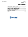
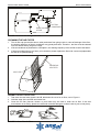
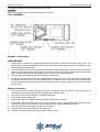
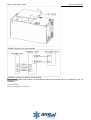
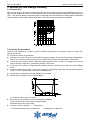
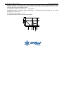
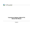
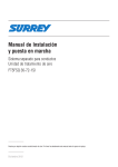
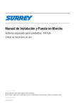
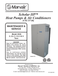
MANUAL DE INSTALACION
Evaporadora Sopladora 'MVA' con Condensadora 'MOV' - Blue Star
Part 4 Installation .................................................................................................................. 57
MCAC-UTSM-2008-02
Installation
Part 4
Installation
1. INDOOR UNIT INSTALLATION ................................. 58
2. CONDENSING UNIT INSTALLATION ........................ 67
3. Vacuum dry and leakage checking .......................... 69
4. Additional charge of refrigerant............................... 71
5. Drain pipe connection .............................................. 72
6. Wiring........................................................................ 73
7. Test operation........................................................... 74
INDOOR UNIT INSTALLATION
MCAC-UTSM-2008-02
1. INDOOR UNIT INSTALLATION
GENERAL INFORMATION
This Modular Air Handler provides the flexibility for installation in any upflow or horizontal application, See
Figure 1. The direct drive motors provide a selection of air volume to match any application.
The unit can be positioned for bottom return air in the upflow position, left return in the horizontal position.
Top and side power wiring and control Wiring, accessible screw terminals for control wiring all combine to
make the installation easy, and minimize installation cost.
FIGURE 1: Typical Applications with MVA3 Multi-Position Coils
INSPECTION
As soon as a unit is received, it should be inspected for possible damage during transit. Also, before
installation the unit should be checked for screws or bolts, which may have loosened in transit. There are no
shipping or spacer brackets which need to be removed.
Also check to be sure all accessories and coils are available, installation of these accessories or field
conversion of the unit should be accomplished before setting the unit in place or connecting any wiring,
electric heat, ducts or piping.
CLEARANCES
1.
2.
3.
4.
Refrigerant piping and connections- minimum12" recommended.
Maintenance and servicing access- minimum36" from front of unit recommended for blower motor/coil
replacement.
Condensate drain line.
Filter removal - minimum 36" recommended.
LOCATION
Location is usually predetermined. Check with owner's or dealer's installation plans, if location has not been
decided, consider the following in choosing a suitable location.
1. Select a location with adequate structural support, space for service access, clearance or air return and
supply duct connections.
2. Use hanging brackets to waft mount unit as shown below.
3. Normal operating sound levels may be objectionable if the air handler is placed directly over some
rooms such as bedrooms, study, etc.
4. Precautions should be taken to locate the unit and ductwork so that supply air does not short circuit to
the return air.
5. Select a location that will permit installation of condensate line to an open drain.
MCAC-UTSM-2008-02
INDOOR UNIT INSTALLATION
NOTE: When the coil is installed in a draw-thru application, it is recommended to trap the primary and
secondary drain line. If the secondary drain line is not used, it must be capped. The coil is provided with a
secondary drain, it should be piped to a location that will give the occupant a visual warning that the primary
drain is clogged. If the secondary drain is not used it must be capped.
6. When an evaporator coil is installed in an attic or above a finished ceiling, an auxiliary drain pan should
be provided under the coil as is specified by most local building codes.
7. Proper electrical supply must be available.
8. Clearances must also be taken into consideration, and provided
for as follows:
A. Refrigerant piping and connections are located in the front.
B. Maintenance and servicing through the front or access side of unit with both sides and rear of unit
having zero inch clearance.
C. Condensate drain lines are connected in the front (clear of filter).
D. Filter removal.
E. When no electric heat is used, the unit as well as all duct work and plenum are designed for zero
clearance to combustible materials.
DUCT CONNECTIONS
Air supply and return may be handled in one of several ways best suited to the installation (See Figure 3 for
dimensions for duct inlet and outlet connections).
FIGURE 2: Plenum Clearances
FIGURE 3: Dimensions and Duct Sizes
The vast majority of problems encountered with combination cooling systems can be linked to improperly
designed or installed duct systems, it is therefore highly important to the success of an installation that the
duct system be properly designed and installed.
Use flexible duct collars to minimize the transmission of vibration/noise into the conditioned space.
Where return air duct is short, or where sound is liable to be a problem, sound absorbing glass fiber should
be used inside the duct. Insulation of duct work is a must where it runs through an uncooled space during the
cooling season. The use of a vapor barrier is recommended to pre-Vent absorption of moisture from the
surrounding air into the insulation. The supply air duct should be properly sized by use of a transition to
INDOOR UNIT INSTALLATION
MCAC-UTSM-2008-02
match unit opening. All ducts should be suspended using flexible hangers and never fastened directly to the
structure. This unit is not designed for non-ducted (freeblow) applications.
Duct work should be fabricated and installed in accordance with local and/or national codes.
DRAIN CONNECTIONS
All drain lines should be trapped a minimum of three inches, should be pitched away from unit drain pan and
should be no smaller than the coil drain connection.
CAUTION
Drain connection should be hand-tightened, plus no more than 1/16 turn.
Horizontal drain cutout in the center access panel should be removed by using a utility knife. DO NOT TRY
TO KNOCK OUT.
Route the drain line so that it does not interfere with accessibility to the coil, air handling system or filter and
will not be exposed to freezing temperatures. See Figures 1,2 and 3.
NOTE: When the coil is installed in an attic or above a finished ceiling, an auxiliary drain pan should be
provided under the coil as is specified by most local building codes.
Coils should be installed level or pitched slightly toward the drain end. Suggested pitch should not exceed1/4
inch per foot of coil.
The coil is provided with a secondary drain that should be trapped and piped to a location that will give the
occupant a visual warning that the primary drain is clogged. If the secondary drain is not used it must be
capped.
The drain pan connections are designed to ASTM Standard D 2466 Schedule 40. Use 3/4" PVC or steel
threaded pipe. Since the drains are not subject to any pressure it is not necessary to use Schedule 40 pipe
for drain lines.
It is recommended that all drain connections be sealed with teflon tape or equivalent.
ORIFICE INSTALLATION
A standard orifice is preinstalled in the unit and is marked on the unit dataplate. Refer to the outdoor unit
instruction and application data to determine the proper orifice required for your particular system
combination and piping conditions. If the orifice sizes match, nothing further is required and the refrigerant
lines may be connected per the outdoor unit instruction. However, if another orifice should be used, change
the orifice in the coil with the following procedure:
CAUTION
This fitting is a right-hand thread, turn counter-clockwise to remove.
1. Remove the liquid line fitting using 3/4" wrenches, and remove the preinstalled orifice with a small
diameter wire or paper clip.
2. Remove the new orifice from the packet and verify that it is the correct number required. Install this
orifice with the rounded end toward the coil and the flat end outward per Figure 4.
3. Thread the liquid line fitting back in place on the coil. Tighten the fitting hand tight and turn an additional
I/8 turn to seal.
MCAC-UTSM-2008-02
INDOOR UNIT INSTALLATION
LI QUID LINE
SW IVEL COU PLIN G
F LAT END
ORIFICE
ROUNDED END
NUT
FIGURE 4: Orifice InstaIlation
CAUTION
Use wrenches to turn fittings. Using pliers will cause internal damage to the fitting.
NOTE: This procedure should be done within 2 minutes to keep air and contaminates from entering the coil.
If the orifice cannot be replaced and the coil resealed within 2 minutes, then it should be temporarily closed
to air using masking tape (short term delay') or plugging/capping (long term delay). There is no need to
purge the coil if this procedure is done within the time limit.
4. Mark the data plate with the orifice installed.
REFRIGERANT LINE CONNECTION
Maximum pipe length
Check whether the height drop between the indoor unit and outdoor unit, the length of refrigerant pipe, and
the number of the bends meet the following requirement:
The max height drop…………………………………………………………………………10m
(if the connecting pipe is more than 10m,you had better put the outdoor unit over above the indoor unit )
the length of refrigerant pipe ………………………………………………………………..less than 30m
Locating the condenser as close as possible to the evaporator will increase the system capacities by
reducing the line set refrigerant pressure drop, and will make the system less susceptible to liquid migrations
due to less refrigerant charge
See the outdoor unit installation instructions for the procedure to install field supplied tubing for systems with
sweat fittings.
Connect lines as follows:
NOTE: Route the refrigerant lines to the coil in a manner that will not obstruct service access to the coil, air
handling system or filter.
1. Removing the bottom condenser, push down the front cover of pipe.
2. Braze the suction line and the liquid line. See figure 5.
3. Attach the front cover of pipe to bottom condenser, re-attach the bottom condenser.
4. Install supplied grommets on both the suction and liquid lines to complete the air seat.
Lines should be sound isolated by using appropriate hangers or strapping. When field supplied lines are
used be sure to insulate the liquid line under any conditions where the ambient temperature is greater than
the liquid line temperature.
INDOOR UNIT INSTALLATION
MCAC-UTSM-2008-02
PU SH DOWN
FR ONT COVE R
OF PIPE
BOTTOM
CONDEN SER
FIGURE 5:Connect the Refrigerant Line
CLEANING THE AIR FILTER
1.
2.
3.
The air filter can prevent the dust or other particulate from going inside .In case of blockage of the filter ,
the working efficiency of the air conditioner may greatly decrease .Therefore , the filter must be cleaned
once two weeks during long time usage.
If the air conditioner is positioned in a dust place , the cleaning frequency of the air filter must be increased .
If the accumulated dust is too heavy to be cleaned, please replace the filter with a new one(replaceable
air filter is an optional fitting).
B
COVER FOR
AIR FILTE R
AI R FILTER
A
FIGURE 6: Remove The Air Filter
1. Tear down the two bolts signed A and B, take down the cover for air filter, see in Figure 6.
2. Hold the edge of the air filter and extract out .
3. Clean the air filter (Vacuum cleaner or pure water may be used to clean the air filter. If the dust
accumulation is too heavy, please use soft brush and mild detergent to clean it and dry out in cool place) .
FIGURE 7: Clean The Air Filter
MCAC-UTSM-2008-02
INDOOR UNIT INSTALLATION
4. Install the air filter in the reverse order of step 1 and 2.
CAUTION
Do not dry out the air filter under direct sunshine or with fire.
COIL ASSEMBLY
FIGURE 8: Coil Assembly
MAINTENANCE
1.
2.
3.
4.
Filters must be cleaned or replaced when they become dirty. Inspect at least once per month. The
frequency of cleaning depends upon the hours of operation and the local atmospheric conditions. Clean
filters keep unit efficiency high.
If the coil needs to be cleaned or replaced, it should be washed with Calgon coil clean (mix one part Coil
clean to seven parts water). Allow solution to remain on coil for 30 minutes before rinsing with clean
water. Solution should not be permitted to come in contact with painted surfaces.
The bearings of the blower motor are permanently lubricated.
During the cooling season check the condensate drain lines to be sure that condensate is flowing from
the primary drain but not from the secondary drain, if condensate ever flows from the secondary drain
the unit should be promptly shut off and the condensate pan and drains cleaned to insure a free flowing
primary drain.
Wiring Connection
1.
2.
3.
4.
5.
1)
2)
3)
To avoid the electric shock, please link the air conditioner with the ground. The plug in the air
conditioner has joined the ground wiring, please don't change it freely.
The power socket is used as the air conditioner specially.
Don't pull the power wiring hard.
When linking the air conditioner with the ground, observe the local rules.
If necessary, use the power fuse or the circuit, breaker or the corresponding scale ampere. When
installing or repair the air condition, relate to system wiring, please operating as follows:
Tear down the two bolts signed A and B, see in Figure 6.
Hold the edge of the top condenser and extract out.
Install the top condenser in the reverse order of step 1 and 2.
INDOOR UNIT INSTALLATION
MCAC-UTSM-2008-02
FIGURE 9:Remove The Top Condenser
FIGURE10: Cooling only System Wiring Diagram
Suggestion: thermostat choose non-programmed electrical thermostat series of Honeywell, such as
TH5220D
COOLING&HEATING
Cooling & Heating System Wiring Diagram
MCAC-UTSM-2008-02
INDOOR UNIT INSTALLATION
NOTE: L1 must be connected with 4, or the system will be damaged.
Suggestion: thermostat choose non-programmed electrical thermostat series of Honeywell, such as
TH5220D
LED DISPLAY
The control would display any fault code that is currently active using the LED. The control will display the fault code, when the LEDS are
flashing quickly, there is something wrong with the system. Refer to below table for detail fault code.
TEMPERATURE SENSOR
The unit have two temperature sensors, which are called T1 and T2, T2 means pipe temperature sensor, T1 means indoor unit
circumstance temperature sensor. When the temperature sensor was damaged, the system would closed and the LED would flashing.
Operational Fault codes
NOTE: X MEANS LED OFF,☆ MEANS LED QUICK FLASH
INDOOR UNIT INSTALLATION
MCAC-UTSM-2008-02
COOLING ONLY ELECTRICAL WIRING GAUGE
Capacity(Btu/h)
Power
Input Current Fuse
30000
36000
48000
Phase
Single
Three
Frequency/Voltage
220~240-50-1
380-50-3
60000
Lines Gauge
Indoor unit(A)
5
5
5
5
Indoor Unit Power
Line
Line Quantity
3
3
3
3
Line Diameter(AWG)
18
18
18
18
Outdoor Unit Power
Line
Line Quantity
3
5
5
5
Line Diameter(AWG)
14
14
14
14
Outdoor-Indoor
Signal Line
Line Quantity
2
2
2
2
Line Diameter(AWG)
18
18
18
18
Thermostat Signal
Line
Line Quantity
4
4
4
4
Line Diameter(AWG)
18
18
18
18
36000
48000
60000
TABLE2: Wiring Gauge
COOLING & HEATING ONLY ELECTRICAL WIRING GAUGE
Capacity(Btu/h)
Power
Input Current Fuse
Phase
Frequency/Voltage
30000
Single
Three
220~240-50-1
380-50-3
Lines Gauge
Indoor unit(A)
5
5
5
5
Indoor Unit Power
Line
Line Quantity
3
3
3
3
Line Diameter(AWG)
18
18
18
18
Outdoor Unit Power
Line
Line Quantity
3
5
5
5
Line Diameter(AWG)
14
14
14
14
Outdoor-Indoor
Signal Line
Line Quantity
3
3
3
3
Line Diameter(AWG)
18
18
18
18
Thermostat Signal
Line
Line Quantity
5
5
5
5
Line Diameter(AWG)
18
18
18
18
TABLE3: Wiring Gauge
MCAC-UTSM-2008-02
CONDENSING UNIT INSTALLATION
2. CONDENSING UNIT INSTALLATION
TYPICAL INSTALLATION
TO
POWER
SUPPLY
TO
INDOOR
BLOWER
24 V c
o n tr o
l s ig n
WEATHERPROOF
DISCONNECT
SWITCH
al
TO
COIL
Chart 18
Seal opening(s) with
permagumor equivalent
NOTE: All outdoor wiring must be weatherproof
INSTALLATION PRECAUTION
To install properly, please read this manual at first.
The air conditioner must be installed by qualified persons.
When all the installation work is finished, please turn on the power only after a thorough check.
No further announcement if there is any change of this manual caused by product improvement.
Note: The installer should illustrate to users how to correctly use and maintain the air-conditioner, as well as
remind users to carefully read and keep both Installation Manual and Owner's Manual well.
Notes Before Installation
1. Select the correct carry-in path.
2. Move this unit as originally packaged as possible.
3. f the air conditioner is installed on a metal part of the building, it must be electrically insulated according
to the relevant standards to electrical appliances.
4. Installation work must be performed in accordance with the national wiring Standards by authorized
personnel only.
INSTALLATION PLACE
The Outdoor Unit
There is enough room for installation and maintenance.
The air outlet and the air inlet are not impeded, and cannot be reached by strong wind.
The place is dry and ventilative.
The support is flat and horizontal and can stand the weight of the outdoor unit. And no additional noise or
vibration.
Your neighborhood will not feel uncomfortable with the noise or expelled air.
There is no leakage of combustible gas.
It is easy to install the connecting pipe or cables
CONDENSING UNIT INSTALLATION
MCAC-UTSM-2008-02
Cautions Location in the following places may cause malfunction of the machine. (If unavoidable, please
consult your local dealer.)
a. There exists petrolatum.
b. There is salty air surrounding(near the coast).
c. There is caustic gas(the sulfide, for example) existing in the air (near a hot spring).
d. The Volt vibrates violently(in the factories).
e. In buses or cabinets.
f. In kitchen where it is full of oil gas.
g. There is strong electromagnetic wave existing.
h. There are inflammable materials or gas.
i. There is acid or alkaline liquid evaporating.
j. Other special conditions.
Note: remark per EMC Directive 89/336/EMC for to prevent flicker impressions during the start of the
compressor (technical process).
Following installation conditions apply.
1. The power connection for the air conditioner has to be done at the main power distribution, the
distribution has to be of a low impedance, normally the required impedance reaches at a 32A fusing
point.
2. no other equipment has to be connected with the power line.
3. for detailed installation acceptance, please refer to your contact with the power supplier if restrictions do
apply for products like washing machine, air conditioner or electrical ovens.
4. for power details of the air conditioner, refer to the rating plate of the product.
5. for any question contact your local dealer.
MCAC-UTSM-2008-02
Vacuum dry and leakage checking
3. Vacuum dry and leakage checking
3.1 Vacuum Dry
Use vacuum pump to change the moisture (liquid) into steam (gas) in the pipe and discharge it out of the
pipe to make the pipe dry. Under one atmospheric pressure, the boiling point of water(steam temperature) is
100℃. Use vacuum pump to make the pressure in the pipe near vacuum state, the boiling point of water falls
relatively. When it falls under outdoor temperature, the moisture in the pipe will be vaporized.
3.2 Vacuum dry procedure
There are two methods of vacuum dry due to different construction environment: common vacuum dry,
special vacuum dry.
3.2.1Common vacuum dry procedure
l Vacuum dry (for the first time)---connect the all-purpose detector to the inlet of liquid pipe and gas pipe,
and run the vacuum pump more than two hours (the vacuum pump should be below -755mmHg)
l If the pump can’t achieve below -755mmHg after pumping 2 hours, moisture or leakage point will still
exist in the pipe. At this time, it should be pumped 1 hour more.
l If the pump can’t achieve -755mmHg after pumping 3 hours, please check if there are some leakage
points.
l Vacuum placement test: place 1 hour when it achieves -755mmHg, pass if the vacuum watch shows no
rising. If it rises, it shows there’s moisture or leakage point.
l Vacuuming from liquid pipe and gas pipe at the same time.
l Sketch map of common vacuum dry procedure
l
l
.
3.2.2 Special vacuum dry procedure
This vacuum dry method is used in the following conditions:
There’s moisture when flushing the refrigerant pipe.
Rainwater may enter into the pipe.
Vacuum dry for the first time ······ 2h pumping
3.2.3 Vacuum destroy for the second time ······ Fill nitrogen to 0.5Kgf/cm2
Vacuum dry and leakage checking
MCAC-UTSM-2008-02
Because nitrogen is for drying gas, it has vacuum drying effect during vacuum destroy. But if the
moisture is too much, this method can’t dry thoroughly. So, please pay more attention to prevent water
entering and forming condensation water.
3.2.4 Vacuum dry for the second time-------1h pumping
Determinant: Pass if achieving below -755mmHg. If -755mmHg can’t be achieved in 2h, repeat
procedure 5.2.3 and 5.2.4.
3.2.5 Vacuum placing test --------1h
3.2.6 Sketch map of special vacuum dry procedure.
MCAC-UTSM-2008-02
Additional charge of refrigerant
4. Additional charge of refrigerant
When the length of the one-way pipe is less than 5m, additional refrigerant charge is unnecessary after
vacuuming.
When the length of one-way pipe is over 5m, the additional charge quantity is as follows:
Calculation method: (unit in gram)
Refrigerant
R22
Liquid diameter(mm/inch)
Unit amount (g/m)
Formula
Φ6.35(1/4”)
30
(L-5)×30
Φ9.53(3/8”)
65
(L-5)×65
Φ12.7(1/2”)
90
(L-5)×90
Remark:1. The additional refrigerant charge is simply related with the liquid pipe diameter.
2. In the up formula, “L” means total length of liquid pipe(unit: m).
Drain pipe connection
MCAC-UTSM-2008-02
5. Drain pipe connection
5.1 Install the indoor unit drain pipe
The outlet has PTI screw bread, Please use sealing materials and pipe sheath (fitting) when connecting
PVC pipes.
CAUTIONS
l
l
l
l
l
l
The drain pipe of indoor unit must be heat insulated, or it will condense dew, as well as the connections
of the indoor unit.
Hard PVC binder must be used for pipe connection, and make sure there is no leakage.
With the connection part to the indoor unit, please be noted not to impose pressure on the side of indoor
unit pipes.
When the declivity of the drain pipe downwards is over 1/100, there should not be any winding.
The total length of the drainpipe when pulled out traversely shall not exceed 20m, when the pipe is too
long, a prop stand must be installed to prevent winding.
Refer to the figures on the right for the installation of the pipes.
1.5m~2m
Put as deep as possible
(about 10cm)
Bend
S shape
Insulating Downward declivity
material lower than 1/100
5.2 Drainage test
Downward declivity
lower than 1/100
Check whether the drainpipe is unhindered
New built house should have this test done before paving the ceiling.
VP30
Test operation
MCAC-UTSM-2008-02
7. Test operation
Note: To avoid personal injury or death, do not supply power to unit with compressor terminal-box cover
removed.
Be sure field wiring complies with local and national fire, safety, and electrical codes, and voltage to system
is within limits shown on unit-rating plate. Contact local power company for correction of improper voltage.
7.1 The test operation must be carried out after the entire installation has been completed.
7.2 Please confirm the following points before the test operation:
l The indoor unit and outdoor unit are installed properly.
l Tubing and wiring are correctly completed.
l The refrigerant pipe system is leakage-checked.
l The drainage is unimpeded.
l The heating insulation works well.
l The ground wiring is connected correctly.
l The length of the tubing and the added stow capacity of the refrigerant have been recorded.
l The power voltage fits the rated voltage of the air conditioner.
l There is no obstacle at the outlet and inlet of the outdoor and indoor units.
l The gas-side and liquid-side stop valves are both opened.
l The air conditioner is pre-heated by turning on the power.
7.3 Test operation
Set the air conditioner under the mode of “cooling”, and check the following points as the “Owner’s Manual”.
If there is any malfunction, please refer to chapter “Troubles and Causes”in the “Owner’s Manual”.
7.3.1 The indoor unit
l Whether the room temperature is adjusted well.
l Whether the indicator lights normally.
l Whether the drainage is normal.
l Whether there is vibration or abnormal noise during operation.
7.3.2 The outdoor unit
l Whether there is vibration or abnormal noise during operation.
l Whether the generated wind, noise, or condensed water by the air conditioner have influenced your
neighborhood.
l Whether any of the refrigerants is leaked.
Cautions:
1.
2.
A protection device delays the start of compressor for about 3 minutes when it is restarted immediately
after switching on the power.
To prevent compressor damage or personal injury, observe the following:
Do not overcharge system with refrigerant.
Do not operate unit in a vacuum or at negative pressure.
Do not disable low-pressure switch.