1
Excel 50
MMI
USER GUIDE
Copyright © 2001 Honeywell Inc. • All Rights Reserved
EN2B-0222GE51 R1101
EXCEL 50 USER GUIDE
Trademark Information
Echelon, LON, LONMARK, LONWORKS, LonBuilder, NodeBuilder, LonManager,
LonTalk, LonUsers, LonPoint, Neuron, 3120, 3150, the Echelon logo, the
LONMARK logo, and the LonUsers logo are trademarks of Echelon Corporation
registered in the United States and other countries. LonLink, LonResponse,
LonSupport, and LonMaker are trademarks of Echelon Corporation.
EN2B-0222GE51 R1101
ii
EXCEL 50 USER GUIDE
CONTENTS
About This User Guide...................................................................................... vii
Operator's Terminal ............................................................................................ 1
Keyboard........................................................................................................ 1
Basic Function Keys ................................................................................................... 2
Resetting ............................................................................................................ 3
Fast-Access Keys ....................................................................................................... 4
LCD Display ................................................................................................... 4
Initialization and Entry ........................................................................................ 5
Initialization Sequence ................................................................................... 5
Entry Sequence.............................................................................................. 5
Access Levels ............................................................................................................. 6
Password Procedure................................................................................................... 6
Modifying the Password ..................................................................................... 7
The Plants Fast-Access Key............................................................................... 8
Plant Components (Data-Point Groups)......................................................... 8
Data-Points ................................................................................................................. 9
Data-Point Attributes ........................................................................................ 10
The Time Programs Fast-Access Key.............................................................. 11
Time Programs............................................................................................. 11
Time Schedules ........................................................................................................ 12
The "Today" Time Schedule............................................................................. 13
The 'Daily' Time Schedule ................................................................................ 15
Deleting and Copying/Creating Daycycles ....................................................... 17
Deleting a Switch-Point .................................................................................... 18
Creating a Switch-Point .................................................................................... 19
The 'Weekly' Time Schedule ............................................................................ 19
The 'Annual' Time Schedule............................................................................. 21
Creating Additional Annual Time Schedules .................................................... 23
Navigating through Annual Time Schedules .................................................... 23
Deleting Annual Time Schedules ..................................................................... 23
The System Topics Fast-Access Key............................................................... 24
Types of Data-Points.................................................................................... 25
Types of Physical Data-Points .................................................................................. 25
Types of Pseudo Data-Points ................................................................................... 26
Types of Remote Data-Points................................................................................... 26
Maintenance ................................................................................................ 26
Manual Operation ..................................................................................................... 26
Points in Trend.......................................................................................................... 28
Trend Buffer.............................................................................................................. 29
iii
EN2B-0222GE51 R1101
EXCEL 50 USER GUIDE
Hours Run................................................................................................................. 30
DDC Parameters....................................................................................................... 31
System Configuration ...................................................................................31
System Info............................................................................................................... 32
System Time ............................................................................................................. 33
Daylight Saving................................................................................................. 33
Hardware Interface Configuration ............................................................................. 34
C-Bus Configuration ......................................................................................... 35
LON-Bus Configuration .................................................................................... 36
B-Port ............................................................................................................... 36
Modem ............................................................................................................. 36
M-Bus ............................................................................................................... 37
Flash EPROM ........................................................................................................... 38
Saving the Application ...................................................................................... 39
Erasing the Flash Memory................................................................................ 39
Showing the Application ................................................................................... 40
Bus-Wide Access...................................................................................................... 40
Remote Login ................................................................................................... 41
Remote Logoff.................................................................................................. 42
Remote Alarms On/Off ..................................................................................... 42
DDC Times ............................................................................................................... 42
The Alarms Fast-Access Key............................................................................43
Alarm Buffer .................................................................................................43
Point in Alarm ...............................................................................................44
Critical / Non-Critical Alarms.........................................................................44
Alarm Attributes ........................................................................................................ 44
System Alarms Description....................................................................................... 44
Min. / Max. Limit Monitoring ...................................................................................... 44
Powering Up / Resetting the Controller ...........................................................48
Hardware Interface Configuration.................................................................49
Choosing an Application Manually................................................................50
Downloading an Application .........................................................................52
Setting Up the Test Mode with Default Data-Point Names ...........................53
Appendix 1: Data-Point Attributes....................................................................57
Analog Input Data-Point Attributes ...............................................................57
Analog Output Data-Point Attributes.............................................................58
Digital Input Data-Point Attributes ................................................................59
Digital Output Data-Point Attributes..............................................................59
Pseudo Analog Data-Point Attributes ...........................................................60
Pseudo Digital Data-Point Attributes ............................................................60
Remote Analog Data-Point Attributes...........................................................61
Remote Digital Data-Point Attributes ............................................................61
Totalizer Data-Point Attributes......................................................................62
EN2B-0222GE51 R1101
iv
EXCEL 50 USER GUIDE
M-Bus Data-Point Attributes......................................................................... 62
Individual Data-Point Attributes .................................................................... 63
Data-Point Name ...................................................................................................... 63
Appending the Controller's Number to the Data-Points' Names....................... 63
The 'Operating Mode' Attribute ................................................................................. 63
Optimizing a Switch-Point ......................................................................................... 64
v
EN2B-0222GE51 R1101
EXCEL 50 USER GUIDE
ABOUT THIS USER GUIDE
This User Guide describes operation of the Excel 50 MMI for configurable
applications with Version 2.05 (or higher) firmware. It focuses on changes in
operation with respect to Version 2.04.
Version 2.05 introduces a number of significant software improvements facilitating
operation of the MMI. These improvements are essentially as follows:
• The number of keystrokes necessary to access important information and/or to
reconfigure applications has been considerably reduced.
• Moving from screen to screen has been simplified.
• The utilization of space in the display screen has been optimized.
Additionally, one important hardware improvement should also be mentioned:
• The display screen has been equipped with back-lighting to enhance
readability.
vii
EN2B-0222GE51 R1101
EXCEL 50 USER GUIDE
EN2B-0222GE51 R1101
viii
EXCEL 50 USER GUIDE
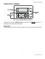
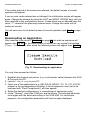
OPERATOR'S TERMINAL
Fig. 1. Excel 50 Man-Machine Interface
The Excel 50 controller's MMI (Man-Machine Interface, see Fig. 1) consists of a
keyboard and a display described below.
Keyboard
The keyboard has 8 basic function keys and 4 fast-access keys described below.
1
EN2B-0222GE51 R1101
ALARM DESCRIPTION
EXCEL 50 USER GUIDE
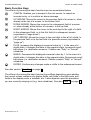
Basic Function Keys
The effects of pressing the basic function keys are summarized below.
CANCEL: Enables you to escape to the root screen, to cancel an
incorrect entry, or to confirm an alarm message.
UP ARROW: Moves the cursor to the previous field of a screen or, when
already at the top of a screen, to the bottom field.
DOWN ARROW: Moves the cursor to the subsequent field of a screen
or, when already at the bottom of a screen, to the top field.
RIGHT ARROW: Moves the cursor to the next digit to the right of a field,
to the subsequent field, or to the first field of a subsequent screen
(equivalent to "page down").
LEFT ARROW: Moves the cursor to the next digit to the left of a field, to
the previous field, or to the last field of a previous screen (equivalent to
"page up").
PLUS: Increases the displayed numerical value by 1. In the case of a
digital state, it changes the state to the opposite state. Increments scroll
bar values (i.e. destination screens). Creates new "Daily" or "Annual"
schedules.
MINUS: Decreases the displayed numerical value by 1. In the case of a
digital state, it changes the state to the opposite state. Decrements scroll
bar values (i.e. destination screens). Deletes existent "Daily" or "Annual"
schedules.
ENTER: Confirms any changes made or shifts to the subsequent screen.
See also section "Resetting" on page 3.
The effects of pressing the basic function keys differs depending upon whether
the current screen contains only display fields, edit fields in the edit mode, edit
fields in the display mode, a scrollbar, etc. It also depends upon the procedure
you are currently carrying out (e.g. time schedules). See also Table 1 on page 3.
EN2B-0222GE51 R1101
2
EXCEL 50 USER GUIDE
Table 1. Effects of Basic Function Keys
screens containing
key
only display
fields
edit fields in
display mode
no effect
goes to
previous field
edit fields in
edit mode
no effect
goes to next
field
no effect
a listbox with
scrollbar
goes to previous field
increments value
no effect
a listbox
without
scrollbar*
no effect, except
increments
for time
scrollbar value
schedules (adds
(screen no.)
a new schedule)
goes to next field
decrements
value
no effect, except
decrements
for time
scrollbar value
schedules (de(screen no.)
letes a schedule)
goes to previous or stays in
goes to previous
pages up
same screen
digit within field
goes to next or stays in same
goes to next digit
pages down
screen
within field
rejects change
escapes to root screen
escapes to root screen
shifts from
confirms value /
no effect
display to edit shifts from edit to
confirms selection
mode
display mode
* Also Plant Components lists, Point Attributes lists, and System Topics submenus
Resetting
NOTE: A reset has a more-severe impact than simply switching off the device:
All RAM data and all configuration codes are lost, and the controller will
therefore have to be re-initialized (see "Powering Up / Resetting the
Controller" on page 48) in order to work with it. You should reset your
Excel 50 MMI only as a preliminary to downloading a new
application.
&
Simultaneously pressing the DOWN ARROW key and the MINUS key
causes a reset.
A reset can also be achieved by pressing the hardware RESET button at the rear
of the controller housing under Terminal Block B.
3
EN2B-0222GE51 R1101
ALARM DESCRIPTION
EXCEL 50 USER GUIDE
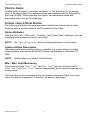
Fast-Access Keys
The use of the fast-access keys is summarized below.
PLANTS: Displays a list of the selected plant components and their
current states.
TIME PROGRAMS: Displays a list of configured time programs and
provides all time schedule customization options.
SYSTEM TOPICS: Available only in access level 3. Provides system
settings and application parameters.
ALARMS: Displays alarm information on alarm history, points currently in
an alarm condition, critical alarms, and non-critical alarms.
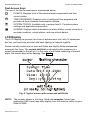
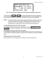
LCD Display
The LCD display can present four lines of alphanumeric text, with 16 characters
per line, and has been provided with back-lighting to improve legibility.
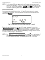
Screen usually contain one or more edit fields and display fields interspersed
among its four lines. The current edit field is indicated by the presence of a
cursor (arrowhead) to the left of it. In the case of edit fields consisting of several
digits, the current digit will be flashing. See Fig. 2.
Fig. 2. Typical screen with cursor and edit fields
NOTE: The screens shown in this User Guide are examples (taken from
application HE01) and may differ slightly from the screens visible on your
Excel 50 MMI.
EN2B-0222GE51 R1101
4
EXCEL 50 USER GUIDE
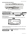
INITIALIZATION AND ENTRY
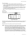
Fig. 3. Initialization and entry sequences
Initialization Sequence
Upon downloading an application into your Excel 50 MMI (see also "Powering Up
/ Resetting the Controller" on page 48), the initialization sequence will begin. This
initialization sequence consists of a series of four screens (see Fig. 3). If the
configuration codes are correct, the initialization sequence should be immediately
followed by the entry sequence (see section "Entry Sequence" on page 5).
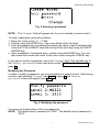
Entry Sequence
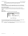
After the application has been downloaded, the entry sequence will begin. The
first screen is the start screen (see Fig. 4).
Fig. 4. The start screen
The start screen includes the name of the application (in this case, HE01) as well
as the current date and time.
If "BW-MMI" appears, this means that the controller offers C-bus access (which
you would need to communicate with modules located on a C-bus). See section
"C-Bus Configuration" on page 36 for more information.
5
EN2B-0222GE51 R1101
ALARM DESCRIPTION
EXCEL 50 USER GUIDE
NOTE: The two-digit CPU field (in the upper right-hand corner), the date, and
the time will be editable only if you are already in access level 3 (see
section "Access Levels" on page 6).
NOTE: The "Logout" edit field will appear only if you are already in access level
2 or 3 (see section "Access Levels" on page 6).
Selecting the "Password" field will take you to the password procedure (see
section "Password Procedure" on page 6).
Access Levels
The use of three access levels ensures that only authorized personnel can
read/edit sensitive system data. In order to enter access level 1, no password is
necessary, and only those screens accessible at that level will be displayed (see
also Table 2). In order to enter access levels 2 and 3, a corresponding password
must be entered.
Table 2. Access Levels and Corresponding Authorizations
access PLANTS key TIME PROGRAMS SYSTEM TOPICS
level
( )
key ( )
key ( )
1
read only
read only
no effect
2
read only
time schedules
no effect
3
unlimited editing possible
ALARMS key
( )
read only
read only
read only
NOTE: In the following sections, the password procedure will not be repeated.
Refer back to this section for guidance on entering the password.
IMPORTANT
If you have forgotten the level-3 password, please contact your local
Honeywell branch.
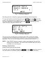
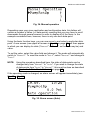
Password Procedure
Upon selecting the "Password" field, the following screen will appear (see Fig. 5
on page 7).
EN2B-0222GE51 R1101
6
EXCEL 50 USER GUIDE
Fig. 5. Entering a password
NOTE: The "Change" field will appear only if you are already in access level 3.
To enter a password, proceed as follows:
1. Move the cursor to the "****" field.
2. Confirm using the ENTER key – the cursor blinks at the first digit.
3. Enter the password by increasing/decreasing the value of each individual digit
using the PLUS or MINUS keys and moving to the next digit using the RIGHT
ARROW key.
4. Upon completion of password entry, confirm using the ENTER key. You can
then leave this screen and return to the start screen using the CANCEL key.
If you wish to modify a password, select the "Change" field. This will take you to
the "Modify password" screen (see also section "Modifying the Password" on
page 7).
Modifying the Password
In order to modify a password, you must already be in access level 3. After having
moved to and selected "Change" (see Fig. 5 on page 7), the "Modify
password" screen will appear (see Fig. 6).
Fig. 6. Modifying the password
You may now modify either of the two passwords.
NOTE: The default level-2 password is "2222". The default level-3 password is
"3333".
7
EN2B-0222GE51 R1101
ALARM DESCRIPTION
EXCEL 50 USER GUIDE
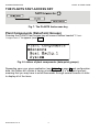
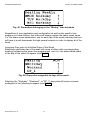
THE PLANTS FAST-ACCESS KEY
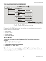
Fig. 7. The PLANTS fast-access key
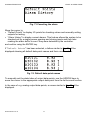
Plant Components (Data-Point Groups)
Pressing the PLANTS fast-access key will cause a listbox headed "Plant
Components" to appear (see Fig. 8).
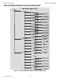
Fig. 8. Listbox of plant components (data-point groups)
Depending upon your given application (see Table 3 on page 9) and configuration
data, this listbox will contain a varying number of items (i.e. data-point groups),
meaning that you may have to scroll downwards through several screens in order
to display all of the items.
EN2B-0222GE51 R1101
8
EXCEL 50 USER GUIDE
items
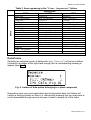
Table 3. Items appearing in the "Plant Components" listbox
AH03
Sensors
AHU_Strategy
Dampers
Energy Recovery
Filters
Heating
Cooling
Humidity
Fans
Heating Circ.
Boiler
Zone1
Zone2
Zone3
Zone4
Alarms
Time Programs
LON
Application
HT02
Sensors
Htg_Strategy
Boiler1
Boiler2
Boiler3
Boiler4
System
Heating Circ.1
Heating Circ.2
Heating Circ.3
Dom. Hot Water
Heat meter
Alarms
Time Programs
LON
HE01
Sensors
Heat Exchg.1
System
Heating Circ.1
Heat Exchg.2
Heating Circ.2
Dom. Hot Water1
Dom. Hot Water2
Pulse meters
M-Bus meters
LON meter
Alarms
Time Programs
LON
Htg_Strategy
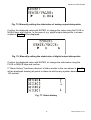
Data-Points
Selecting an individual group of data-points (e.g. "Sensors") will cause a listbox
(including a scrollbar at the right-hand margin) with a corresponding heading to
appear (see Fig. 9).
Fig. 9. Listbox of data-points belonging to a plant component
Depending upon your given application and configuration data, this listbox will
contain a varying number of items (i.e. data-points) meaning that you may have to
scroll downwards through several screens in order to display all of the items.
9
EN2B-0222GE51 R1101
ALARM DESCRIPTION
EXCEL 50 USER GUIDE
NOTE: In the case of listboxes spread out over three or more screens, use of
the scrollbar (the value of which is incremented or decremented with the
PLUS and MINUS keys; see also Table 1 on page 3) can greatly simplify
navigation by allowing the user to skip ahead to the screen of interest.
Data-Point Attributes
Selecting an individual data-point (e.g. OATmp) will cause a series of screens
(viewable in its entirety by scrolling sideways) with a corresponding heading to
appear (see Fig. 10).
Fig. 10. Data-point attributes (first screen of a series)
Depending upon the type and sub-type of the given data-point (see section
"Types of Data-Points" on page 25) this series will consist of a varying number of
screens containing edit fields in which you can specify the data-point's various
different attributes. You will thus have to scroll sideways through several screens
in order to display/configure all of the fields.
NOTE: See "Appendix 1: Data-Point Attributes" on page 57 for an explanation of
the meaning of the expression "data-point attributes", an exhaustive list
of all the possible attributes, their meanings, and how to edit them.
EN2B-0222GE51 R1101
10
EXCEL 50 USER GUIDE
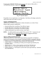
THE TIME PROGRAMS FAST-ACCESS KEY
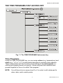
Fig. 11. The TIME PROGRAMS fast-access key
Time Programs
Using the TIME PROGRAMS key, you can assign values (e.g. temperatures) and
states (e.g. "ON" or "OFF") to data-points belonging to a specific time schedule.
These values/states will then become active/inactive at the switch-points (i.e.
starting and stopping times) you specify. Various different time schedules are
grouped together to form a so-called "time program."
NOTE: You will have to be in access level 2 or 3 in order to edit a data-point's
value, state, and/or switch-points.
11
EN2B-0222GE51 R1101
ALARM DESCRIPTION
EXCEL 50 USER GUIDE
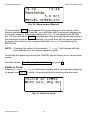
Pressing the TIME PROGRAMS fast-access key will cause a listbox with a
corresponding heading to appear (see Fig. 12).
Fig. 12. Time programs
Depending upon your given application (see Table 4) and configuration data, this
listbox will contain a varying number of items (i.e. time programs) from which to
choose, meaning that you may have to scroll downward to display them all.
Table 4. Items appearing in the "Time Programs" listbox
TP_index
AH03
AHU_Strategy
Heating Circuit
Time Programs
Zone
LON
Application
HT02
Heating Circ.1
Heating Circ.2
Heating Circ.3
Htg_Strategy
Dom. Hot Water
Time Program 1
Time Program 2
Time Program 3
Time Prog Lon 1
Time Prog Lon 2
Time Prog Lon 3
Time Prog Lon 4
Time Prog Lon 5
1
2
3
4
5
6
7
8
9
10
11
12
13
14
15
Remark: See Lizard documentation for defaults.
HE01
Heating Circ.1
Heating Circ.2
Dom. Hot Water1
Dom. Hot Water2
Time Program 1
Time Program 2
Time Program 3
Alarm NonCrit En
Time Prog Lon 1
Time Prog Lon 2
Time Prog Lon 3
Time Prog Lon 4
Time Prog Lon 5
Time Prog Lon 6
Time Prog Lon 7
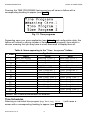
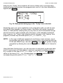
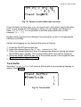
Time Schedules
Selecting an individual time program (e.g. Heating Circ. 1) will cause a
screen with a corresponding heading to appear (see Fig. 13).
EN2B-0222GE51 R1101
12
EXCEL 50 USER GUIDE
Fig. 13. Time schedules belonging to a time program
Regardless of your application and configuration, this listbox will always contain
the same four items (i.e. time schedules) from which to choose, meaning that you
will have to scroll downwards to display the fourth item ("Annual").
The four time schedules are as follows:
•
•
•
•
Today,
Daily,
Weekly, and
Annual.
See also the following sections.
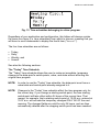
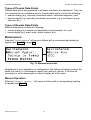
The "Today" Time Schedule
The "Today" time schedule allows the user to make an immediate, temporary
change to the data-point's switch-points, value, and state without affecting the
original time program.
NOTE: In order to use the "Today" time schedule, the data-point must have a
value/state and switch-point already assigned to it.
NOTE: Changes to the "Today" time schedule affect the time program only for
the current day. If you change a starting switch-point, the new starting
switch-point will take effect within 24 hours of the current time. That
means, for example, that a starting switch-point of 10:00 a.m. entered at
10:27 a.m. will activate the temporary changes ONLY AS OF the next
morning. The changed fields are valid for only 24 hours, and are then
automatically deleted after the stopping switch-point has been reached.
13
EN2B-0222GE51 R1101
ALARM DESCRIPTION
EXCEL 50 USER GUIDE
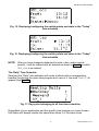
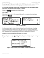
Selecting the "Today" time schedule will cause a listbox with a corresponding
heading (containing the given time program and, next to it, the time schedule) to
appear (see Fig. 14).
Fig. 14. Data-points belonging to the "Today" time schedule
Depending upon your given application and configuration data, as well as upon
the specific time program you have chosen, this listbox will contain numerous
items (i.e. data-points) meaning that you may have to scroll downwards through
several screens in order to display all of the items. In the example considered
here, however, the "Today" time schedule (which belongs to the "Heating" time
program) contains only two data-points (HG1_occ and HG1_tsp).
NOTE: In the case of listboxes spread out over three or more screens, use of
the scrollbar (the value of which is incremented or decremented with the
PLUS and MINUS keys; see also Table 1 on page 3) can greatly simplify
navigation by allowing the user to skip ahead to the screen of interest to
him.
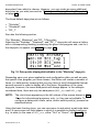
Using the basic function keys, you can now move to and select a particular datapoint. A new screen will then appear in which it is possible to display/configure,
e.g. its state (in the case of HG1_occ, either "Occ" or "Unocc"; see Fig. 15), its
value (in the case of HG1_tsp, a temperature; see Fig. 16), and/or the
corresponding switch-points ("From:" and "To:").
EN2B-0222GE51 R1101
14
EXCEL 50 USER GUIDE
Fig. 15. Displaying/configuring the switch-points and state in the "Today"
time schedule
Fig. 16. Displaying/configuring the switch-points and value in the "Today"
time schedule
NOTE: After you have changed a data-point's state, value, and/or switchpoint(s), it will be marked with an asterisk as shown in Fig. 14, in which
HG1_occ is so marked.
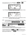
The 'Daily' Time Schedule
Selecting the "Daily" time schedule will cause a listbox with a corresponding
heading (containing the given time program and, next to it, the word "Daily") to
appear (see Fig. 17).
Fig. 17. Daycycles belonging to all four time schedules
Regardless of your application and the specific time program you have chosen,
this listbox will always contain the same three items (i.e. the same three
15
EN2B-0222GE51 R1101
ALARM DESCRIPTION
EXCEL 50 USER GUIDE
daycycles) from which to choose. However, you can create as many additional
daycycles as you wish (see section "Deleting and Copying/Creating Daycycles"
on page 17).
The three default daycycles are as follows:
• "Workday",
• "Weekend", and
• "DP_1".
See also the following section.
The 'Workday', 'Weekend', and 'DP_1' Daycycles
Selecting the "Workday", "Weekend", and "DP_1" daycycles will cause a listbox
with a corresponding heading (containing the given time program and, next to it,
the daycycle) to appear (see Fig. 18 on page 16).
Fig. 18. Data-points displayable/editable in the "Workday" daycycle
Depending upon your given application and configuration data, as well as upon
the specific time program you have chosen, this listbox will contain a number of
items (i.e. data-points) meaning that you may have to scroll downwards through
several screens in order to display all of the items. Regardless of the given
daycycle, however, the same data-points will always appear. In the example
considered here, there are only two data-points (HG1_occ and HG1_tsp).
NOTE: The clock-times appearing in the left column of the screen shown in Fig.
18 are for informational purposes, only, i.e. they are not editable. To
configure a data-point's state, value, and/or switch-point(s), proceed as
described below.
Using the basic function keys, you can now move to and select a particular datapoint. A new screen will then appear in which it is possible to display/configure,
e.g. its state (in the case of HG1_occ, either "Occ" or "Unocc"; see Fig. 19), its
EN2B-0222GE51 R1101
16
EXCEL 50 USER GUIDE
value (in the case of HG1_tsp, a temperature; see Fig. 20 on page 17), its
corresponding switch-point ("Time:"), and/or to optimize it ("ON" or "OFF").
Fig. 19. Displaying/configuring the time, state, and optimization of a datapoint in the "Daily" time schedule
Fig. 20. Displaying/configuring the time, value, and optimization of a datapoint in the "Daily" time schedule
NOTE: If asterisks appear in the "Opt.:" line, this means that the given datapoint is not suitable for optimization and that thus no entry can be made
here (see also section "Optimizing a Switch-Point" on page 64).
Daycycles of this kind will be needed in order to configure the individual days of
the week (see also "Assigning Daycycles to Individual Days of the Week" on page
20) of which the "Weekly" time schedule (see section "The 'Weekly' Time
Schedule" on page 19) is comprised.
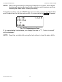
Deleting and Copying/Creating Daycycles
Existent daycycles can be deleted. It is also possible to copy existent daycycles
and then to modify them, thus effectively creating new daycycles.
To delete a daycycle this, go to Fig. 17 (see page 15), move the cursor to the
daycycle to be deleted (e.g. DP_2), press the MINUS key, and confirm the query
appearing in the resultant screen (see Fig. 21). If desired, you can reject the
query using the CANCEL key.
17
EN2B-0222GE51 R1101
ALARM DESCRIPTION
EXCEL 50 USER GUIDE
Fig. 21. Deleting a daycycle
New daycycles are created by copying and modifying existent daycycles.
To copy and modify an existent daycycle, go to Fig. 17 (see page 15), move the
cursor to the daycycle to be copied (e.g. DP_1), press the PLUS key, and confirm
the query appearing in the resultant screen (see Fig. 22). If desired, you can
reject the query using the CANCEL key.
Fig. 22. Creating a daycycle
The copy of the new daycycle is issued the name "DP" to which the lowest
number which has not already been assigned to an existent daycycle will be
appended. Thus, the first new daycycle to be created would be named DP_1.
NOTE: If the "COPY" function is used to create a new daycycle, the next free
daycycle will be assigned. This means that the default daycycle can be
overridden by a new daycycle.
Deleting a Switch-Point
Existent switch-points can be deleted.
To do this, go to the listbox displayed in Fig. 18 (see page 16), move the cursor to
the switch-point to be deleted, press the MINUS key, and confirm the query
EN2B-0222GE51 R1101
18
EXCEL 50 USER GUIDE
appearing in the resultant screen (see Fig. 23). If desired, you can reject the
query using the CANCEL key.
Fig. 23. Deleting a switch-point
Creating a Switch-Point
Switch-points are defined by selecting desired data-points from a list of all
possible data-points valid for the given daycycle and then editing the
corresponding value/state and clock-times (i.e. switch-points).
To do this, move to the listbox displayed in Fig. 18 and press the PLUS key. In the
resultant screen (see Fig. 24), you will be presented with a list of all possible datapoints valid for this daycycle.
Fig. 24. Creating a switch-point
Move the cursor to the data-point for which switch-points are to be defined and
confirm.
A screen resembling Fig. 19 or Fig. 20 (as the case may be) will then appear. Edit
the value/state and switch-point(s) as desired and confirm.
The 'Weekly' Time Schedule
Selecting the "Weekly" time schedule will cause a listbox with a corresponding
heading (containing the given time program and, next to it, the word "Weekly") to
appear (see Fig. 25).
19
EN2B-0222GE51 R1101
ALARM DESCRIPTION
EXCEL 50 USER GUIDE
Fig. 25. Parameters belonging to the "Weekly" time schedule
Regardless of your application and configuration as well as the specific time
program you have chosen, this listbox will always contain the same seven items
(i.e. the same seven parameters, one for each day of the week) meaning that you
will have to scroll downwards through several screens in order to display all of the
items.
Assigning Daycycles to Individual Days of the Week
Selecting a particular day of the week will cause a listbox with a corresponding
heading (containing the given time program and, next to it, the abbreviated name
of the day of the week) to appear (see Fig. 26).
Fig. 26. Daycycles assignable to days of the week
Selecting the "Workday", "Weekend", or "DP_1" daycycles will cause a screen
analogous to the following to appear (see Fig. 27).
EN2B-0222GE51 R1101
20
EXCEL 50 USER GUIDE
Fig. 27. Confirming assignment of a daycycle to days of the week
Upon confirming your selection, you will be returned to the previous screen so
that you may continue assigning daycycles to the other days of the week.
By assigning daycycles (see section "The 'Workday', 'Weekend', and 'DP_1'
Daycycles" on page 16) to the individual days of the week, you effectively define
the make-up of a typical week. Week after week throughout the year, a predetermined daycycle will then be effective on the corresponding day of the week.
Example 1: The same daycycle (namely "Workday") could be assigned to
Monday through Friday, while a different daycycle (i.e. "Weekend") could be
assigned to Saturday and Sunday.
Example 2: Let's assume that, for some reason, Thursday requires a different
daycycle. A specially-created daycycle (DP_2) could therefore be assigned it
while the "Workday" daycycle is assigned to Monday, Tuesday, Wednesday, and
Friday.
NOTE: In the case of XL50 MMI's connected only to a C-bus, the name of
specially-created daycycles can be changed only via a PC or central.
The 'Annual' Time Schedule
Selecting the "Annual" time schedule will cause a screen with a corresponding
heading (containing the given time program and, next to it, the word "Annual") to
appear (see Fig. 28).
21
EN2B-0222GE51 R1101
ALARM DESCRIPTION
EXCEL 50 USER GUIDE
Fig. 28. Parameters belonging to the "Annual" time schedule
Regardless of your application and the specific time program you have chosen,
this screen will always contain two lines ("From:" and "To:") in which you can
enter the initial day and final day of the period of time to which a particular
daycycle should be assigned. To enter the desired daycycle, move the cursor to
the bottom line (in which the asterisks are located) and confirm. The following
screen will then appear (see Fig. 29).
Fig. 29. Assigning a daycycle to a time period
Depending upon the number of daycycles you have deleted and/or created, this
listbox will contain a varying number of daycycles from which to choose, meaning
that you may have to scroll downwards through several screens in order to display
all of the items.
Upon successful completion of the daycycle assignment process, a screen
analogous to the following (see Fig. 30) will then appear.
EN2B-0222GE51 R1101
22
EXCEL 50 USER GUIDE
Fig. 30. Successful completion of the daycycle assignment process
This procedure (Fig. 28 to Fig. 30) may now be repeated as often as desired in
order to assign individual daycycles to additional periods of time throughout the
year. When the process is complete, the result is an annual time schedule.
NOTE: The time periods of the annual program should not overlap. If your time
periods do overlap, the ends of individual periods will be truncated to
correspond to the starting times of subsequent time periods. Time
periods wholly included within other time periods will be deleted.
Creating Additional Annual Time Schedules
It is possible to repeat the process described in section "The 'Annual' Time
Schedule" for other time programs. This is done using the PLUS key.
Navigating through Annual Time Schedules
It is possible to navigate through the various different annual time schedules you
have created by scrolling sidewise using the LEFT ARROW and RIGHT ARROW
keys.
Deleting Annual Time Schedules
Existent annual time schedules can be deleted using the MINUS key.
23
EN2B-0222GE51 R1101
ALARM DESCRIPTION
EXCEL 50 USER GUIDE
THE SYSTEM TOPICS FAST-ACCESS KEY
Fig. 31. The SYSTEM TOPICS fast-access key
EN2B-0222GE51 R1101
24
EXCEL 50 USER GUIDE
Pressing the SYSTEM TOPICS fast-access key will cause a listbox with a
corresponding heading to appear (see Fig. 32).
Fig. 32. System topics
Regardless of your application or configuration, this listbox will always contain the
same three items from which to choose.
Types of Data-Points
With the Excel 50 MMI, it is possible to obtain information on a total of three
different basic groups of data-points:
•
•
•
•
physical data-points (consisting of five different types);
pseudo data-points (consisting of two different types);
remote data-points (consisting of two different types);
totalizer data-points (e.g. pulse counters, reset input).
NOTE: An additional basic group called "M-bus points" ("M" = "meter bus") will
appear only if your Excel 50 MMI has been equipped with M-bus
modules. See also Table 5 on page 35.
Types of Physical Data-Points
Physical data-points are inputs and outputs directly connected to a hardware
device such as a sensor or an actuator. The Excel 50 MMI is equipped to handle
a maximum of 22 physical data-points. Physical data-points include the following:
• analog inputs (i.e. measured values received from field devices),
• analog outputs (i.e. modulating or floating control signals generated by the
controller, itself),
• digital inputs (i.e. state or alarm signals received from field devices),
• digital outputs (i.e. commands issued by the controller, itself), and
• totalizer signals (i.e. reset inputs or pulse meter inputs generated by / received
from field devices).
25
EN2B-0222GE51 R1101
ALARM DESCRIPTION
EXCEL 50 USER GUIDE
Types of Pseudo Data-Points
Pseudo data-points are generated in software to achieve the application. They are
not connected to any hardware device. Pseudo data-points include the following:
• pseudo analog (e.g. internally calculated values, calculated setpoints,) and
• pseudo digital (e.g. internally calculated commands, e.g. point alarms, pump
exercise, etc.).
Types of Remote Data-Points
Remote data-points include the following:
• remote analog (e.g. outside air temperature, heat demand, etc.) and
• remote digital (e.g. alarm reset, alarm outputs, etc.).
Maintenance
Selecting "Maintenance" will cause a listbox with a corresponding heading to
appear (see Fig. 33 on page 26).
Fig. 33. Maintenance tasks
Regardless of your application or configuration, this listbox will always contain the
same five items (i.e. maintenance tasks) from which to choose. It will thus be
necessary to scroll downwards in order to display all of the items.
Manual Operation
Selecting "Manual Operat." will cause a listbox with a corresponding heading
to appear (see Fig. 34).
EN2B-0222GE51 R1101
26
EXCEL 50 USER GUIDE
Fig. 34. Manual operation
Depending upon your given application and configuration data, this listbox will
contain a number of items (i.e. data-points) meaning that you may have to scroll
downwards through several screens in order to display all of the items. In the
example considered here, however, there is only one such data-point.
Using the basic function keys, you can now move to and select a particular datapoint. A new screen (see upper left screen in Fig. 80 on page 58) will then appear
in which you can display its state ("Manual" or "Auto", as the case may be) and
value.
To set the value, select the value field and change it. The mode will automatically
switch to "Manual". To reset the mode to "Auto", select "Manual" and change to
"Auto".
NOTE: Using the procedure described here, the state of data-points can be
changed only from "Manual" to "Auto". If you wish to change the state
of data-points from "Auto" to "Manual", this must be done as described
in "Appendix 1: Data-Point Attributes" on page 57.
If the operating mode is changed, an alarm screen will appear immediately (see
Fig. 35 or Fig. 36).
Fig. 35. Alarm screen (Auto)
27
EN2B-0222GE51 R1101
ALARM DESCRIPTION
EXCEL 50 USER GUIDE
Fig. 36. Alarm screen (Manual)
In this example, Fig. 35 would appear if the given data-point was initially in the
manual operation mode; if desired, you could then shift to automatic operation by
moving the cursor to the corresponding field ("Auto") and pressing the ENTER
key. On the other hand, Fig. 36 would appear if the given data-point was initially in
the automatic operation mode; if desired, you could then shift to manual operation
by moving the cursor to the corresponding field ("Manual") and pressing the
ENTER key.
NOTE: Changing the value (in this example, "0.0 pct") will likewise shift the
given data-point to the manual operation mode.
Confirming this alarm by pressing the CANCEL key will return you to the previous
screen.
See also section "The 'Operating Mode' Attribute" on page 63.
Points in Trend
Selecting "Points in Trend" will cause a listbox with a corresponding heading
to appear (see Fig. 37, in which it is assumed that the trend log has been set).
Fig. 37. Points in trend
EN2B-0222GE51 R1101
28
EXCEL 50 USER GUIDE
Fig. 38. Points in trend (alternative screen)
Using the basic function keys, you can now move to and select a particular datapoint. A new screen will then appear in which you can display and change its
state ("ON" to "OFF"). It is not possible to edit the associated value (in this
example: "8.0 °C").
Disable trend logging for this data-point by moving the cursor to the appropriate
field and confirming.
Enable trend logging for any desired data-point as follows:
1. Press the PLANT fast-access key.
2. Select the desired item in the "Plant Components" list.
3. Select the desired data-point from the appropriate data-point group and press
the ENTER key to confirm. The corresponding point value will be displayed.
4. Using the RIGHT ARROW key, go to the second screen in the sequence (see
"Appendix 1: Data-Point Attributes").
5. Set the trend log to ON.
Trend Buffer
Selecting "Trend Buffer" will cause a listbox with a corresponding heading to
appear (see Fig. 39).
Fig. 39. Trend buffer
29
EN2B-0222GE51 R1101
ALARM DESCRIPTION
EXCEL 50 USER GUIDE
A maximum of 20 data-points (with a total of 200 values) can be entered into the
trend buffer. Move the cursor to the appropriate data-point and confirm.
In this screen, the trend buffer entries for the data-point can be displayed using
the normal methods for moving through a list box.
Return to Fig. 39 by pressing the CANCEL key.
Hours Run
Selecting "Hours Run" will cause a listbox with a corresponding heading to
appear (see Fig. 40).
Fig. 40. Hours run
An "hours run" log (i.e. a log of the number of hours for which e.g. a heating
circuit pump has been in operation) can be carried out for digital data-points
(physical and pseudo). The accumulated hours run are displayed in the "Hours
Run" attribute. The corresponding values have a resolution of 1 minute.
Move the cursor to the desired data-point and confirm.
The resultant screen (see Fig. 41) will then display the total running hours logged
together with the number of times the device has been switched on.
Fig. 41. Total running hours and no. of times switched on
EN2B-0222GE51 R1101
30
EXCEL 50 USER GUIDE
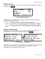
DDC Parameters
Selecting "DDC Parameters" will cause a listbox with a corresponding heading
to appear (see Fig. 42).
Fig. 42. DDC parameters
Regardless of your application and configuration data, this listbox will contain
exactly the following three items:
• "List:" i.e. the list in which the given DDC parameter appears.
• "Number:" the position in the list at which the given DDC parameter appears.
• "Value:" the value of the given DDC parameter; if the value has a unit (e.g.
"sec" or "°C") assigned to it, this unit will be displayed in the upper right-hand
corner.
System Configuration
Selecting "System Configuration" will cause a listbox (consisting of two
screens) with a corresponding heading to appear (see Fig. 43).
Fig. 43. System configuration
Regardless of your application or configuration, this listbox will always contain the
same six items from which to choose. It will thus be necessary to scroll
downwards in order to display all of the items.
31
EN2B-0222GE51 R1101
ALARM DESCRIPTION
EXCEL 50 USER GUIDE
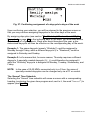
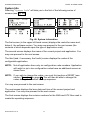
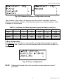
System Info
Selecting "System Info" will take you to the first of the following series of
screens (see Fig. 44).
Fig. 44. System information
The first screen (in the upper left-hand corner) displays the controller name and,
below it, the software version. You may now proceed to the next screen (the
contents of which depends upon the type of application used).
The second screen displays the name of the current project and application. You
may now proceed to the next screen.
The third (and, if necessary, the fourth) screen displays the codes of the
configurable application.
NOTE: Not all application have only six configuration code numbers. Application
with eight or up to ten configuration codes have an additional screen as
shown here.
NOTE: If you wish to change the codes, you must first perform a RESET (see
section "Resetting" on page 3). You will then be able to change the
codes during the resultant start-up sequence.
You may now proceed to the next screen.
The next screen displays the burn date and time of the current project and
application. You may now proceed to the next screen.
The final screen displays the revision numbers for the AMA and ATX files used to
create the operating sequence.
EN2B-0222GE51 R1101
32
EXCEL 50 USER GUIDE
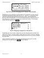
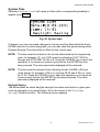
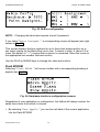
System Time
Selecting "System Time" will cause a listbox with a corresponding heading to
appear (see Fig. 45).
Fig. 45. System time
If desired, you can now make changes to the time and the date which the Excel
50 MMI uses for its control programs; you can also state the period during which
Daylight Savings Time should be in effect for the current year.
NOTE: The date must be entered in the format determined by the engineering
units: for example, 23. July 1997 must be entered as 23.07.1997 for
Europe and 07/23/1997 for the U.S. Press the CANCEL key to abort the
operation or to cancel an incorrect entry before the ENTER key has
been pressed. The value previously displayed will be restored.
NOTE: The time must be entered in the following format: HH:MM in 24-hour
clock format; for example: 9:30 a.m. must be 09:30 and 9:30 p.m. must
be 21:30. Press the CANCEL key to abort the operation or to cancel an
incorrect entry before the ENTER key has been pressed. The value
previously displayed will be restored.
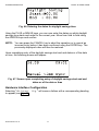
Daylight Saving
The actual dates on which daylight savings time starts and ends in a given year
must be changed on an annual basis. Move the cursor to the "Daylight
Saving" field and confirm. The following screen appears.
33
EN2B-0222GE51 R1101
ALARM DESCRIPTION
EXCEL 50 USER GUIDE
Fig. 46. Entering the dates for daylight savings time
Using the PLUS or MINUS keys, you can now enter the dates on which daylight
savings time starts and ends for the current year. Move from field to field using
the ARROW keys and confirm.
NOTE: You can press the CANCEL key to abort the operation or to cancel an
incorrect entry before it has been confirmed using the ENTER key. The
previously-displayed value will then be restored.
Upon completing entry of the daylight savings start and end dates or of the date
or time, the following screen will appear:
Fig. 47. Screen upon completing entry of daylight savings start and end
dates or of the date or time
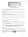
Hardware Interface Configuration
Selecting "HW-Interf. Cfg." will cause a listbox with a corresponding heading
to appear (see Fig. 48).
EN2B-0222GE51 R1101
34
EXCEL 50 USER GUIDE
Fig. 48. Hardware-interface configuration screens
The contents of this listbox will depend upon the specific hardware interfaces
which your controller features. It may be necessary to scroll downwards in order
to display all of the items.
Table 5. Contents of listbox dependent upon hardware interfaces
C-Bus
Lon-Bus
B-Port
Modem
M-bus
XD50-E
/
/
YES
/
/
XD50-F
/
/
YES
YES
/
XD50-FC XD50-FCS XD50-FL
YES
YES
/
/
/
YES
YES
YES
YES
YES
YES
YES
/
YES
/
XD50-FCL
YES
YES
YES
YES
/
C-Bus Configuration
Selecting "C-Bus" will cause a screen with a corresponding heading to appear
(see Fig. 49), and in which you can edit the baud rate and controller number, as
appropriate.
Fig. 49. C-bus configuration
NOTE: Changing the baud rate or the controller number requires a level-3
password.
35
EN2B-0222GE51 R1101
ALARM DESCRIPTION
EXCEL 50 USER GUIDE
NOTE: To provide compatibility with the PC-based XI584 operator and service
software, this C-Bus screen may appear even for controllers with
applications not equipped with a C-Bus connection.
NOTE: If no controller number is set or if the number shown is not reconfirmed,
the controller will not go online on the C-Bus after start-up.
LON-Bus Configuration
Selecting "Lon-Bus" will cause a screen with a corresponding heading to appear
(see Fig. 50), and which displays the unique ID number of the Excel 50 MMI's
Neuron processor.
Fig. 50. LON-bus configuration
B-Port
Selecting "B-Port" will cause a screen with a corresponding heading to appear
(see Fig. 51), and in which you can edit the baud rate, as appropriate.
Fig. 51. B-port configuration
NOTE: Changing the baud rate requires a level-3 password.
Modem
Selecting "Modem" will cause a screen with a corresponding heading to appear
(see Fig. 52).
EN2B-0222GE51 R1101
36
EXCEL 50 USER GUIDE
Fig. 52. Modem configuration
NOTE: Changing the baud rate or the GSM PIN or executing the modem reset
requires a level-3 password.
Baud Rate
If you wish to set the baud rate for the modem/ISDN terminal adapter, select
"Baudrate".
GSM Personal Identification Number (PIN)
If you wish to set the GSM Personal Identification Number (PIN), select "GSM
PIN".
NOTE: The modem baud rate must be set to 9600 for GSM communication to
work.
NOTE: The GSM PIN must be entered right-justified.
Resetting the Modem
If you wish to return modem to factory settings, select "Reset Modem".
NOTE: Resetting the modem will restore the factory defaults and erase any
custom initialization.
NOTE: You must ensure first that the modem is connected. See section
"Remote Communications" of the Excel 50 Controller Installation
Instructions, EN1B-101, for more information.
M-Bus
NOTE: The entry "M-Bus" will appear only if your Excel 50 controller has been
equipped with M-bus modules (FCS).
Selecting "M-Bus" ("M" = "meter bus") will cause a screen with a corresponding
heading to appear (see left screen in Fig. 53) in which you can change the baud
rate, if desired.
37
EN2B-0222GE51 R1101
ALARM DESCRIPTION
EXCEL 50 USER GUIDE
Fig. 53. M-Bus configuration
NOTE: Changing the baud rate requires a level-3 password.
If you select "Point Assignmt.", a corresponding screen will appear (see right
screen in Fig. 53).
This screen displays the bus numbers for up to three heat meters and/or up to
two water meters on the Meter Bus (up to max. 3 meters in total). A value of 0 or
lower (the default is "-1") means that no device is connected. Move the cursor to
the appropriate bus number field and confirm.
Use the PLUS or MINUS keys to change the value and confirm.
Flash EPROM
Selecting "Flash EPROM." will cause a listbox with a corresponding heading to
appear (see Fig. 54).
Fig. 54. Hardware-interface configuration screens
Regardless of your application or configuration, this listbox will always contain the
same three items from which to choose.
• By selecting "Save Applic." you can burn all data of the current application
into the Flash EPROM.
EN2B-0222GE51 R1101
38
EXCEL 50 USER GUIDE
• By selecting "Erase Flash", you can erase all data from the Flash EPROM.
• By selecting "Show Applic.", you can display saved applications and their
respective burn dates.
Saving the Application
If "Save Applic." is selected, the following screen will appear (see Fig. 55).
Fig. 55. Burning Flash
If, however, the Flash memory is full, a screen with a corresponding message
(and also displaying the date and clock-time) will appear (see Fig. 56).
Fig. 56. Flash memory full
Erasing the Flash Memory
If "Erase Flash" is selected, the following screen will appear (see Fig. 57).
39
EN2B-0222GE51 R1101
ALARM DESCRIPTION
EXCEL 50 USER GUIDE
Fig. 57. Erasing the flash memory
Showing the Application
If "Show Applic." is selected, the following screen will appear (see Fig. 58).
Fig. 58. Showing the application
Bus-Wide Access
The "Bus-wide Access" function uses the MMI of this controller to display or to
make changes to other EXCEL 50 controllers without MMI which are connected to
the same C-bus.
Selecting "Buswide Access" will cause a screen with a corresponding heading
to appear (see Fig. 59).
Fig. 59. Bus-wide access
Regardless of your application or configuration, this screen will always contain the
same four entries.
EN2B-0222GE51 R1101
40
EXCEL 50 USER GUIDE
Move the cursor to
• "Login" in order to log in to another controller on the same C-bus.
• "Logoff" in order to log off from the remote controller to which you are logged
in at the moment (appears only when accessing a slave controller from a
remote controller).
• "On" to enable the logging of alarms coming from other controllers on the bus
(these alarms can then be displayed after pressing the ALARMS fast-access
key while in the "Bus-wide Alarms" menu).
• "Off" to disable the logging of alarms coming from other controllers on the
bus.
and confirm.
Remote Login
If you select "Login", a screen resembling Fig. 60 will appear.
Fig. 60. Remote login
Depending upon the number of different controllers registered in your network (on
the C-bus), the resultant listbox will contain the names of a variable number of
controllers.
Move the cursor to the controller you want to log into and confirm.
NOTE: From now on, all visible screens are the screens of the remote controller.
The first screen of the remote controller will be the start screen. You can
now access all screens of the remote controller. Use the "Bus-wide
Access" function via the SYSTEM TOPICS fast-access key to return to
the screens of your own controller. Use the LOGOFF function or select
your own controller in the controller list of the LOGIN function. If you do
not press a key for 10 min, you will also be logged off. You will return to
the controller list screen of the LOGIN function on your own controller.
Logging in to a controller that uses an XI581AH/582AH operator interface
41
EN2B-0222GE51 R1101
ALARM DESCRIPTION
EXCEL 50 USER GUIDE
results in only part of the information from that controller being displayed
on the Excel 50 screen (due to its smaller screen size).
Remote Logoff
If "Logoff" is selected, you will be logged off from the remote controller and
return to the controller list screen of the LOGIN function on your own controller.
Remote Alarms On/Off
If "On" or "Off" has been selected, alarms from remote controllers will be
displayed or suppressed. The screen will remain the same and no changes are
visible.
DDC Times
Move the cursor to the "DDC Times" item and confirm.
Fig. 61. DDC times
This screen displays the execution time and RACL cycle time in seconds. The
cycle time can be changed to optimize the system performance.
NOTE: Changing the cycle time requires a level-3 password. Move the cursor to
the "Cycl. Time" field and confirm.
EN2B-0222GE51 R1101
42
EXCEL 50 USER GUIDE
THE ALARMS FAST-ACCESS KEY
Fig. 62. The ALARMS fast-access key
Pressing the ALARMS fast-access key displays the main alarm menu screen to
enable selection of the following:
•
•
•
•
alarm buffer
points in alarm
critical alarms
non-critical alarms.
Alarm Buffer
The last 99 alarms are stored in the alarm buffer. Typical alarm information
includes:
• Date and time the alarm occurred
• Name of the data-point in alarm
• Value/state of the data-point in alarm
• Alarm text, e.g. MIN1 alarm.
When the alarm memory capacity is exceeded, the first alarm is overwritten.
Alarms are organized on a first in, first out basis. The contents of the alarm buffer
can be displayed on the Excel 50 MMI.
43
EN2B-0222GE51 R1101
ALARM DESCRIPTION
EXCEL 50 USER GUIDE
Point in Alarm
All data-points currently in an alarm condition, i.e. the alarm limit for an analog
point or the alarm state for a digital point has been reached, can be displayed on
the Excel 50 MMI. When selecting this option, the data-point's name and
associated alarm text will be displayed.
Critical / Non-Critical Alarms
The following attributes can generate alarms and will write them into the alarm
buffer as well as sending them to the PC central via the C-Bus.
Alarm Attributes
With the "Min Limit", "Max Limit", "Totalizer", and "Alarm State" attributes, you can
classify alarms as either critical or non-critical.
NOTE: The "Operating Mode" attribute always generates a critical alarm.
System Alarms Description
Operating malfunctions arising within a controller (e.g. power failure) or during
communication with another Excel 5000 device are displayed on the Excel 50
MMI.
NOTE: System alarms are always critical alarms.
Min. / Max. Limit Monitoring
Two maximum limits ("Max Lim1" and "Max Lim2") and two minimum limits
("Min Lim1" and "Min Lim2") can be independently set for physical and pseudo
analog inputs.
The limit values can be changed using the operator sequence. Each time a limit
value is reached, irrespective of direction, an alarm is generated.
EN2B-0222GE51 R1101
44
EXCEL 50 USER GUIDE
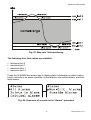
Fig. 63. Max./min. limit monitoring
The following four limit values are available:
•
•
•
•
minimum limit 2
minimum limit 1
maximum limit 1
maximum limit 2
Press the ALARMS fast-access key to display alarm information on alarm history,
points currently in an alarm condition, critical alarms, non-critical alarms, and buswide alarms.
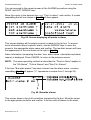
Fig. 64. Sequence of screens in the "alarms" procedure
45
EN2B-0222GE51 R1101
ALARM DESCRIPTION
EXCEL 50 USER GUIDE
You can proceed to the second screen of the ALARMS procedure using the
RIGHT and LEFT ARROW keys.
Move the cursor to the desired item, e.g. "Point in alarm", and confirm. A screen
resembling the left one shown in Fig. 65 will then appear.
Fig. 65. Screen displaying all points in alarm
This screen displays all the points currently in alarm in the list box. To access
more information about a specific alarm, use the ARROW keys to move the
cursor to the appropriate alarm name and confirm. The resultant screen will have
the appearance of the one shown to the right in Fig. 65.
Alarm information (comprising the date, time, alarm name, value/state and alarm
reason) is displayed. Press CANCEL to return to the previous screen.
NOTE: The same operating method as described for "Point in Alarm" applies to
the "All Alarms", "Critical Alarms" and "Non-Crit. Alarms".
If the item "Bus-wide alarms" has been chosen from the alarm menu, a screen
resembling Fig. 66 will appear ("#" represents a number from 1 through 30).
Fig. 66. Buswide alarms
This screen shows a list of all controllers connected to the bus. Move the cursor
to the appropriate controller and confirm. A list box with all alarms in the alarm
EN2B-0222GE51 R1101
46
EXCEL 50 USER GUIDE
buffer of the specified controller will be displayed in a screen resembling the left
screen shown in Fig. 65. Move to the appropriate alarm and confirm.
47
EN2B-0222GE51 R1101
ALARM DESCRIPTION
EXCEL 50 USER GUIDE
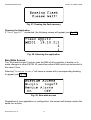
POWERING UP / RESETTING THE CONTROLLER
After powering up the controller or following a RESET (see section "Resetting"
"Basic Function Keys" on page 3), the following series of screens (the so-called
"start-up sequence") appears (see Fig. 67).
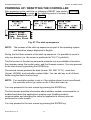
Fig. 67. The start-up sequence
NOTE: The screens of the start-up sequence are part of the operating system
and therefore always displayed in English.
During the first three screens of the start-up sequence, it is possible to move in
only one direction (i.e. the cursor is positioned at "NEXT" by default).
The first screen of the start-up sequence presents only non-editable information:
the company name, the model name, and the firmware version. You may proceed
to the next screen by pressing the ENTER key.
The second screen presents the date (format: DD. MM. YYYY), clock-time
(format: HH:MM), and controller number fields. You can edit any or all of these
fields using the basic function keys
NOTE: If no controller number is set or if the number shown is not reconfirmed,
the controller will not go online on the C-Bus after start-up.
You may proceed to the next screen by pressing the ENTER key.
The third screen provides information about whether modem communication is
enabled and about the application's memory size. Enabling modem
communication and changing the value for application's memory size are
performed in a later screen.
You may proceed to the next screen by pressing the ENTER key.
EN2B-0222GE51 R1101
48
EXCEL 50 USER GUIDE
The fourth screen contains editable fields for configuring the controller-specific
hardware interfaces ("Contr. Setup"), choosing the application manually
("Select Applic."), downloading an application from either the PC-based
XI584 operator and service software or from the XBS Central A ("Requ.
Download"), and setting up the test mode with default data-point names ("DP
Wiring Check"). Move your cursor to the desired entry and confirm by pressing
the ENTER key. Depending upon your selection, you will proceed to one of the
series of screens described in the respective section below.
Hardware Interface Configuration
Selecting and confirming "Contr. Setup" will cause a listbox headed "HWInterf. Cfg." to appear (see Fig. 68).
49
EN2B-0222GE51 R1101
ALARM DESCRIPTION
EXCEL 50 USER GUIDE
Fig. 68. Hardware interface configuration
To view/configure the fourth entry ("Modem"), you will have to scroll downwards.
See also section "Hardware Interface Configuration" on page 34.
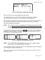
Choosing an Application Manually
Selecting and confirming "Select Applic." will cause a listbox headed
"Choose Applic." to appear (see Fig. 69).
EN2B-0222GE51 R1101
50
EXCEL 50 USER GUIDE
Fig. 69. Choosing an application manually
Move the cursor to the desired application and confirm.
The initialization screen of the chosen application will appear. It displays
information about the versions of the controller and the application.
Bus numbers are appended automatically, except in the case of remote points. In
the case of remote points, the remote controller number must be entered in
through the data-points sequence.
NOTE: The controller's number is appended to the data-point's name (see also
section "Appending the Controller's Number to the Data-Points' Names")
in order to identify the controller to which the it belongs.
In the following sequence of screens (see Fig. 70), the codes of the configurable
application can be changed. The application codes can be generated with the
"LIZARD-Excel 50 Application Selector".
Fig. 70. Sequence of configuration screen
NOTE: If the "LIZARD-Excel 50 Application Selector" is not available, please
contact your local Honeywell branch for support.
In the appropriate screen, move the cursor to the appropriate code and change its
value using the PLUS and MINUS keys.
When you are finished, go to the third screen, move the cursor to the "CONFIG"
field, and confirm.
51
EN2B-0222GE51 R1101
ALARM DESCRIPTION
EXCEL 50 USER GUIDE
If the codes entered in the screens are allowed, the default screen of normal
operation will appear:
If one or more codes entered are not allowed, the initialization screen will appear
again. Change the screens by using the LEFT and RIGHT ARROW keys until you
have returned to the configuration screen. Codes which are not allowed have the
value "-1" instead of the previously entered code. Change the codes until all
codes are correct.
You will now come to the default screen of normal operation (see Fig. 4 on page
5).
Downloading an Application
After resetting (see section "Resetting" on page 3), the start-up sequence will
appear (see Fig. 67), in the fourth screen of which you can request a download
("Requ. Download"), after which the following screen will appear (see Fig. 71).
Fig. 71. Downloading an application
You may then proceed as follows
1. Establish the physical connection (e.g. a null-modem cable) between the XL50
B-Port and your PC.
2. Launch lizard.exe on your PC.
3. Open one of the applications (e.g. HE01V2.00 (XD50 F, FC, FL, FCL & FCS)
present in the corresponding sub-folder. A list of equipment units (not to be
confused with "Plant Components") will then appear.
4. Select the desired configuration (i.e. assemblage of equipment units).
5. Under "Options", check the COM port and baud rate. The selected baud rate
must agree with the baud rate setting of the XL50 MMI. For verification
purposes, the configuration parameters will then be again displayed.
EN2B-0222GE51 R1101
52
EXCEL 50 USER GUIDE
6. In the XL50 MMI LCD display, a screen (see Fig. 4 on page 5) stating the date
and clocktime will appear. You have now completed the downloading
procedure.
NOTE: The fastest download is achieved by setting both the XL50 B-Port and
the Lizard PC-COMPORT baud rates to 38400 baud.
Setting Up the Test Mode with Default Data-Point Names
Selecting and confirming "DP Wiring Check" will cause the following screen to
appear (see Fig. 72).
Fig. 72. Setting up the test mode with default data-point names
The resultant default data-point's names are generated according to the following
pattern:
AI0101:
AO0201:
DI0301:
DO0401:
Analog input, board 1, input 1
Analog output, board 2, output 1
Digital input, board 3, input 1
Digital output, board 4, output 1
NOTE: The board numbers shown above are internal references and are not
relevant to the User. In Excel 50 Controllers, the numbers are fixed for
the I/O type, i.e. analog inputs are always AI01, digital inputs are always
DI03, etc.
After generating the default data-point's names, the alarm displayed in Fig. 72 first
needs to be cancelled. This is done, the following screen will appear:
53
EN2B-0222GE51 R1101
ALARM DESCRIPTION
EXCEL 50 USER GUIDE
Fig. 73 Canceling the alarm
Move the cursor to
• "Default Points" to display I/O points for checking values and manually setting
outputs for testing.
• "Alarm History" to display current alarms. This feature allows the system to be
checked out by a single person opening and closing inputs and then later
reading the alarm buffer to see if they were detected by the controller.
and confirm using the ENTER key.
If "Default Points" has been selected, a listbox similar to Fig. 74 will be
displayed showing all default data-point names and their current values.
Fig. 74. Default data-point names
To manually set the state/value of output data-points, use the ARROW keys to
move the cursor to the appropriate output data-point from the list box and confirm.
In the case of e.g. analog output data-points, a screen similar to Fig. 75 will be
displayed.
EN2B-0222GE51 R1101
54
EXCEL 50 USER GUIDE
Fig. 75. Manually setting the state/value of analog output data-points
Confirm the displayed value with ENTER, or change the value using the PLUS or
MINUS keys and confirm. In the case of e.g. digital output data-points, a screen
similar to Fig. 76 will be displayed.
Fig. 76. Manually setting the state/value of digital output data-points
Confirm the displayed value with ENTER, or change the state/value using the
PLUS or MINUS keys and confirm.
If "Alarm History" has been selected, a listbox similar to the one shown in Fig. 77
will be displayed showing all points in alarm as well as any system alarms (max.
100 entries):
Fig. 77. Alarm history
55
EN2B-0222GE51 R1101
ALARM DESCRIPTION
EXCEL 50 USER GUIDE
NOTE: Alarms are generated for changes of state/value on inputs, which allows
shorting and opening the inputs at the switches and/or sensors and then
checking the alarm buffer to verify the wiring.
To display an alarm, use the ARROW keys to move the cursor to the default datapoint's name from the list box and confirm. A screen similar to Fig. 78 will appear.
Fig. 78. Displaying an alarm
If, by manipulating the hardware, you change the state to "1", "return to normal"
will be displayed.
NOTE: Reset the controller after using the test options to clear the alarm buffer.
EN2B-0222GE51 R1101
56
EXCEL 50 USER GUIDE
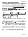
APPENDIX 1: DATA-POINT ATTRIBUTES
The information pertaining to a particular data-point is referred to as its attributes.
In the following sections, the data-points available on the Excel 50 MMI are
presented. Depending upon the data-point's type (analog input, digital output,
etc.), it can have various different attributes. The meanings of these attributes are
explained most extensively in section "Analog Input Data-Point Attributes".
Analog Input Data-Point Attributes
See also section "Types of Physical Data-Points" on page 25 for a description of
analog input data-points. Their editable and non-editable attributes are displayed
in the following series of screens:
Fig. 79. Analog input data-point attributes (as exemplified by OATemp)
In the first screen, the data-point's name (which is non-editable) is displayed. You
can edit the switch-point value/state (the engineering unit is non-editable) and/or
change the operating mode field from "AUTO" to "MANUAL" (and vice-versa). See
also section "The 'Operating Mode' Attribute".
NOTE: If the operating mode is changed, an alarm screen with the message
"Manual operation" or "Auto operation" appears. Confirm the
alarm with CANCEL. You may now proceed to the next screen.
In the second screen, you can enable/disable trend logging for this data-point by
changing the attribute "Trend Log" from "ON" to "OFF" (and vice-versa). You can
also edit the values for "Cycle" and/or "Hyster".
NOTE: If "Cycle" is set to anything other than 0, time-based trending is
enabled. If "Cycle" is set to 0, then value-hysteresis trending is enabled
using the absolute value specified for "Hyster".
57
EN2B-0222GE51 R1101
ALARM DESCRIPTION
EXCEL 50 USER GUIDE
In the third screen, the data-point's "Sup.Alarm" (suppress alarm) attribute can
be changed from "YES" to "NO" and vice-versa. The "Sup.Alarm" attribute allows
the user to choose which point alarm will be generated and which one not. If the
"Sup.Alarm" attribute is set to "YES", no alarm will be generated, even if the
alarm condition of this data-point occurs.
In the third screen, you can also edit the value of the "Min Lim2" and/or "Min
Lim1" attributes. See also section "Min. / Max. Limit Monitoring" on page 44.
In the fourth screen, you can edit the values of the "Max Lim1", "Max Lim2", and
"S.Offset" (sensor offset) attributes. See also section "Min. / Max. Limit
Monitoring" on page 44.
The fifth screen displays the data-point's technical address (which is noneditable). The technical address is a six-digit number. The first two digits stand for
the controller number. The next two digits stand for the board number. The last
two digits stand for the physical point address.
Analog Output Data-Point Attributes
See also section "Types of Physical Data-Points" on page 25 for a description of
analog output data-points. Their editable and non-editable attributes are displayed
in the following series of screens:
Fig. 80. Analog output data-point attributes (as exemplified by PumpRotSp)
"time to open" / "time to close": This attribute pertains only to analog
output data-points and shows - for example - the time an actuator needs to open
and close a valve.
See also the previous section for information on previously-described attributes.
EN2B-0222GE51 R1101
58
EXCEL 50 USER GUIDE
Digital Input Data-Point Attributes
See also section "Types of Physical Data-Points" on page 25 for a description of
digital input data-points. Their editable and non-editable attributes are displayed
in the following series of screens:
Fig. 81. Digital input data-point attributes (as exemplified by HG1_PmpState)
The "AlmReport" (alarm reporting) attribute: Setting this attribute to "YES" will
cause the state of the digital input data-point to be checked for a change; in the
event of a change, an alarm is generated.
The "AlmDelay" (alarm delay) attribute: Using this attribute, the delay (in
seconds) until an alarm is generated can be set.
"hours run" enable/disables measuring of the runtime of the connected actuator
(e.g. a pump).
hours run (not editable)
See also the previous sections for information on previously-described attributes.
Digital Output Data-Point Attributes
See also section "Types of Physical Data-Points" on page 25 for a description of
digital output data-points. Their editable and non-editable attributes are displayed
in the following series of screens:
59
EN2B-0222GE51 R1101
ALARM DESCRIPTION
EXCEL 50 USER GUIDE
Fig. 82. Digital output data-point attributes (as exemplified by HG1_PmpCmd)
See also the previous sections for information on previously-described attributes.
Pseudo Analog Data-Point Attributes
See also section "Types of Pseudo Data-Points" on page 26 for a description of
pseudo analog data-points. Their editable and non-editable attributes are
displayed in the following series of screens:
Fig. 83. Pseudo analog output data-point attributes (as exemplified by
CPU_Calc_Htg_Sp)
Pseudo Digital Data-Point Attributes
See also section "Types of Pseudo Data-Points" on page 26 for a description of
pseudo digital data-points. Their editable and non-editable attributes are
displayed in the following series of screens:
Fig. 84. Pseudo digital data-point attributes (as exemplified by
EXECUTING_STOP)
EN2B-0222GE51 R1101
60
EXCEL 50 USER GUIDE
See also the previous sections for information on previously-described attributes.
Remote Analog Data-Point Attributes
See also section "Types of Remote Data-Points" on page 26 for a description of
remote analog data-points. Their editable and non-editable attributes are
displayed in the following series of screens:
Fig. 85. Remote analog data-point attributes (as exemplified by
CPU_Calc_Htg_Sp)
The second screen shows the controller number of the remote point. Remote
points always receive their values from pseudo-analog points originating in source
controllers. The remote point and pseudo-analog point must have the same
name. During the start-up sequence, this controller number must be set to the
value of the source controller's number; otherwise, no communication will occur.
The "Broadcast Hyst." (broadcast hysteresis) attribute is similar to a trend
hysteresis. The value is broadcast if the given hysteresis (absolute value) is
exceeded.
See also the previous sections for information on previously-described attributes.
Remote Digital Data-Point Attributes
See also section "Types of Remote Data-Points" on page 26 for a description of
remote digital data-points. Their editable and non-editable attributes are displayed
in the following series of screens:
61
EN2B-0222GE51 R1101
ALARM DESCRIPTION
EXCEL 50 USER GUIDE
Fig. 86. Remote digital data-point attributes (as exemplified by
CPU_Calc_Htg_Sp)
Totalizer Data-Point Attributes
See also section "Types of Physical Data-Points" on page 25 for a description of
totalizer data-points. Their editable and non-editable attributes are displayed in
the following series of screens.
If set to "MANUAL", totalizer points will be automatically set back to the "AUTO"
mode insofar as accurate pulse counting would not otherwise be possible.
Fig. 87. Totalizer data-point attributes (as exemplified by Heat_Meter1)
See also the previous sections for information on previously-described attributes.
M-Bus Data-Point Attributes
An additional basic group of data-points called "M-bus points" will appear only if
your Excel 50 MMI has been equipped for M-bus modules (FCS).
See also Lizard documentation for a description of M-bus data-points. Their
editable and non-editable attributes are displayed in the following series of
screens:
Fig. 88. M-bus data-point attributes (as exemplified by CV1_Energy)
EN2B-0222GE51 R1101
62
EXCEL 50 USER GUIDE
Individual Data-Point Attributes
Data-Point Name
The data-point's name is just one of its attributes.
The name of each data-point (physical and pseudo) can be displayed on the
Excel 50 MMI. However, access to change physical and pseudo data-points
depends on the operator's access level.
Appending the Controller's Number to the Data-Points' Names
Remote data-points (also known as global data-points) are data-points used by
more than one controller operating on the same C-bus.
When more than one controller with the same application program exists on the
C-bus, the controller's number must be appended to the data-point's name. This
must be done in order to make it unique (likewise, the controller's number must
also be appended to the controller's name in order to make it unique).
Bus numbers are appended automatically, except in the case of remote points. In
the case of remote points, the remote controller number must be entered in
through the data-points sequence.
The controller's number will then be automatically appended to the names of all
data-points.
NOTE: The controller number is displayed only on the PC central and not on the
Excel 50 MMI.
The 'Operating Mode' Attribute
The "Operating Mode" attribute is an attribute of some data-points. This attribute
enables the user to switch between the manual and automatic operation modes.
Each change from the automatic operation mode to manual operation mode and
back again generates a critical alarm.
Automatic Operation Mode: In the case of automatic operation, the Excel 50
MMI normally processes the values received from the inputs, e.g. from
temperature sensors, while the state of outputs normally shown by the user / time
program is adopted, e.g. "Heating circuit pump off". The feedback loop of the
control system is closed. When the controller is in the automatic operation mode,
the value or the current state being processed by the application program is
contained in the "value" attribute. In the case of an analog input, for example, the
63
EN2B-0222GE51 R1101
ALARM DESCRIPTION
EXCEL 50 USER GUIDE
"value" attribute is the current room temperature. In the case of a pump switched
by the digital output, for example, the "value" attribute is the current state (e.g.
"ON").
Manual Operation Mode: During manual operation, the controller uses the
manual values, e. g. "Flow temperature set-point = 60 °C". Outputs adopt the
preselected condition, e. g. "Heating circuit pump on". The feedback loop of the
control system is interrupted. When the controller is in the manual operation
mode, the data specified manually is written into the "manual value" attribute,
processed in the controller, and passed on to an output. The user can, of course,
recall the measured value coming from the "value" attribute, but this has no effect
on the application.
Optimizing a Switch-Point
The optimization function is used to optimize a switch-point. It has two states:
"ON" and "OFF".
Optimization compensates the time an environment needs to reach a desired
condition (temperature, humidity, etc.) by advancing the switch-point of the
corresponding device / actuator so that it starts at an earlier time.
NOTE: The optimization can be set to "ON" only if the given data-point is suitable
for optimization.
Example: If the optimization is set to "ON", a heating plant is switched on early so
that a particular room will be at the required switch-point level by a particular time.
Programmed switch-point:
6:00 to 20 °C
Real switch-point:
4:52 to heating ON
The difference between the programmed and the real switch-point is the
estimated time a room needs to warm up under the current conditions.
EN2B-0222GE51 R1101
64
EXCEL 50 USER GUIDE
Home and Building Control
Honeywell Inc.
Honeywell Plaza
P.O. Box 524
Minneapolis, MN 55408-0524
USA
http://www.honeywell.com
EN2B-0222GE51 R1101
Home and Building Control
Honeywell Limited-Honeywell Limitee
155 Gordon Baker Road
North York, Ontario
M2H 3N7
Canada
http://www.honeywell.ca
Home and Building Control
Honeywell AG
Böblinger Straβe 17
D-71101 Schönaich
Germany
http://europe.hbc.honeywell.com
printed in Germany
Subject to change without notice