1
Profile generator
for tumblers, mixers
and kneaders
B 70.0107
Operating Instructions
9.00/00387068
Contents
1.1 Profile program entry ............................................................................................. 3
1.1.1 Entering setpoints and operating contacts .............................................................. 3
1.2 Automatic operation .............................................................................................. 4
1.2.1 Starting and cancelling the profile program ............................................................. 4
1.2.2 Profile program sequence ........................................................................................ 5
1.3 Manual operation ................................................................................................... 6
1.3.1 Starting and cancelling manual operation ............................................................... 6
1.4
Special functions .................................................................................................... 6
1.5
Cd functions ........................................................................................................... 7
1.6
Relay assignment table ......................................................................................... 8
1.7 Profile program transmission via the service channel ....................................... 9
1.7.1 Telegram structure .................................................................................................... 9
1.7.2 Structuring the user data for transmission of profile program ............................... 10
1.8
Connection diagram ............................................................................................ 11
9.00/LPT-100
Operation
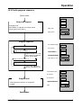
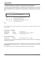
1.1 Profile program entry
1.1.1 Entering setpoints and operating contacts
The program entry is always initiated with the “Pgm” key, which is also used to terminate it. A blinking display requests you to enter a value or a switching state. The “ENTER” key is used to acknowledge each entry. The program entry can be locked through an external input (default setting:
logic input 2).
Basic
status
Grundstellung
Pgm
Enter
program eingeben
No.
Programm-Nr.
number
keys 0..9
0–9
-Zifferntasten
n o
0 0
ENTER
Enter
phase eingeben
No.
0 0 : 0 0
Phasen-Nr.
number keys 0 – 9
YES = Programm
program available
YES
vorhanden
no ==Programm
program not
no
nicht
available
vorhanden
Err
=
program faulty,
Err = Programm
fehlerhaft,
must
be Cd
deleted
muß mit
2
with
Cd 2werden.
gelöscht
Phase time
Phasenzeit
0
Zifferntasten 0.. 9
ENTER
Enter
phaseeingeben
time
Phasenzeit
number
keys 00..
– 99
Zifferntasten
Min/Sek
0 0 : 0 0
ENTER
Enter
section No.
Abschnitt-Nr.
eingeben
number
keys 00..
– 99
Zifferntasten
0
LED off:
LED
aus:hh:mm
hh:mm
LED on:
LED
an: min:sec
min:sec
Displayed
are:
Angezeigt wird:
Setpoint
for
Sollwert der
circulation
rate,
Umdrehungsgeschwindigkeit,
section
run-time, program
No.,
Abschnitt-Laufzeit,
Programmphase
No.
Nr, Phasen-Nr.
ENTER
Setpoint
rate
Sollwert circulation
Umwälzgeschw.
number
keys 00..
– 99
Zifferntasten
Min/
Sek
0 0 0
ENTER
Min/Sek
Enter
section time
Abschnittzeit
eingeben
number
keys 0 0..
– 99
Zifferntasten
0 0 : 0 0
ENTER
out
Set
operating contacts
Steuerkontakte
setzen
keys
out1
– out12
Tasten
out1..
out12
LED
LEDoff:
aus:hh:mm
hh:mm
LED
LEDon:
an: min:sec
min:sec
The mit
section
will only be
Erst
der Eingabe
valid
after
entering
the
einer Abschnittszeit wird
section
time.
der Abschnitt gültig.
LED
LED blinks:
blinkt: not
nichtset
gesetzt
LED
LED on:
an: set
gesetzt
ENTER
Pgm
Basic
status
Grundstellung
9.00/LPT-100
5
Operation
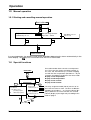
1.2 Automatic operation
1.2.1 Starting and cancelling the profile program
Basic
status
Grundstellung
Enter
program eingeben
No.
Programm-Nr.
number
keys 0..9
0–9
-Zifferntasten
Schnellstart
quick
start oroder
externerstart
Start
external
n o
0 0
ENTER
Enter
phase
No.
Phase-Nr.
eingeben
number keys 0 – 9
Zifferntasten 0.. 9
YES == Programm
program available
YES
vorhanden
no ==Programm
program not
no
nicht
available
vorhanden
Err == Programm
program faulty
Err
fehlerhaft
0
ENTER
Min/Sek
Enter delayeingeben
time
Vorlaufzeit
0 0 : 0 0
number keys 0 – 9
Zifferntasten
0.. 9
ENTER
Automatic
program
Automatischer
sequence
Programmablauf
-
boiler temperature process value
-
boiler vacuum process value
-
circulation rate setpoint
-
residual program run-time
-
program No.
-
phase No.
-
section No.
-
energized operating contacts: illuminated diodes
in the number keys indicate that the output is
activated.
When über
configured
via27the
Wenn
Cd-Code
Cd code 27, erfolgt
the USER/
konfiguriert,
an dieser
BATCH
entered
Stelle dienumber
Eingabeisder
here.
USER-/CHARGEN-Nummer.
The
Das program
Programmswitches
schaltet off
nach
automatically
after the end
Ablauf der Programmlaufzeit
of
the program
automatisch
ab. run-time.
Basic
status
Grundstellung
Display in automatic operation
LED off:
LED
aus:hh:mm
hh:mm
LED
LED on:
an: min:sec
min:sec
Temporary alterations
alter circulation speed
alter residual phase time
alter operating contacts
total section run-time
(cannot be altered)
The “Hand” key is used to pause the profile program sequence at any time. The LED in the “Hand”
key lights up.
The profile program sequence can also be paused externally, via a logic input. In this operating status, the LED in the “Hand” key will blink.
v The
key will stop the program at any time.
v The program can also be cancelled via a logic input (default setting: logic input 4)
In automatic operation and in the basic status, the process value of the revolutions determined can
be indicated in the lower display (the LED in the key is illumimated), by using the
key.
6
9.00/LPT-100
Operation
1.2.2 Profile program sequence
Basic
status
Grundstellung
Delay time elapsed
Ablauf Vorlaufzeit
falls
programmiert
if programmed
forced
delay, if required,
to maintain motor
ggf.
Zwangsvorlauf,
um Motorvorwarnzeit
warning alarm time (Cd 11)
(Cd 11) einhalten zu können
Delay time
Vorlaufzeit
01:30
Pgm,
Pgm,phase
Phase
05
PV
temp.
IWchamber
Kammertemp.
54.6
PV
IWvacuum
Vacuum
1. 2 3
SP
SWrevolution
Umdrehung
088
Resid.
program time
Programmrestzeit
12:34
Pgm,
Pgm,phase,
Phase,sect.
Abs
05
0
Program sequence
Programmablauf
Prog.
0,0,
Sect.
Prog.5,5,Phase
Phase
Abs.0 0
Prog.
Prog.5,5,Phase
Phase0,0,Sect.
Abs.nn
Repeat
ofAbs.
Sect.
Wdh. von
0-n0-n, until
bis Phasenzeit
abgelaufen
phase
time has
elapsed,
oder
ext.
Phasenvorlauf
or
ext.
phase
delay
Prog.
5, 5,
Phase
1, Sect.
0 0
Prog.
Phase
1, Abs.
1 0
Prog.
Prog.5,5,Phase
Phase1,1,Sect.
Abs.nn
Processing
additional
Abarbeitung weiterer
phases,
if programmed
Phasen, falls
programmiert
Program end
Programmende
End
of der
program
end-time, if falls
configured
Ablauf
Programmendezeit,
konfiguriert
(Cd 08)
(Cd 08)
PV
temp.
IWchamber
Kammertemp.
54.6
PV
IWvacuum
Vacuum
1. 2 3
SPSW
revolution
Umdrehung
000
Program
end-time
Programmendezeit
00:59
Pgm
Pgm
05
Basic
status
Grundstellung
9.00/LPT-100
7
Operation
1.3 Manual operation
1.3.1 Starting and cancelling manual operation
Basic status
Grundstellung
out
Setpoint
rate
Sollwert circulation
Umwälzgeschw.
0 0 0
number
keys
0
–
9
Zifferntasten 0.. 9
Set
operating contacts
Steuerkontakte
setzen
keys
out1
–
out12
Tasten out1.. out12
ENTER
LED blinks:
not set
LED
blinkt: nicht
gesetzt
LED on:
set
LED
an: gesetzt
ENTER
Basic
status
Grundstellung
In manual operation, the process value of the revolutions determined is shown automatically in the
lower display. The
key has no function here, the LED is illuminated.
1.4 Special functions
Basic
status
Grundstellung
Pgm
Password
entry
Passworteingabe
2345
9510
Zu
löschende
Programmnummer
Enter
program
number
eingeben:
to be deleted:
0 -–19:
19:entsprechendes
delete corres-Programm
löschen
ponding program
20
Programme
löschen
20: : alle
delete
all programs
Enter
code
Code eingeben
-Zifferntasten
0..90 – 9 C d 0 3
number
keys
ENTER
Enter
parameter
Parameter
eingeben
number
keys0..
0 –9 9
Zifferntasten
One code number often conceals several parameters. These are then shown one below another. In
this case, too, the ENTER key is used for stepping
on. With the limit comparators (Cd code 34 – 36), for
example, the following assignment has to be made:
Display 1: LK1 temperature
Display 2: LK2 temperature
Display 3: LK1 vacuum
Display 4: LK2 vacuum
The relay assignment table (Cd 50) consists of 30
lines with two columns each. The lines are differentiated by the numbers 1 – 30. The first column (display 1) indicates the source function, the second
column (display 2) the target relay according to the
table on page 8.
ENTER
ENTER
Pgm
Basic
status
Grundstellung
8
9.00/LPT-100
Operation
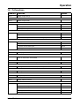
1.5 Cd functions
Code No. Function
Cd-03
display range start (2)
Cd-04
display range end (2)
Cd-05
mode of circulation rate
0 = entry in 0 – 100 % for 0 – 10 V
Default
default
1 = entry in 0 – x rpm
Cd-06
max. value of circulation rate
default 999
in rpm
max. value corresponds to 10 V at the analog output
Cd-07
display process value revolutions
0 = no function
1 = pulses at the count input
default
2 = integral for the speed value
Cd-08
profile program end-time 0 – 255 sec
Cd-09
accept factory default setting
enter 15 and confirm with ENTER
Cd-10
switch-off time of oper. function prior to section change 0 – 300 sec
default 5
Cd-11
warning alarm time for motor run ( min : sec ) 00:00 not active
default 0
Cd-12
warning duration 0 – 255 sec
default 0
Cd 17
display temperature at the terminals
Cd-25
display software version
Cd-27
batch and user number
0 = no number entry
default 60
default
1 = entry of batch number
2 = entry of user number
3 = entry of batch and user number
9.00/LPT-100
9
Operation
Cd 33
comparative values for limit comparators
0 = no function (limit comparator not activated)
1 = process value for temperature
2 = process value for vacuum
3 = process value for count input
Cd-34
4 LK functions
0 = comparator (lk 7)
default
2 = inverse comparator (lk 8)
Cd-35
4 LK limit values ( -19.9 to 99.9 °C )
default 0
Cd-36
4 LK differentials ( 00.0 to 09.9 )
default 0
Cd-45
display and keypad test: enter value 1 and confirm, cancel with PGM +
ENTER
Cd-50
table of assignment for logic outputs -> relays
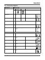
1.6 Relay assignment table
(S)ource number
1
2
3
4
5
6
7
8
9
10
11
12
13
14
15
16
17
18
19
20
10
Meaning
operating function 1
operating function 2
operating function 3
operating function 4
operating function 5
operating function 6
operating function 7
operating function 8
operating function 9
operating function 10
operating function 11
operating function 12
combination alarm
LK temperature 1
LK temperature 2
LK vacuum 1
LK vacuum 2
preliminary contact, motor
profile program end signal
signal for automatic
Default relay output (Target)
1
2
3
4
5
6
7
8
9
10
11
12
13
14
15
16
17
18
19
20
9.00/LPT-100
Operation
1.7 Profile program transmission via the service channel
1.7.1 Telegram structure
The program data are transmitted via the service channel, as "Explicit Message" in the "Request /
Response Service" with Service 3 = "Upload/download value of one object” (see “JUMO-LON protocol and software concept" of 26.10.95, Lotz / Schöppner / Reus / Schlitzer / Helker).
The data structure to be transmitted is arranged as follows :
struct TServ
{
unsigned free1
: 4;
unsigned Service
:4
unsigned Class_ID
: 8;
unsigned SubClass
: 8;
unsigned ClassInstance
: 8;
unsigned Object_ID
: 8;
unsigned SubObject
: 8;
unsigned ObjectInstance
: 8;
unsigned Number
: 6;
unsigned Error
: 1;
unsigned Rd_Wr
: 1; /* 0 = read data || 1 = write data */
unsigned int
UserDat [32];
};
Arrangement of telegram to read one section:
Service Cl-ID SubCl Cl-Inst Ob-ID SubOb Ob-Inst Number Error RdWr Userdat
Request: 3
62
1
1
12
1
1
1
0
YYYYY
0
Response: 3
62
1
1
12
1
1
X
Y
YYYYY
0
Arrangement of telegram to transmit one section:
Tel-typ Cl-ID SubCl Cl-Inst Ob-ID SubOb Ob-Inst Number Error RdWr Userdat
Request: 3
62
1
1
12
1
1
1
0
YYYYY
1
Response: 3
62
1
1
12
1
1
X
Y
1
Y:
Error flag 0 or 1 is set in response by device. If Y = 1, X contains the error code.
YYYYY : Length and arrangement of user data for program transmission are described in detail
below.
9.00/LPT-100
11
Operation
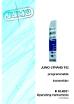
1.7.2 Structuring the user data for transmission of profile program
As can be seen from the above description, a telegram Class 62 and Object-ID 12 is necessary to
transmit one program section. The importance of the user data is summarized in Fig. 1. Here, the
different functions of the first three bytes have to be particularly noted (Pgm No., Phs No., Sect.
No.).
User
data (32
bytes
Nutzdaten
(max.
32max.)
Byte)
Pgm
PgmNo.
Nr.
Phs
Phs- Sect.
AbsNo.
Nr. No.
Nr.
effective
user data
(29 29
bytes
max.)
effekt. Nutzdat
(max.
Byte)
0-19
0-19
0-9
0-9
0-9
0-9
transmit one eines
Pgm section
(read and(Lesen
write) und Schreiben)
Uebertragung
Pgm-Abschnitts
0-19
0-19
-1
-1
any
bel.
delete one
program
(write only)
Loeschen
eines
Programms
(nur Schreiben)
0-19
0-19
0-9
0-9
10
10
transmit phase
(read and(Lesen
write) und Schreiben)
Uebertragung
dertime
Phasenzeit
-1-1
any
bel.
any
bel.
delete allaller
programs
(write only)
Loeschen
Programme
(nur Schreiben)
Fig. 1
For the transmission of program sections, the area of the effective user data is is filled with section
data as follows:
For Sect. No. 0 – 9 (6 bytes) :
unsigned long
unsigned long
unsigned int
V_circ;
SectTime;
Operctc[2];
/* circulation rate */
/* section run-time; bit 15 = 1 = h/min */
/* operating contacts 0 – 12 */
For Sect. No. 10 (2 bytes) :
unsigned long
PhsTime;
/* phase run-time; bit 15 = 1 = h/min */
A valid phase time can only be transmitted to the LPT-100 if at least one section in the corresponding phase was created first.
If an error is detected during transmission of a program section or the phase time, this will be indicated in the response telegram by Error = 1. The error code will then be saved in the structure variable “Number”.
In the event of an error, the user data of the LON response must not be evaluated!
12
9.00/LPT-100
Operation
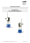
1.8 Connection diagram
Connection for
Terminals strip I
Measurement inputs
Chamber
temperature
Resistance thermometer
in 3-wire circuit
I1
I2
I3
Standard signal 0(4) – 20 mA
Vacuum
I4
I5
not to be used
I6
I7
I8
I9
LON interface
I 10
I 11
twisted pair cable
Technical earth
I 12
to connect screening against interference to termimal “PE“ of the
supply.
Connection for
Terminals strip II
Setpoint output 0 — 10 V
II 1
II 2
circulation rate 0 – 100%
Logic input 1
II 3
II 7
floating contact
GND
phase fast forward
Logic input 2
II 4
II 7
floating contact
GND
programming inhibit
Logic input 3
II 5
II 7
floating contact
GND
external start
Logic input 4
II 6
II 7
floating contact
GND
external stop
Count input
II 8
II 7
tumbler speed (floating contact), 2 Hz max.
GND
9.00/LPT-100
13
Operation
Connection for
Relay outputs
Terminals assignment
Terminals strip IV
Contact life:
106 operations at
rated load
Relay 1
Rating:
230 V 3A
(resistive load)
Relay 3
Relay 2
Relay 4
connectors must
Relay 5
only plugged and
unplugged when not
Relay 6
powered!
IV 1
IV 2
IV 3
IV 4
IV 5
IV 6
IV 7
IV 8
IV 9
IV10
IV11
IV12
(P) common
(S) n.o. make
(P) common
(S) n.o. make
(P) common
(S) n.o. make
(P) common
(S) n.o. make
(P) common
(S) n.o. make
(P) common
(S) n.o. make
Process unit
RC protection circuit
(metal film resistor 56R
0.5W,
metallized-plastic
capacitor 22nF / 1000V)
Terminals strip V
Relay 7
V13
V14
Relay 8 V15
V16
Relay 9 V17
V18
Relay 10 V19
V20
Relay 11 V21
V22
Relay 12 V23
V24
(P) common
(S) n.o. make
(P) common
(S) n.o. make
(P) common
(S) n.o. make
(P) common
(S) n.o. make
(P) common
(S) n.o. make
(P) common
(S) n.o. make
RC protection circuit
(metal film resistor 56R
0.5W,
metallized-plastic
capacitor 22nF / 1000V)
Terminals strip VII
Relay 13 VII 1
VII 2
Relay 14 VII 3
VII 4
Relay 15 VII 5
VII 6
Relay 16 VII 7
VII 8
Relay 17 VII 9
VII10
Relay 18 VII 11
VII 12
(P) common
(S) n.o. make
(P) common
(S) n.o. make
(P) common
(S) n.o. make
(P) common
(S) n.o. make
(P) common
(S) n.o. make
(P) common
(S) n.o. make
Switch S 103
Termination
resistance
Setting
open,
no bus termination
RC protection circuit
(metal film resistor 56R
0.5W,
metallized-plastic
capacitor 22nF / 1000V)
50Ohm
Terminals strip VIII
Relay 19 VIII 13
VIII 14
Relay 20 VIII 15
VIII 16
Relay 21 VIII 17
VIII 18
Relay 22 VIII 19
VIII 20
Relay 23 VIII 21
VIII 22
Relay 24 VIII 23
VIII 24
14
(P) common
(S) n.o. make
(P) common
(S) n.o. make
(P) common
(S) n.o. make
(P) common
(S) n.o. make
(P) common
(S) n.o. make
(P) common
(S) n.o. make
100Ohm
or
RC protection circuit
(metal film resistor 56R
0.5W,
metallized-plastic
capacitor 22nF / 1000V)
k
factory setting
9.00/LPT-100
Operation
9.00/LPT-100
15
M. K. JUCHHEIM GmbH & Co
JUMO Instrument Co. Ltd.
Street address:
Moltkestraße 13 - 31
36039 Fulda, Germany
Delivery address:
Mackenrodtstraße 14
36039 Fulda, Germany
Postal address:
36035 Fulda, Germany
Phone: +49 (0) 661 60 03-0
Fax:
+49 (0) 661 60 03-5 00
E-Mail: [email protected]
Internet: www.jumo.de
JUMO House
Temple Bank, Riverway
Harlow, Essex CM20 2TT, UK
JUMO PROCESS CONTROL INC.
735 Fox Chase,
Coatesville, PA 19320, USA
Phone: 610-380-8002
1-800-554-JUMO
Phone: +44 (0) 1279 63 55 33
Fax:
610-380-8009
Fax:
+44 (0) 1279 63 52 62
E-Mail: [email protected]
E-Mail: [email protected] Internet: www.JumoUSA.com