1
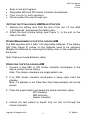
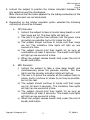
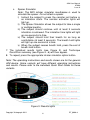
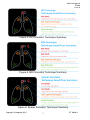
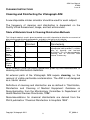
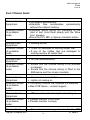
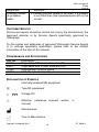
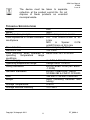
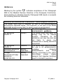
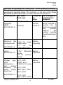
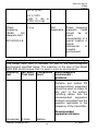
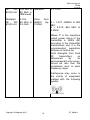
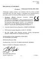
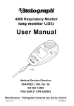
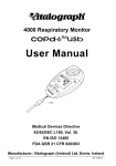
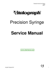
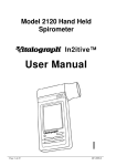
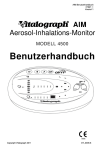
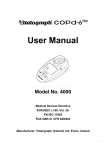
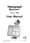
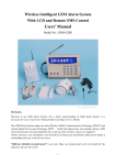
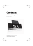
AIM User Manual 07608 Issue 1 Vitalograph AIM Aerosol Inhalation Monitor MODEL 4500 User Manual l Copyright Vitalograph 2011 DT_0006-8 AIM User Manual 07608 Issue 1 Vitalograph Ltd., Maids Moreton, Buckingham, MK18 1SW, England Phone: (01280) 827110 Fax: (01280) 823302 e-mail: [email protected] Vitalograph GmbH, Rellinger Straße 64a, 20257 Hamburg, Germany Phone: (040) 54 73 91-0 Fax: (040) 547 391 40 e-mail: [email protected] Vitalograph Inc., 13310 West 99th Street, Lenexa, Kansas 66215, U.S.A. Phone: (913) 888-4221 Fax: (913) 888-4259 e-mail: [email protected] Vitalograph (Irl.) Ltd., Gort Road Business Park, Ennis, Co. Clare, Ireland Phone: (065) 6864100 Fax: (065) 6829289 e-mail: [email protected] Internet: www.vitalograph.com © Copyright Vitalograph 2011 Current Edition (Issue 1) Cat. No. 07608 Vitalograph is a registered trademark Copyright Vitalograph 2011 DT_0006-8 AIM User Manual 07608 Issue 1 Table of Contents DESCRIPTION OF THE VITALOGRAPH AIM 2 FEATURES OF THE VITALOGRAPH AIM 3 GETTING THE VITALOGRAPH AIM READY FOR USE 4 POWER MANAGEMENT IN THE VITALOGRAPH AIM 4 OPERATING THE VITALOGRAPH AIM 4 CLEANING INSTRUCTIONS 8 CLEANING AND DISINFECTING THE VITALOGRAPH AIM FAULT FINDING GUIDE 8 9 CUSTOMER SERVICE 10 CONSUMABLES AND ACCESSORIES 10 EXPLANATION OF SYMBOLS 10 TECHNICAL SPECIFICATIONS 11 CE NOTICE 12 FDA NOTICE 17 DECLARATION OF CONFORMITY 18 GUARANTEE 19 Copyright Vitalograph 2011 DT_0006-8 i AIM User Manual 07608 Issue A DESCRIPTION OF THE VITALOGRAPH AIM The device (Aerosol Inhalation Monitor) is designed to enable a medical professional to objectively assess in detail how the test subject uses their inhaler. This detailed knowledge allows the medical professional to assess and coach the test subject in perfecting their inhalation technique. The main components for the Vitalograph AIM are shown in Figures 1 and 2. Single-use disposable DPI inhaler simulator MDI placebo canister (re-use until empty) User Interface Silicone Tubing Single-use disposable MDI inhaler simulator. (also required for spacer) AIM Device Figure 1: Components of the AIM Copyright Vitalograph 2011 DT_0006-8 2 AIM User Manual 07608 Issue A DPI simulator button MDI simulator button Spacer simulator button Power button Inhaler technique summary display Ready to inhale Flow lights Canister Activation (MDI) Inhalation time lights Battery low light End of breath-hold button Breath-hold lights Figure 2: Components of the AIM – User Interface FEATURES OF THE VITALOGRAPH AIM The Vitalograph AIM features include: • • • • • • • Assists in training patients to use their inhalers properly Inspiratory acceleration at the start of inspiration Timing of firing of MDI inhaler simulator Inspiratory flow rate throughout inspiration Inhalation time within target flow range Breath hold time at the end of inhalation Identifies and qualifies poor inhaler technique Copyright Vitalograph 2011 DT_0006-8 3 AIM User Manual 07608 Issue A • • • • Easy to use and hygienic. Disposable MDI and DPI inhaler simulator mouthpieces Clear sounds for audio feedback Device guides the user through use. GETTING THE VITALOGRAPH AIM READY FOR USE 1. Remove the battery door from the rear of the unit. Fit four AAA 1.5V batteries, and replace the battery door. 2. Attach the dual silicone tubing (see Figure 1), to the port on the side of the AIM. POWER MANAGEMENT IN THE VITALOGRAPH AIM The AIM operates with 4 AAA 1.5V disposable batteries. If the battery light (See Figure 2) comes on the batteries need to be replaced. Replace the batteries by removing the battery door on the underside of the device. Note: Dispose of used batteries safely. OPERATING THE VITALOGRAPH AIM 1. Connect a new MDI or DPI inhaler simulator mouthpiece to the device via the silicone tubing. Note: The inhaler simulators are single patient use. 2. If an MDI inhaler simulator mouthpiece is being used insert the placebo. Note: If a placebo is not fitted then flow measurements will not be correct. 3. Press the power button and select the inhaler simulator option - DPI simulator - MDI simulator - Spacer simulator 4. Instruct the test subject to breath fully out, but not through the inhaler simulator. Copyright Vitalograph 2011 DT_0006-8 4 AIM User Manual 07608 Issue A 5. Instruct the subject to position the inhaler simulator between the lips sealed around the mouthpiece. Note: Ensure that the holes adjacent to the tubing connection to the inhaler simulator are not obstructed. 6. Depending on the inhaler simulator option selected the following instructions should be followed: a. DPI Simulator i) Instruct the subject to take a forceful deep breath in until their lungs are full. The flow lights will light up. ii) The aim is to get the flow indicator into the green zone as quickly as possible, but not to inhale too fast. iii) The subject should continue to inhale until their lungs are full. The inhalation time lights will light up one second at a time. iv) The subject should hold their breath for as long as comfortable (at least 3 seconds). The breath hold lights will light up one second at a time. v) When the subject ceases breath hold, press the end of breath-hold button. b. MDI Simulator i) Instruct the subject to take a slow deep breath and simultaneously press the placebo canister. The flow lights and the canister activation lights will light up. ii) The aim is to press the canister as the subject starts to inhale, and to continue to inhale for as long as possible, but not too fast. iii) The subject should continue to inhale until their lungs are full (at least 3 seconds). The inhalation time lights will light up one second at a time. iv) The subject should hold their breath for as long as comfortable (at least 3 seconds). The breath hold lights will light up one second at a time. v) When the subject ceases breath hold, press the end of breath-hold button. Copyright Vitalograph 2011 DT_0006-8 5 AIM User Manual 07608 Issue A c. Spacer Simulator Note: The MDI inhaler simulator mouthpiece is used to simulate the spacer. Do not attach a spacer. i) Instruct the subject to press the canister just before or as inhalation starts. The canister activation lights will light up. ii) The Spacer Simulator allows the subject to take a single or multiple breaths. iii) The subject should continue until at least 3 seconds inhalation is achieved. The inhalation time lights will light up one second at a time. iv) The subject should hold their breath for as long as comfortable (at least 3 seconds). The breath hold lights will light up one second at a time. v) When the subject ceases breath hold, press the end of breath-hold button. 7. The individual results lights (see Figure 3) and Technique Good/Poor summary (see Figure 4 - 6) will then appear. 8. To repeat, press the appropriate inhaler simulator option button. Note: The operating instructions and results shown are for the generic AIM device. Some variants will have different operating instructions and results. Please refer to the individual Quick Start Guide for these variants. Figure 3: Results lights Copyright Vitalograph 2011 DT_0006-8 6 AIM User Manual 07608 Issue A Figure 4: DPI Simulator Technique Summary Figure 5: MDI Simulator Technique Summary Figure 6: Spacer Simulator Technique Summary Copyright Vitalograph 2011 DT_0006-8 7 AIM User Manual 07608 Issue A CLEANING INSTRUCTIONS Cleaning and Disinfecting the Vitalograph AIM A new disposable inhaler simulator should be used for each subject. The frequency of cleaning and disinfecting is dependent on the Facility’s Risk Assessment, usage, and test environment. Table of Materials Used & Cleaning/Disinfection Methods This listing of materials used is given to provide users with information to allow the assessment of other cleaning and disinfecting procedures available in the facility on this device. Part Material Clean/ Disinfect Autoclave Recommended Disinfectants Top Case Exterior Bottom Case Exterior Overlay label White Silicone Tubing ABS Clean No AMS Clean No PET Film Clean No Silicone Clean Viable Wiping with a 70% isopropyl alcohol impregnated cloth provides a suitable form of cleaning and low-level disinfection. This may be preceded by cleaning with an anti-static foam cleaner if necessary. Note: Always follow the safety guidelines given by the manufacturer of cleaning and disinfectant chemicals. All external parts of the Vitalograph AIM require cleaning, i.e. the removal of visible particulate contamination. The AIM is not designed as a ‘sterile’ device. Definitions of cleaning and disinfection are as defined in “Sterilization, Disinfection and Cleaning of Medical Equipment: Guidance on Decontamination from the Microbiology Committee to Department of Health Medical Devices Directorate, 1996”. Recommendations for chemical disinfectants are derived from the PHLS publication “Chemical Disinfection In Hospitals 1993”. Copyright Vitalograph 2011 DT_0006-8 8 AIM User Manual 07608 Issue A FAULT FINDING GUIDE Problem Fault Symptoms: Possible Causes: (In probable order) •Test begins automatically •Inhalation time accumulates automatically without the subject inhaling. •Flowhead and/or tubing not stationary at the start of test. Hold them steady until the ‘Blow Icon’ appears. •Press the DPI, MDI or Spacer simulator button. Problem Fault Symptoms: Possible Causes: (In probable order) • Rocking device Problem Fault Symptoms: Possible Causes: (In probable order) • No flow measurements. • Check for damaged or missing rubber feet. • If any of the rubber feet are damaged or missing replace all rubber feet. • Ensure that the silicone tubing is not pinched or trapped. • Ensure that the silicone tubing is fitted to the AIM device and the inhaler simulator. Problem Fault Symptoms: Possible Causes: (In probable order) • Cannot read user interface. • Lights not coming on • The battery may be low. Replace the batteries. • Main PCB failure – contact support. Problem Fault Symptoms: Possible Causes: (In probable order) • MDI simulator activation light not coming on. • Placebo canister is not fitted • Placebo canister is empty Problem Fault • Flow measurement appears low for the MDI Copyright Vitalograph 2011 DT_0006-8 Symptoms: 9 AIM User Manual 07608 Issue A Symptoms: Possible Causes: (In probable order) simulator. • Placebo canister needs to be fitted. If a placebo is not fitted then flow measurements will not be correct. CUSTOMER SERVICE Service and repairs should be carried out only by the manufacturer, the approved importer or by Service Agents specifically approved by Vitalograph. For the names and addresses of approved Vitalograph Service Agents or to arrange spirometry workshops, please refer to the contact information at the start of this manual. CONSUMABLES AND ACCESSORIES Cat. no 45610 45611 79192 45027 Description Disposable DPI Inhaler Simulator (25) Disposable MDI Inhaler Simulator (25) Replacement silicone tubing HFA Placebo Aerosol (8) EXPLANATION OF SYMBOLS Internally powered ME equipment k Type BF equipment V Voltage DC h Attention manual) (reference relevant section in Manufacturer Year of Manufacture Copyright Vitalograph 2011 DT_0006-8 10 AIM User Manual 07608 Issue A The device must be taken to separate collection at the product end-of-life. Do not dispose of these products as unsorted municipal waste. TECHNICAL SPECIFICATIONS Product AIM Model 4500 Flow detection principle Differential pressure sensor Flow impedance of inhaler simulator DPI: 0.49 cmH2O/L/min at 50 mouthpiece L/min MDI & Spacer: 0.016 cmH2O/L/min at 50 L/min Flow detection Flow sampling @ 20Hz Maximum flow 100 L/min Flow accuracy when operated in Better than ±5% or 5L/min operating temperature range conditions Power Supply 4 x AAA, 1.5V batteries Operating temperature range Design limits: 10–40ºC Safety standards EN ISO 60601:2006 {IEC 60601 -1:2005} QA/GMP standards EN ISO 13485:2003, CMDR SOR/98-282 & FDA 21 CFR 820 Size 165 mm x 133 mm x 39.6 mm Weight 260g (including batteries and tubing) Storage Temperature 0–50ºC Storage Relative Humidity 10%–95% Copyright Vitalograph 2011 DT_0006-8 11 AIM User Manual 07608 Issue A CE NOTICE l Marking by the symbol indicates compliance of the Vitalograph AIM to the Medical Devices Directive of the European Community. Such marking is indicative that the Vitalograph AIM meets or exceeds the following technical standards: Guidance and manufacturer’s declaration – electromagnetic emissions The Model 4500 AIM is intended for use in the electromagnetic environment specified below. The customer or the user of the Model 4500 AIM should assure that it is used in such an environment Compliance Electromagnetic Emissions test environment - guidance RF emissions Group 1 The Model 4500 AIM uses RF CISPR 11 energy only for its internal function. Therefore, its RF emissions are very low and are not likely to cause any interference in nearby electronic equipment. The Model 4500 AIM is suitable RF emissions Class B for use in all establishments, CISPR 11 including domestic Harmonic emissions Battery establishments and those IEC 61000-3-2 Operated directly connected to the public Voltage Battery low-voltage power supply Fluctuations/Flicker Operated network that supplies buildings emissions used for domestic purposes. IEC61000-3-3 Copyright Vitalograph 2011 DT_0006-8 12 AIM User Manual 07608 Issue A Guidance and manufacturer’s declaration – electromagnetic immunity The Model 4500 AIM is intended for use in the electromagnetic environment specified below. The customer or the user of the Model 4500 AIM should assure that it is used in such an environment Immunity test IEC 60601 Complian Electromagnetic environment Test level ce guidance level Electrostatic Floors should be ±6 kV contact ±6 kV discharge wood, concrete or contact (ESD) ceramic tile. If ±8 kV air ±8 kV air IEC 61000-4-2 floors are covered with synthetic material, the relative humidity should be at least 30%. Electrical fast ±2kV for power Battery transient/burst Operated supply lines ±1 kV for IEC 61000-4-4 input/output lines Surge IEC 61000-4-5 ±1kV differential Battery Operated mode ±2 kV common mode Voltage dips, short interruptions and voltage variations on power supply input lines Battery <5 % 100V Operated (>95% dip in 100V) for 0.5 cycle IEC 61000-4-11 70 % 100V (30 % dip in 100V) 40 % 100V (60% dip in 100V) for 5 cycles Copyright Vitalograph 2011 DT_0006-8 13 AIM User Manual 07608 Issue A for 25 cycles <5 % 100V (>95 % dip in 100V) for 5 sec Power 3 Α/m frequency (50/60 Hz) magnetic field Not Applicable IEC 61000-4-8 Power frequency magnetic fields should be at levels characteristic of a typical location in typical commercial or hospital environment. Guidance and manufacturer’s declaration – electromagnetic immunity The Model 4500 AIM is intended for use in the electromagnetic environment specified below. The customer or the user of the Model 4500 AIM should assure that it is used in such an environment Immunity IEC 60601 Compliance Electromagnetic environment test Test level level guidance Portable and mobile RF communications equipment should be used no closer to any part of the system, including cables, than the recommended separation distance calculated from the equation applicable to the frequency of the transmitter. Recommended separation distance Conducted 3 Vrms Battery Copyright Vitalograph 2011 DT_0006-8 14 AIM User Manual 07608 Issue A RF. IEC 150 kHz to operated 61000-4-6 80 MHz in ISM bands d = 1.2√P Radiated 3 V/m 3V/m from RF. IEC 80 MHz to 80MHz top d = 1.2√P…80MHz to 800 61000-4-3 2.5 GHz 2.5GHz MHz d = 2.3√P…800 MHz to 2.5GHz Where P is the maximum output power rating of the transmitter in Watts (W) according to the transmitter manufacturer and d is the recommended separation distance in metres (m) Field strengths from fixed RF transmitters, as determined by an electromagnetic site survey, should be less than the compliance level in each frequency range. Interference may occur in the vicinity of equipment marked with the following symbol: Copyright Vitalograph 2011 DT_0006-8 15 AIM User Manual 07608 Issue A Recommended separation distances between portable and mobile RF communication equipment and the Model 4500 AIM The Model 4500 AIM is intended for use in an electromagnetic environment in which radiated RF disturbances are controlled. The customer or the user of the Model 4500 AIM can help prevent electromagnetic interference by maintaining a minimum distance between portable and mobile RF communications equipment (transmitters) and the Model 4500 AIM as recommended below, according to the maximum output power of the communications equipment. Rated maximum Separation distance according to frequency of output power of transmitter transmitter m 150 kHz to 80 80 MHz to 800 800 MHz to W MHz MHz 2.5GHz d = 1.2√P d = 1.2√P d = 2.3√P 0.01 0.1m 0.1m 0.2m 0.1 0.4m 0.4m 0.7m 1 1.2m 1.2m 2.3m 10 3.7m 3.7m 7.4m 100 11.7m 11.7m 23.3m For transmitters rated at a maximum output power not listed above, the recommended separation distance d in metres (m) can be estimated using the equation applicable to the frequency of the transmitter, where P is the maximum output power rating of the transmitter in watts (w) according to the transmitter manufacturer. NOTE 1 At 80 MHz and 800 MHz, the separation distance for the higher frequency range applies. NOTE 2 These guidelines may not apply in all situations. Electromagnetic propagation is affected by absorption and reflection from structures, objects and people. Medical Devices may be affected by cellular telephones and other personal or household devices not intended for medical facilities. It is recommended that all equipment used near the Vitalograph product comply with the medical electromagnetic compatibility standard and to Copyright Vitalograph 2011 DT_0006-8 16 AIM User Manual 07608 Issue A check before use that no interference is evident or possible. If interference is suspected or possible, switching off the offending device is the normal solution, as is required in aircraft and medical facilities. Medical electrical equipment needs special precautions regarding EMC and needs to be installed and put into service according to the EMC information provided, Portable and mobile RF communications equipment can affect medical electrical equipment. FDA NOTICE Caution: Federal law restricts this device to sale by, or on the order of the physician. Copyright Vitalograph 2011 DT_0006-8 17 AIM User Manual 07608 Issue A DECLARATION OF CONFORMITY Product: Vitalograph Model 4500 AIM Vitalograph hereby ensures and declares that the above product associated with this user manual, is designed and manufactured in accordance with the following QMS regulations and standards: • European Medical Devices Directive {MDD} 93/42/EEC, as amended. This device is classified as 1 with a measuring function per Annex IX of the MDD also meets the provisions of the Essential Requirements, Annex I, via compliance with Annex II of the Medical Devices Directive as per Article 11, section 3a, excluding point 4 of Annex II. • Canadian Medical Device Regulation {CMDR SOR/98-282} • FDA Quality System Regulation {QSR} 21 CFR 820. • EN ISO 13485: 2003. Medical devices. Quality management systems. Requirements for regulatory purposes. Certifying Body: British Standards Institute {BSI}. {For 93/42/EEC and CMDR}. BSI Notified Body #: 0086 Certificate Nos. CE 00772, CE 85553, MD 82182, FM 83550 Signed on behalf of Vitalograph (Ireland) Ltd. B. R. Garbe. Group Managing Director Copyright Vitalograph 2011 DT_0006-8 18 AIM User Manual 07608 Issue A GUARANTEE Subject to the conditions listed below, Vitalograph Ltd. and its associated companies, (hereinafter called the Company) guarantee to repair or at its option replace any component thereof, which, in the opinion of the Company is faulty or below standard as a result of inferior workmanship or materials. The conditions of this Guarantee are: 1. This Guarantee shall only apply to hardware defects which are notified to the Company or to its accredited distributor within 1 year of the date of purchase of the equipment, unless otherwise agreed in writing by the Company. 2. Software (meaning computer software, or user installable modules) is guaranteed for 90 days from the date of purchase. 3. The Company warrants that the software when correctly used in conjunction with the hardware will perform in the manner described in the Company's literature and user manuals. The Company undertakes to rectify at no expense to the customer any software failure notified within the period stated above, provided that the failure can be recreated and the software has been installed and used in accordance with the user manual. Notwithstanding this clause, the software is not warranted to be free of errors. 4. This Guarantee does not cover any faults caused by accident, misuse, neglect, tampering with the equipment, use of consumable items or parts not approved by the Company, or any attempt at adjustment or repair other than by personnel accredited by the Company, nor does it cover reinstatement of any configuration changes caused by the installation of any software. 5. If a defect occurs please contact the supplier from it was purchased for advice. The Company does not authorize any person to create for it any other obligation or liability in connection with Vitalograph® equipment. 6. This Guarantee is not transferable and no person, firm or company has any authority to vary the terms or conditions of this guarantee. 7. To the maximum extent permitted by law, the Company does not accept liability for any consequential damages arising out of the use of, or inability to use any Vitalograph® equipment. 8. This Guarantee is offered as an additional benefit to the Consumer's statutory rights and does not affect these rights in any way. Copyright Vitalograph 2011 DT_0006-8 19