1
OMRON
CHAPTER 1 – Technical Specification
CX-Programmer
User Manual
Version 2.1
Revision 2.1
Page 1
OMRON
CX-Programmer – User Manual
Notice
OMRON products are manufactured for use according to proper procedures by a qualified operator and
only for the purposes described in this manual.
The following conventions are used to indicate and classify precautions in this manual. Always heed the
information provided in them. Failure to heed precautions can result in injury to people or damage to
the product.
DANGER!
Indicates information that, if not heeded, is likely to result in loss of life or
serious injury.
WARNING
Indicates information that, if not heeded, could possibly result in loss of life
or serious injury.
Caution
Indicates information that, if not heeded, could result in relatively serious or
minor injury, damage to the product, or faulty operation.
OMRON Product References
All OMRON products are capitalised in this manual. The word “Unit” is also capitalised when it refers
to an OMRON product, regardless of whether or not it appears in the proper name of the product.
The abbreviation “PLC” means Programmable Logic Controller and is not used as an abbreviation for
anything else.
Revision 2.1
Page 2
OMRON
CX-Programmer – User Manual
Visual Aids
The following headings appear in the left column of the manual to help you locate different types of
information.
Indicates information of particular interest for efficient and convenient operation of the product.
1, 2, 3… Indicates lists of one sort or another, such as procedures, checklists etc.
Represents a shortcut on the Toolbar to one of the options available on the menu of the same
window.
OMRON, 2001
All rights reserved. No part of this publication may be reproduced, stored in a retrieval system, or
transmitted, in any form, or by any means, mechanical, electronic, photocopying, recording, or otherwise,
without the prior written permission of OMRON.
All copyright and trademarks acknowledged.
No patent liability is assumed with respect to the use of the information contained herein. Moreover,
because OMRON is constantly striving to improve its high-quality products, the information contained
in this manual is subject to change without notice. Every precaution has been taken in the preparation
of this manual. Nevertheless, OMRON assumes no responsibility for errors or omissions. Neither is any
liability assumed for damages resulting from the use of the information contained in this publication.
Revision 2.1
Page 3
OMRON
CX-Programmer – User Manual
About this Manual
This manual describes the CX-Programmer application and its ability to create and maintain programs
for use with OMRON SYSMAC CS, CV and C PLCs. It does not provide detailed information
concerning the PLCs themselves, for this information the commercial manual for the device must be
consulted.
This manual contains the following chapters:
•
Chapter 1 Introduction. This chapter describes the CX-Programmer software in general terms and
also provides details of the operating environment and minimum configuration necessary for the
satisfactory operation of CX-Programmer.
•
Chapter 2 Quick Start Guide. This chapter describes the basic features of CX-Programmer together
with a simple tutorial for familiarisation purposes.
•
Chapter 3 Project Reference. This describes the features common to two or more parts of CXProgrammer.
•
Chapter 4 Reference. This chapter introduces the features contained in the Project workspace and
discusses their associated commands and features.
•
Chapter 5 Advanced Topics. This chapter discusses the more advanced topics in relation to CXProgrammer.
•
Appendix A Toolbars and Keyboard Shortcuts. This appendix summarises the toolbar and keyboard
shortcuts available from CX-Programmer.
A Glossary of Terms and Index are also provided.
Warning:
Revision 2.1
Failure to read and understand the information provided in this manual
may result in personal injury or death, damage to the product, or
product failure. Please read each chapter in its entirety and be sure
you understand the information provided in the chapter and related
chapters before attempting any of the procedures or operations given.
Page 4
OMRON
CX-Programmer – User Manual
Table of Contents
CX-Programmer – User Manual.................................................. Page
Chapter 1 - Technical Specification ................................................... 1
OMRON CX-Programmer...........................................................................................................1
About this Manual .......................................................................................................................1
CX-Programmer Features............................................................................................................2
System Requirements ..................................................................................................................4
Installation ...................................................................................................................................5
Help and How to Access it ..........................................................................................................6
Technical Support........................................................................................................................9
Chapter 2 - Quick Start Guide ......................................................... 11
Starting CX-Programmer...........................................................................................................11
Licensing ...................................................................................................................................12
Introducing CX-Programmer Projects .......................................................................................12
The CX-Programmer Environment ...........................................................................................13
Using CX-Programmer..............................................................................................................21
Summary....................................................................................................................................32
Chapter 3 - Project Reference .......................................................... 33
Project Workspace.....................................................................................................................33
Program Sections.......................................................................................................................34
Cross-Reference Report.............................................................................................................36
Address Reference Tool ............................................................................................................37
Output Window .........................................................................................................................39
Watch Window..........................................................................................................................39
Options and Preferences ............................................................................................................41
Finding and Replacing Text.......................................................................................................47
Properties...................................................................................................................................53
Using Microsoft Windows Features in CX-Programmer ..........................................................55
Chapter 4 - Reference........................................................................ 67
PLCs and Projects......................................................................................................................67
Symbols .....................................................................................................................................68
Program Editing.........................................................................................................................78
Mnemonics Program Editing.....................................................................................................88
Working On-Line ......................................................................................................................88
Flash ROM Backup ...................................................................................................................99
Data Trace/Time Chart Monitoring .........................................................................................100
CX-Net Network Configuration Tool......................................................................................100
IO Table...................................................................................................................................101
Revision 2.1
Page 5
OMRON
CX-Programmer – User Manual
Table of Contents continued
Page
Chapter 5 - Advanced Topics ......................................................... 103
Writing More Maintainable Programs .....................................................................................103
Copying Information between Projects ...................................................................................104
Using CX-Programmer with Other Applications.....................................................................104
Converting Programs to PLC Types........................................................................................108
Applying a Password to the PLC Program ..............................................................................109
Appendix A - Toolbar and Keyboard Shortcuts .......................... 111
Standard Toolbar .....................................................................................................................111
Diagrams Toolbar ....................................................................................................................112
Symbol Table Toolbar .............................................................................................................112
Insert Toolbar ..........................................................................................................................113
PLC Toolbar ............................................................................................................................113
Program Toolbar......................................................................................................................114
Views Toolbar .........................................................................................................................114
Keyboard Shortcuts .................................................................................................................115
Glossary of Terms............................................................................ 117
Index.................................................................................................. 123
Revision 2.1
Page 6
OMRON
Chapter 1 – Technical Specification
CHAPTER 1
Technical Specification
This chapter describes the CX-Programmer software in general terms and provides details of the
operating environment and minimum configuration necessary for the satisfactory operation of CXProgrammer.
CX-Programmer Software
CX-Programmer is a PLC programming tool for the creation, testing and maintenance of programs
associated with Omron CS1-series PLCs, CV-series PLCs and C-series PLCs. It provides facilities for
the support of PLC device and address information and for communications with OMRON PLCs and
their supported network types.
CX-Programmer operates on IBM compatible personal computers with Pentium or better central
processors, including Pentium II. It runs in a Microsoft Windows environment (Microsoft Windows 95,
98, Millennium or 2000 and NT4.0 with Service Pack 5 or later).
About this Manual
This User Manual acts as a reference for CX-Programmer by describing its various concepts and abilities,
and by leading the user through the basics of CX-Programmer programming. It also provides a detailed
reference for all of the CX-Programmer functions.
Separate OMRON manuals describe the PLC programming structure and instruction set in detail. A
separate OMRON manual describes the common features to PLC programming used by software other
than CX-Programmer.
CX-Programmer comes with a context sensitive on-line help system which is designed
to complement this manual and to provide a quick reference at any point while using
CX-Programmer when the manual is not to hand. This general help system uses a fast
‘hypertext system’ which allows progressively more information about any topic to be
obtained by selecting keywords within the descriptive text.
Throughout this manual it is assumed that the reader has a working knowledge of Microsoft Windows,
and knows how to:
♦
Use the keyboard and mouse.
♦
Select options from Microsoft Windows menus.
♦
Operate dialogue boxes.
♦
Locate, open and save data files.
♦
Edit, cut and paste text.
♦
Use the Microsoft Windows desktop environment.
Revision 2.1
Page 1
OMRON
CHAPTER 1 – Technical Specification
If Microsoft Windows has not been used before, it is recommended that the reader spends some time
working with it using the Microsoft documentation before using CX-Programmer.
This manual also assumes that a working knowledge of OMRON PLC devices has been obtained.
CX-Programmer Features
CX-Programmer is a support tool for the programming of OMRON PLCs and for maintenance of their
device settings. It supersedes the OMRON applications SYSWIN and SYSMAC-CPT.
The following list describes important features that were present in CX-Programmer 2.0.
♦
Support for program ‘sections’ - a program can be divided into definable, named sections, for easier
management of large programs.
♦
Improved search / replace - including wildcards and memory range movement.
♦
Improved ladder and mnemonic editors, with much greater clarity, and improved zooming.
♦
It is possible to choose the format and amount of symbol information to show on the ladder display
to maximise the use of space – display of comments can be quickly turned off and on.
♦
The ladder editor automatically justifies a ladder rung when the cursor is moved off it.
♦
Use of colour - global and local symbols are coloured differently in the ladder / mnemonic views.
Errors in ladder elements are shown a definable 'Error' colour.
♦
The shortcut keys and toolbars can be customised.
♦
An instruction can be entered using its instruction number, in the new instruction dialogue.
♦
Improved 'go to' facilities - go to an input or output function using a particular address, and go back
again. Or go to a rung/step or commented rung.
♦
The watch window supports local symbols.
♦
Monitoring can be paused, or frozen, to examine the logic of a program.
♦
A comment can be ‘attached’ to a ladder element (contact/coil or instruction).
♦
Monitoring can be set to work in hexadecimal format only.
♦
Addresses which are included within the PLC IO table are shown with an I / Q prefix in the
programming windows.
♦
It is possible to define what is shown on the split in an editing window - the same type of view,
ladder/mnemonic, or the local symbol table.
♦
Improved support for importing / exporting symbols to spreadsheets and text-editors.
♦
The value of a NUMBER data-type symbol can be given in hexadecimal.
♦
Improved ladder printing.
♦
Improved CX-Server components.
Revision 2.1
Page 2
OMRON
CHAPTER 1 – Technical Specification
Version 2.1 of CX-Programmer offers the following enhancements.
♦
Support for new PLCs – Full support has been added for the, CS1G-H, CS1H-H and CJ1G, CJ1G-H,
CJ1H-H series PLCs and the D/S Gateway PLC “(CPM2*-S*).
♦
Flash ROM backup – Flash ROM backup is supported for the PLCs incorporating this feature.
♦
Find and Replace – Enhanced and extended Find and Replace functionality. The GUI has been
enhanced to include the scope of the search i.e. whether the Section, Global symbol and/or the Local
symbol will be affected by the search.
♦
Upload/Download – The Upload/Download functionality has been updated to include the
CV/CVM1, CS1/CJ1, CJ1H/H-H and CS1G/H-H PLCs to avoid searching section markers on the
initial dialog Upload.
♦
The range of the Send/Rec. instruction has been extended to include the PLCs CS1/CJ1, CS1G/H-H
and CJ1G/H-H
♦
Operation – The levels of operation have been extended to include Junior, Demo and Trial versions
of the product.
♦
Symbol Sorting – The symbol sort for number data types has been enhanced and is now sorted
separately from other data types in the symbol table view.
Direct import file range extended to include CPT, SP1 and COD files.
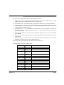
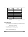
CX-Programmer supports the following PLCs.
Revision 2.1
Series
Model
CJ1-Series
CJ1G
CPU Types
CJ1-Series
CJ1G-H
CPU 42, CPU 43, CPU 44 and CPU 45
CJ1-Series
CJ1H-H
CPU 65 and CPU 66.
CS1-Series
CS1G
CS1G-H
CPU 42, CPU 43, CPU 44, CPU 45
CS1-Series
CS1H
CS1H-H
CPU 63, CPU 64, CPU 65, CPU 66, CPU 67
CV-Series
CV1000
CPU 01
CV-Series
CV2000
CPU 01
CV- Series
CV500
CPU 01
CV- Series
CVM1
CPU 01, CPU 11
CV- Series
CVM1-V2
C- Series
C1000H
CPU 01
C- Series
C2000H
CPU 01
C- Series
C200H
CPU 01, CPU 02, CPU 03, CPU 11, CPU 21,
CPU 22, CPU 23, CPU 31
C- Series
C200HE
CPU 44, CPU 45
CPU 01, CPU 11, CPU 21
CPU 11, CPU 32, CPU 42
Page 3
OMRON
CHAPTER 1 – Technical Specification
Series
Model
CPU Types
C- Series
C200HE-Z
C- Series
C200HG
CPU 33, CPU 43, CPU 53, CPU 63
C- Series
C200HG-Z
CPU 33, CPU 43, CPU 53, CPU 63
C- Series
C200HS
CPU 01, CPU 03, CPU 21, CPU 23, CPU 31,
CPU 33
C- Series
C200HX
CPU 34, CPU 44, CPU 54, CPU 64
C- Series
C200HX-Z
CPU 34, CPU 44, CPU 54, CPU 64, CPU 65,
CPU 85
C- Series
CPM1
(CPM1A)
CPU 10, CPU 20, CPU 30, CPU 40
C-Series
CPM2*
CPM2*-S*
CPU 10, CPU 20, CPU 30
C- Series
CQM1
C- Series
CQM1H
IDSC
–
CPU 11, CPU 32, CPU 42
CPU 11, CPU 21, CPU 41, CPU 42, CPU 43,
CPU 44, CPU 45
CPU 11, CPU 21, CPU 51, CPU 61
–
SRM1
SRM1
C01, C02
SRM1
SRM1-V2
C01, C02
Note:
The CVM1-V1 PLC for types CPU01 and CPU11 cannot be specifically selected. Use
the non V2 types.
Refer to the CX-Server PLC Tools User Manual for information regarding available communication
types.
System Requirements
CX-Programmer operates on IBM compatible personal computers with Pentium or better central
processors, including Pentium II. It runs in a Microsoft Windows environment (Microsoft Windows 95,
98, Millennium or 2000 and NT4.0 with Service Pack 5 or later).
Note:
CX-Programmer is not guaranteed to be compatible with computers running Windows
emulation (for example, Apple Macintosh).
The following configuration is the minimum system requirements for running CX-Programmer in
Microsoft Windows 95, 98 and NT4.0 (Service Pack 5 or later,).
♦
IBM PC-AT compatible or NEC PC-98 compatible computer;
♦
Pentium class CPU operating at 133 Megahertz (MHz) or faster;
♦
Minimum 32 Megabytes (Mb) Random Access Memory (RAM);
♦
Hard disk storage with at least 100 Mb free space;
♦
800 × 600 SVGA or higher resolution display system is recommended.
Revision 2.1
Page 4
OMRON
CHAPTER 1 – Technical Specification
The following configuration is the minimum system requirements for running CX-Programmer in
Microsoft Windows 2000 and Millennium edition.
♦
IBM PC-AT compatible or NEC PC-98 compatible computer;
♦
Pentium class CPU operating at 150 Megahertz (MHz) or faster;
♦
Minimum 64 Megabytes (Mb) Random Access Memory (RAM);
♦
Hard disk storage with at least 100 Mb free space;
♦
800 × 600 SVGA or higher resolution display system is recommended.
The following is the recommended minimum system environment.
♦
IBM PC-AT compatible or NEC PC-98 compatible computer;
♦
Pentium class CPU operating at 200 Megahertz (MHz) or faster;
♦
64 Megabytes (Mb) Random Access Memory (RAM);
♦
A minimum of 150 Mb free hard disk space;
♦ 1024 × 786 SVGA or higher resolution display.
Use of a mouse is highly recommended, although all operations can be performed using the keyboard.
Refer to the on-line help or the User Manual for a list of keyboard shortcut commands.
The amount of RAM and hard disk space used depends upon the size of the PLC programs written –
approximately 1K per step.
Installation
This chapter describes the procedures involved in the installation of CX-Programmer on a standard
workstation running Microsoft Windows 95, 98, Millennium or 2000 and NT4.0 with Service Pack 5 or
later.
The software is supplied on CD-ROM and is installed easily from within Microsoft Windows. The
installation can be terminated at any point during the installation process.
During the installation process the Software Licence Agreement will be displayed. This informs you of
Omron’s terms and conditions concerning the software licensing of CX-Programmer. These must be read
and agreed with before continuing.
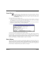
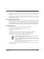
1, 2, 3…
Revision 2.1
1.
Insert the CD in the appropriate CD-ROM drive. If autorun is set you will
automatically be taken to the Install screen. If not select Start then the Run option
from the Start pushbutton on the Microsoft Windows taskbar.
2.
Click the Browse pushbutton to select the setup file from the CD-ROM drive.
3.
Click the OK pushbutton to initiate the installation.
instructions.
Follow the on-screen
Page 5
OMRON
CHAPTER 1 – Technical Specification
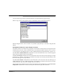
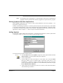
Entering a Licence Number
During the installation, a licence number must be entered. The licence number is supplied with the
purchase of CX-Programmer. There are six different licence number types representing six different
modes of installation. Upgrade licence numbers are available on request.
The six installation modes are:
Full (1 User)
Installation providing full functionality support for all PLCs.
The licence is restricted to a single user installation.
Full (3 User)
Installation providing full functionality support for all PLCs.
The licence is restricted to a three user installation.
Full (10 User)
Installation providing full functionality support for all PLCs.
The licence is restricted to a ten user installation.
Junior
Installation providing full functionality support for the junior range PLCs only
CPM1 (CPM1A, CPM2*, SRM1, SRM1-V2).
The licence is restricted to a single user installation.
Trial
Installation providing full functionality support for all PLCs. Its use is limited to
30 days from time of installation.
The licence is restricted to a single user installation.
Demonstration
Installation providing limited functionality support for all PLCs. Full system
operation is provided but projects can not be saved or printed.
If no licence number is entered then CX-Programmer is automatically installed in demonstration mode.
If CX-Server was included in the installation then on completion of the CX-Programmer installation a
number of dialogs will prompt for information concerning the installation of CX-Server and its
components.
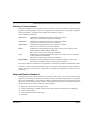
Help and How to Access it
CX-Programmer comes with a detailed context-sensitive help system. At any time while using the
software, it is possible to get help on the particular point that is currently being worked on, or on general
aspects of CX-Programmer. This system is intended to complement the manual, by providing an on-line
reference to specific functions of the software. The manual is designed to provide tutorial information
and discuss the various facilities offered by CX-Programmer.
♦
Help topics (available from the Help menu);
♦
Instruction Reference (available from the Help menu and from the instruction entry dialogue);
♦
Context sensitive help;
♦
About (available from the Help menu);
♦
Status Bar.
Revision 2.1
Page 6
OMRON
CHAPTER 1 – Technical Specification
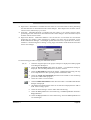
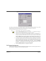
Help Topics
Select the Help Topics option on the Help menu. The Help system provides a standard look-up dialogue
under the Contents tab showing the contents of the CX-Programmer Help file. Double-click on an item
to read the associated information.
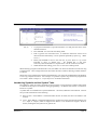
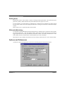
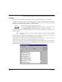
Index
Use the following procedure to retrieve on-line help from the Index tab of the Help Topics dialogue.
1, 2, 3…
1.
Select the Help Topics option from the Help menu.
2.
Select the Index tab.
3.
Enter a text query into the first step field. The second step field is refreshed
according to the query entered in the first step field.
4.
Select an entry in the second step field and select the Display pushbutton, or
double-click on the index entry.
5.
If an entry is linked to two or more topics, the names of the topics are displayed in
the Topics Found dialogue. Select a topic and choose the Display pushbutton or
double-click on the topic.
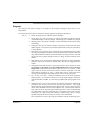
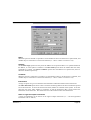
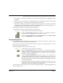
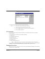
Find
Use the following procedure to retrieve on-line help from the Find tab of the Help Topics dialogue.
1, 2, 3…
1.
Select the Help Topics option from the Help menu.
2.
Select the Find tab.
3.
Enter a text query into the first step field. The second step field is refreshed
according to the query entered in the first step field. Previous text queries can be
retrieved by selecting from the drop-down list in the first step field.
4.
Select a word that matches the query – some words may be automatically selected.
More than one word can be selected by pressing Shift and selecting another word
to extend the selection or by pressing Ctrl and selecting another word to add to the
selection. The third step field is refreshed according to the word or words selected.
The number of topics found is shown at the bottom of the dialogue.
5.
Select a topic from the third step field and select the Display pushbutton, or
double-click on the topic from the third step field. Select the Clear pushbutton to
restart the Find operation.
The Find operation can be enhanced by the use of the Options pushbutton and Rebuild push-button.
Refer to Microsoft Windows documentation for further information.
Revision 2.1
Page 7
OMRON
CHAPTER 1 – Technical Specification
Instruction Reference
CX-Programmer supports additional help for CS1-series PLCs, CV-series PLCs and C-series PLCs. All
valid instructions relating to PLC programming can be retrieved by selecting Instruction Reference from
the Help menu, followed by either CS1-Series, CV-Series or C-Series. Individual help topics are
displayed.
Context Sensitive Help
CX-Programmer supports the use of context sensitive help. The relevant on-line help topic is provided
automatically by selecting the current area of the display responsible for carrying out those actions.
Select the F1 function key to retrieve context sensitive help. Some dialogs include a Help pushbutton
when F1 cannot be accessed.
It is also possible to retrieve context sensitive help by selecting the Help button from
the toolbar and selecting an area of the display to retrieve help.
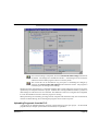
About CX-Programmer
CX-Programmer includes an About button accessible from the toolbar. The About CXProgrammer dialogue supplies technical reference information about the application
such as version and copyright information. It also contains essential version number
information that is required for obtaining technical support.
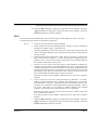
Status Bar
The status bar is displayed at the bottom of many of the CX-Programmer display and tool windows. It
provides several helpful pieces of information while programming:
♦
Instant Help. A brief message appears in the status bar as menu commands and buttons are selected.
♦
On-line Status. This shows the on-line or off-line status of the PLC. If connection to a PLC is lost,
the status bar will indicate this by flashing.
♦
PLC Operating Mode. When connected to a PLC, this shows the current PLC mode. Connection
errors are also displayed here.
♦
Connected PLC and CPU Type. The currently connected PLC and associated CPU can always be
referenced in the status bar.
♦
PLC Cycle Time. This shows the current cycle time of the PLC when connected.
♦
Cursor Position. This shows the position of the cursor within the program.
♦
On-line Edit Buffer Size. This shows the size remaining in the on-line edit buffer when connected
to a PLC and editing on-line.
The CX-Programmer status bar can be enabled and disabled by selecting the Status Bar option from the
View menu.
Revision 2.1
Page 8
OMRON
CHAPTER 1 – Technical Specification
Technical Support
If the installation instructions for this application have been followed (refer to Chapter 1 - Installation),
no difficulties should be encountered. However, if there is a problem, contact Customer Services.
If a problem occurs, check that it does not relate to a fault outside CX-Programmer, for instance, with
CX-Server components. Check the following:
♦
The computer is working correctly.
♦
The PLC is working correctly.
♦
The communications system is set up correctly.
♦ The errors are cleared in the PLC.
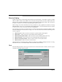
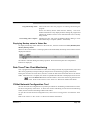
When Customer Services need to be contacted, keep the following details to hand. A clear and concise
description of the problem is required, together with the exact text of any error messages.
Note:
Revision 2.1
Use the About dialogue to obtain the version number of the application (the fourfielded version listed against the ‘CX-P.exe’ entry in the bottom list).
Page 9
OMRON
CHAPTER 1 – Technical Specification
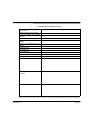
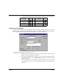
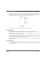
Customer Services Request Form
Version number of CXProgrammer:
Serial number of the software:
Operating system and version
number:
Language of operating system:
PLC type, model and CPU
details:
Type of communications in use:
Serial
SYSMAC LINK
SYSMAC NET
Controller Link
Ethernet
Toolbus
Nature of the problem:
Steps taken to reproduce
problem:
Other comments:
Refer to the CX-Server PLC Tools User Manual for support details regarding CX-Server components.
Revision 2.1
Page 10
OMRON
CHAPTER 2 – Quick Start Guide
CHAPTER 2
Quick Start Guide
This chapter describes the basic features of CX-Programmer together with a simple tutorial for
familiarisation purposes; detail is to be found in Chapter 3 - Project Reference and Chapter 4 Reference.
As this chapter proceeds, important concepts about CX-Programmer are introduced by
this symbol.
Starting CX-Programmer
CX-Programmer is activated from the Start button in the Microsoft Windows taskbar.
Once activated, CX-Programmer is displayed.
CX-Programmer provides the facility to create a project file in which as many PLCs as required can be
included. For each PLC, ladder program(s), addressing and network details, pre-set PLC memory, IO
table, expansion instructions (if applicable) and programming symbols can be defined.
Revision 2.1
Page 11
OMRON
CHAPTER 2 – Quick Start Guide
Licensing
CX-Programmer uses a licence number system in order to activate the programme in one of four modes
of operation. The licence number for the mode of operation purchased is shown on the CD case.
Junior Mode
To use CX-Programmer in Junior mode, a licence number is required. Using this mode provides full
functionality but restricts programming to the CPM1(CPM1A), CPM2*, SRM1 and SRM1-V2 PLCs
only.
Trial Mode
A licence number is required to run CX-Programmer in Trial mode. Full functionality is provided is this
mode but operation is restricted to 30 days from the time installation.
Demo Mode
A licence number is not required to run CX-Programmer in Demo mode. Full system operation is
provided but projects can not be saved or printed.
Full Version
To access the Full Version of CX-Programmer, the appropriate licence number must be entered.
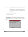
The licence number may be input at the time of installation or later. To enter an upgrade licence number
or re-enter the existing number after installation, follow these steps:
1, 2, 3…
1.
Start CX-Programmer, as described above.
2.
Click the help button in the toolbar or from the Help menu select the About CXProgrammer option.
3.
In the ‘About CX-Programmer’ dialog click the Licence button.
4.
A dialogue is displayed that allows a new licence number to be entered. Read the
warning message, enter the appropriate licence number and click OK.
5.
When a correct licence number is entered, CX-Programmer must be restarted to
gain full functionality.
Introducing CX-Programmer Projects
The information within a CX-Programmer project consists of ladder program(s),
operands, required PLC memory contents, IO tables, expansion instructions (if
applicable) and symbols. Each CX-Programmer project file is separate and is a single
document.
CX-Programmer can only open a single project at a time. However, it is possible to
deal with many project files by using CX-Programmer at once.
Revision 2.1
Page 12
OMRON
CHAPTER 2 – Quick Start Guide
A CX- Programmer project has a .CXP or .CXT file extension. (normally the .CXP file
is used, and is a compressed version of the .CXT file).
Once the project itself is created the desired PLC and symbol information can be defined. For a full
discussion of PLCs, refer to the CX-Server - PLC Tools User Manual.
The CX-Programmer Environment
This chapter describes how to manipulate the different views of the main window. Use
this chapter to develop an understanding with the layout of CX-Programmer and to
customise it according to specific requirements.
The views available are controlled via the options supplied by the View menu.
Revision 2.1
Page 13
OMRON
CHAPTER 2 – Quick Start Guide
The project workspace. Select the Toggle Project Workspace button from the toolbar
to activate this view. Deselect the Toggle Project Workspace button from the toolbar
to deactivate this view.
The Output window. Select the Toggle Output Window button from the toolbar to
activate this view. Deselect the Toggle Output Window button from the toolbar to
deactivate this view.
The Watch window. Select the Toggle Watch Window button from the toolbar to
activate this view. Deselect the Toggle Watch Window button from the toolbar to
deactivate this view.
The Cross Reference Report. Select the Cross Reference Report button from the
toolbar to activate this view.
The local symbol table. Select the View Local Symbols button from the toolbar to
activate this view.
The Diagram Workspace. Select the View Diagram button from the toolbar to activate
this view.
The Mnemonics view. Select the View Mnemonics button from the toolbar to activate
this view.
The Address Reference tool. Select the Show Address Reference Tool button from the
toolbar to activate this view.
The Properties dialogue. Select the Show Properties button from the toolbar to
activate this view.
All windows in the CX-Programmer main window can be minimised, maximised or
closed. Refer to standard Microsoft Windows documentation for further information.
Each window has an associated context menu obtained by clicking the right-mouse button. These options
show the functions relevant to the point where the right-mouse button was pressed.
The status bar displays instant help, PLC on-line status, PLC mode, connected PLC and PLC type, PLC
cycle time, on-line edit buffer size and current cursor position depending on which view is displayed.
To exit CX-Programmer, select Exit from the File menu.
Refer to Chapter 3 - Project Reference for further information.
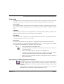
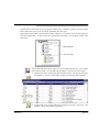
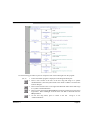
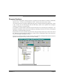
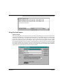
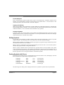
Project Workspace
The project workspace displays the project as a hierarchical tree structure showing
related PLC and program details. Select the Toggle Project Workspace button from
the toolbar to activate this view. Deselect the Toggle Project Workspace button from
the toolbar to deactivate this view.
Revision 2.1
Page 14
OMRON
CHAPTER 2 – Quick Start Guide
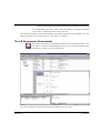
A description of each object in the hierarchy and their associated context menus is provided as follows:
PLC. Refer to the CX-Server PLC Tools User Manual for details.
Global Symbol Table. Refer to Chapter –2 Introducing Symbols and the Symbol Table
for details.
IO Table. Refer to the CX-Server PLC Tools User Manual for details.
PLC Settings. Refer to the CX-Server PLC Tools User Manual for details.
Memory Card. Refer to the CX-Server PLC Tools User Manual for details. The
Memory Card object can only be selected when the PLC is on-line.
Error Log. Refer to the CX-Server PLC Tools User Manual for details. The Error Log
object can only be selected when the PLC is on-line.
PLC Memory. Refer to the CX-Server PLC Tools User Manual for details.
Program. Refer to Chapter –2 Using CX-Programme for details.
Local Symbol Table. Refer to Chapter –2 Introducing Symbols and the Symbol Table
for details.
Sections. Refer to Chapter – 2 Program Sections.
Collapse/Expand. The hierarchy can be collapsed or expanded to show either a partial
view or full view of the project workspace tree.
Revision 2.1
Page 15
OMRON
CHAPTER 2 – Quick Start Guide
Diagram Workspace
The Diagram Workspace can display a Ladder program, the symbol table of that program or the
Mnemonics view. The details displayed depend upon the selection made in the project workspace.
When a new project is created or a new PLC added to a project, an empty Ladder program is
automatically displayed on the right-hand side to the project workspace. The symbol table and
Mnemonics view must be explicitly selected to be displayed. All views can be opened at the same time
and can be selected via options associated with the Window menu.
The Ladder program graphically represents the PLC power flow from left to right and the program
sequence from top to bottom.
PLC program instructions can be entered as a graphical representation in Ladder form. Programs can
be created, edited and monitored in this view.
Follow the examples provided to develop an understanding of the Diagram Workspace.
Select the View Diagram button from the toolbar. The Ladder program window is
displayed in the Diagram Workspace.
Revision 2.1
Page 16
OMRON
CHAPTER 2 – Quick Start Guide
The following items are standard features of the Ladder program area:
♦
Cursor. A rectangular block showing the current position within the rung. The location of the
cursor is displayed in the status bar.
♦
Rung. A logical unit of a ladder program. A rung can encompass one or more rows and columns.
All rungs are numbered.
♦
Bus-bars. The left bus-bar provides a graphical representation of the power supply bus-bar. The
right bus-bar contains the output region: to align objects to the right bus-bar. The right bus-bar is
selectable for display. If shown, the ladder rungs are justified so that the outputs of the rungs are
organised along it.
♦
Grid Dots. Dots that display at the connection points of each cell. To display the grid, select the
Grid button from the toolbar.
♦
Rung Margin Area. The area to the left of the Left bus-bar. The rung number and step number for
each rung are shown here (rung number on the left).
♦
Automatic Error Detection. A bar is displayed to the left of the currently selected rung area. As
elements and instructions are added to the rung, the additions are automatically checked to see if
they are valid. The colour of the bar indicates the validity of the program: red highlights an error,
whilst green indicates a correct entry. In addition, elements of the text on the ladder are drawn in
this error colour if a problem exists.
The colour and display preferences of the above features can be amended by selecting Options from the
Tools menu.
More than one element in a rung can be selected by pressing the mouse button down on an element and,
keeping the left-mouse button depressed, dragging a highlight over other elements in the rung. Selected
elements can then be moved as a block.
Mnemonics View
The Mnemonics view is a formatted editor for programming in mnemonic instructions. This view is
made up of a table of six columns containing the rung number, step number, instruction, operands, value
and comment.
Mnemonic instructions are a ‘low-level’ view of a PLC program, whilst ladder is higher. Since the ladder
program is just a higher level representation of the mnemonic instructions, it is possible to type in
mnemonics and see the ladder program update.
Select the View Mnemonics button from the toolbar. The Mnemonics view is
displayed in the Diagram Workspace.
Revision 2.1
Page 17
OMRON
CHAPTER 2 – Quick Start Guide
1, 2, 3…
1.
To program in mnemonics, open the mnemonic view and place the cursor on the
desired instruction.
2.
Press ENTER – this will enter the editing mode.
3.
Edit or type the new instruction lines. A mnemonic instruction consists of an
instruction name followed by a set of operands separated by spaces (e.g. ‘MOV
#1 A2’).
4.
Either press ENTER to move to the next line, or press ‘down’ or ‘up’ on the
keyboard to move to another line – the updated line is still kept.
The newly entered information is separated out over the columns in the table.
5.
When finished with editing, press ‘Esc’ to come out of editing mode.
Whilst entering a program in the mnemonics view, the ladder view shows the instructions in the new rung
as statement list. Once enough instructions have been entered to enable its drawing in ladder format it
is redrawn.
Instructions can be transferred to and from the Mnemonics view using the standard Microsoft Windows
Cut or Copy and paste functions. For example, it is possible to paste a large amount of program from
a text editor. Refer to Chapter 3 - Project Reference for further information.
Introducing Symbols and the Symbol Table
PLC addresses, which are used as operands in a PLC program, can be assigned a symbolic name and/or
a comment for the purpose of reference during programming. An address with a name or comment is
known as a Symbol.
A symbol table is an editable list of symbol definitions – the names, addresses and comments. This list
also provides information on the following:
♦
Rack location. If the address is contained within the PLC IO table, this shows the address’ rack
location.
♦
Usage. If the address is contained within the PLC IO table, this shows the physical hardware type
(i.e. ‘Input’ or ‘Output’) which is mapped to the address. If no hardware is mapped, ‘Work’ is
shown, meaning that the symbol is for general use.
Revision 2.1
Page 18
OMRON
CHAPTER 2 – Quick Start Guide
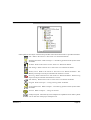
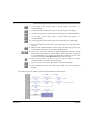
It is possible to indicate the physical format of the data that is stored at an address. This additional data
typing facility enables CX-Programmer to check whether the address is used consistently within
programs. In the symbol tables, an icon is shown next to a symbol that indicates its data type. The Data
Type set is as follows:
Data Type
BOOL
Data Type Description
DINT
Address of a binary bit - a logical Boolean on or off state. This type is
typically used for contacts or coils.
This is a special data type, for backward compatibility. It is an address (nonbit) to data of any type (unsigned or signed, one or more words), so can be
used in place of any of the above data-types except NUMBER and BOOL.
The data type is weak, and so checking is limited (e.g. CX-Programmer
cannot check if the address is being used for BCD or binary values).
Address of a signed, double binary word.
INT
Address of a signed, single binary word.
LINT
Address of a signed, quad binary word.
NUMBER
A literal numeric value - not an address. The value can be signed, or floating
point. NUMBERs are used for any literal value or for timer/counter identifiers
(for TIM/CNT, only unsigned integer values are allowed).
Floating point values are only suitable within IEEE REAL type operands.
CHANNEL
Icon
Note: When used as BCD number operands, the value is treated as if it
were entered in decimal with a ‘#’ on the front. E.g. using a NUMBER ‘1234’
is equivalent to typing ‘#1234’ as the operand, so that the decimal
interpretation is made of the value.
The value of a NUMBER data type is assumed to be decimal, unless it is
prefixed with '#' for a hexadecimal value.
REAL
LREAL
Note: NUMBERs entered in hexadecimal are converted to decimal for BCD
operands (e.g. a NUMBER defined as ‘#10’ will appear as ‘#16’ for a BCD
operand).
Address of a double word floating point value (IEEE format - use the UDINT
type for the BCD, FDIV format).
Address of a long word floating point value (IEEE format - use the ULINT
type for the BCD format).
UDINT
Address of an unsigned, double binary word.
UDINT_BCD
Address of an unsigned, double BCD word.
UINT
Address of an unsigned, single binary word.
UINT_BCD
Address of an unsigned, single BCD word
ULINT
Address of an unsigned, quad binary word.
ULINT_BCD
Address of an unsigned, quad BCD word.
Each program within a PLC has a ‘local’ symbol table that consists of symbols that are for use
specifically in that program. Each PLC within a project has a ‘global’ symbol table that consists of
Revision 2.1
Page 19
OMRON
CHAPTER 2 – Quick Start Guide
symbols that can be used in any of its programs. When a PLC is added to a project, its global symbol
table is filled with a pre-set list of symbols, dependant upon PLC type.
Each symbol name must be unique within its table. However, it is possible to use the same name in a
local and a global table – in this case, the local symbol takes precedence over the global symbol of the
same name.
The symbol table allows these names to be entered and edited directly. Each symbol
name must be unique. Use the following procedure to activate the symbol tables.
1, 2, 3…
Revision 2.1
1.
Double-click on the symbol table object beneath the PLC in the project workspace.
The global (i.e. PLC’s) symbol table is displayed containing global symbols.
2.
Double-click on the symbol table object beneath a program in the project. The
program’s local symbol table is displayed.
Page 20
OMRON
CHAPTER 2 – Quick Start Guide
Using CX-Programmer
This chapter contains an example tutorial and also describes basic procedures which
should be considered before performing any programming task on the computer and
preparing ladder programs with CX-Programmer, and how to use the various tools to
improve productivity. CX-Programmer offers many methods of working with its tools:
in general, instructions are given for using the toolbar icon in the first instance.
The following tutorial has been based on a CS1H PLC. The choice of PLC made here affects a number
of other parameters that may need to be set up. For example, the CV-series requires setting up the IO
table, and using the Settings object in the Project hierarchy to establish specific PLC characteristics.
When planning a PLC programming project, various items need to be considered and set up within CXProgrammer before beginning to lay down program instructions. For example, it is important for CXProgrammer to know the model and configuration of the PLC to be programmed, so that it can establish
the correct program checking and communications for that PLC. Programming should be targeted at the
PLC that is to be used. It is possible to change the PLC type at any time - the program(s) are then
converted. However, since the conversion may not be perfect, it is best to set the correct PLC type at the
beginning.
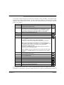
Before programming, it is recommended that a checklist of the important program
aspects be constructed, including its structure and PLC parameters. To start a new
project in CX-Programmer, follow these steps in addition to the basic procedure
outlined in your PLC programming manual:
Revision 2.1
Page 21
OMRON
CHAPTER 2 – Quick Start Guide
Step
Determine PLC essential parameters
Determine allocation of PLC memory
Determine PLC setup parameters
Create appropriate IO Table
Decide how to input and edit the program
Include
PLC series, PLC type, CPU (where applicable),
communications interface, choice of editor and project type.
Where applicable. For example, C-series PLCs require
working out the balance required between program memory
and expansion data memory.
PLC configuration data.
List all related IO devices and addresses. Some C-series
PLCs do not support this function.
CX-Programmer offers two languages: ladder and mnemonic.
A mixture may be used.
Starting a New Project
Once the project requirements have been worked out on paper, the first step is to create a project and
define the device entries for that project. A project can have multiple PLCs. CS1-series PLCs are multitasking and can therefore have more than one program associated with them in the project; CV-series
PLCs and C-series PLCs can only have one program associated with the device.
Use the following procedure to create a new project.
1, 2, 3…
1.
Select the New button from the toolbar.
2.
Define the device entries for the project. Refer to the CX-Server PLC Tools User
Manual for further information. For this tutorial, set the PLC type as CS1G with
CPU type CPU42.
3.
Save the project. Select the Save Project button from the toolbar. The Save CXProgrammer File dialogue is displayed.
4.
Type a valid file name in the File Name field. Select the Save pushbutton to save
the new project. Select the Cancel pushbutton to abort the operation.
When a new PLC is added to a project, the following empty tables are created:
♦ Empty local symbol table;
♦ Global symbol table containing pre-set symbols;
♦ IO Table;
♦ PLC Memory data;
♦ PLC Settings data.
The project workspace is populated with the contents of the newly created project and a Ladder program
is displayed in the Diagram Workspace ready for programming to begin.
A description of each object in the project hierarchy is provided in Chapter 4 - Reference.
Within the Ladder program, the current position is indicated by a highlighted rectangular block, known
as the cursor. Using the mouse or the arrow keys, the cursor can be positioned at any point within the
diagram. An element can be placed at the current cursor position by either selecting it from the Insert
menu, selecting it from the toolbar or by pressing its assigned shortcut key. An element can be placed
in any empty grid position, or may overwrite a horizontal element.
Revision 2.1
Page 22
OMRON
CHAPTER 2 – Quick Start Guide
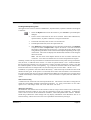
Task and program types depend on the PLC type, defined in the program properties.
Use the following procedure to change properties for a program at any time.
1, 2, 3…
Note:
1.
Click on the Program object in the project workspace.
2.
Select the Show Properties button from the toolbar. The Program Properties
dialogue is displayed.
3.
Select a Task type setting from the Task Type field. Since this program is written
for a cyclic task, set this to ‘Cyclic Task 00’. The icon to the left of the program
name changes to reflect the task type, and the task number is shown on the right of
the program name.
4.
Set the Operation Start setting so the program starts on PLC start-up.
Programs that have their tasks assignment set to “unassigned” are effectively excluded
from the project. This means that the program will not be compiled or downloaded to
the PLC.
Writing a Ladder Program
The following program sequences a set of traffic lights. The sequence is a standard
British sequence of the following order:
•
Red light only;
•
Red and Amber lights together;
•
Green light only;
• Amber light only.
Writing a ladder program consists of:
•
Creating symbols;
•
Creating the ladder program;
•
Compiling (automatically checking) the program;
•
Transferring the program to and from a PLC;
•
Comparing the program with the PLC program;
•
Monitoring the program during execution;
•
Performing an on-line edit (if necessary).
Creating Symbols
An important step in creating a Ladder Program is the definition of those PLC data areas that are to be
referenced by the program. It is possible to skip this step, and use addresses directly within the program.
It is better, however, to create symbolic names for the addresses so that the programs become more
readable and maintainable.
Revision 2.1
Page 23
OMRON
CHAPTER 2 – Quick Start Guide
Use the following procedure to create symbols.
1, 2, 3…
1.
Click in the Diagram Window and select the View Local Symbols button from the
toolbar.
2.
Select the New Symbol button from the toolbar. The Insert Symbol dialogue is
displayed.
3.
Enter ‘AmberLight’ in the Name field.
4.
Set the Address or value field to ’10.01’.
5.
Leave the Data type field set to ‘BOOL’ to indicate a bit (binary) value.
6.
Type ‘Prepare to go / stop’ in the Comment field.
7.
Select the OK pushbutton to proceed.
Repeat this procedure for each of the other entries in the following table:
Name
Data Type
Comment
RedLight
10.00
BOOL
Stop.
GreenLight
10.02
BOOL
Go.
RedLightTimer
1
NUMBER
Timer for the red light period.
AmberLightTimer
2
NUMBER
Timer for the amber light period.
GreenLightTimer
3
NUMBER
Timer for the green light period.
AmberOnlyTimer
4
NUMBER
Timer for the amber only period.
RedTimerDone
T0001
BOOL
AmberTimerDone
T0002
BOOL
GreenTimerDone
T0003
BOOL
AmberOnlyTimerDone
T0004
BOOL
48
NUMBER
TimeInterval
Revision 2.1
Address
Speed at which the sequence works (ticks).
Note:
It is important to use the standard form of addresses in CX-Programmer. Depending
upon their defined type, addresses may have two components – a channel and a bit
number. In the above example, the symbol ‘RedLight’ is defined as type ‘BOOL’.
Entering the address ‘10’ is interpreted by CX-Programmer as ‘0.10’. If it had been
intended as bit zero at address 50, it would have been necessary to enter it as ‘5000’
or (more easily) ‘50.00’.
Note:
Symbols of NUMBER type have been used to indicate the timer numbers used in the
PLC. Whilst it is possible to type numbers directly into the program ‘TIM’ instruction
operands, it is more readable to define symbols which can have a name and comment.
CX-Programmer allows numbers to be defined as symbols, as well as addresses.
Page 24
OMRON
CHAPTER 2 – Quick Start Guide
Note:
It is possible to create symbols whilst creating the PLC programs – when entering
ladder contact/coil and instruction information. It is not necessary to use the symbol
table to create symbols.
Creating a Ladder Program
A PLC can be programmed using either the Ladder or Mnemonic programming languages. The Ladder
program is created in the Diagram View of the Diagram Window.
Use the following procedure to create a ladder program.
1, 2, 3…
1.
Ensure the Ladder program is displayed in the Diagram Workspace.
2.
Give the rung a comment by using the Properties box (move the cursor to the rung
margin and access the properties box from the context menu.
Note: A rung comment placeholder can be inserted into the compiled code (if the
Include Comment Instructions property of the PLC is set), and the comment
itself can then be saved to a file or file-card. All comments are saved in the project
file.
3.
Place a New Closed Contact at the start of the rung – select the New Closed
Contact button from the toolbar and click in the top left cell. The New Closed
Contact dialogue is displayed.
4.
Select ‘AmberOnlyTimerDone’ from the Name or Address list field and select
the OK pushbutton.
Note that the rung margin now shows a red mark down its side. This is to
indicate that the rung is incomplete – the marker bar shows whenever the rung
has an error.
5.
Place an Instruction by selecting the New PLC Instruction button from the toolbar
and clicking next to the Contact. The New Instruction dialogue is displayed.
6.
Enter the instruction ‘TIM’ and the two operands to ‘RedLightTimer’ and
‘TimeInterval’, in the Operands field.
Note: The value of the symbol ‘RedLightTimer’ is used for the operand – the
number ‘1’. In CX-Programmer, it is necessary to use a NUMBER for the first
operand of a TIM/CNT instruction. It is not allowed to use a timer/counter
address (i.e. T001 is not allowed).
Revision 2.1
7.
Select the OK pushbutton to accept the settings in the New Instruction dialogue.
Note that the rung margin no longer shows a red mark down its side. There is no
error within the rung.
8.
Give the instruction a comment by using the Properties box (place the cursor over
the instruction title and bring up the properties). Enter the text ‘Red light on only’
and press return.
Page 25
OMRON
CHAPTER 2 – Quick Start Guide
9.
Place a New Contact at the start of the next rung. (Either like before, or by moving
the cursor to the start of the rung and using the Insert/Contact/Normally Open
menu command, or by pressing the shortcut key displayed for that menu command
– usually ‘C’). The New Contact dialogue is displayed.
10. Select ‘RedTimerDone’ from the Name or Address field and select the OK
pushbutton.
12. Place an instruction next to the Contact and display the New Instruction dialogue.
(Either like before, or by using the Insert/Instruction menu command, or by
pressing the shortcut key for that command – usually ‘I’). Enter the instruction
‘TIM’ in the Instruction edit box. Enter the two operands ‘AmberLightTimer’ and
‘TimeInterval’ in the Operands field.
13. Select the OK pushbutton to accept the settings in the New Instruction dialogue.
14. Give the instruction a comment of ‘Red and amber lights on together’.
15. Place a New Contact at the start of the next rung to display the New Contact
dialogue.
16. Select ‘AmberTimerDone’ from the Name or value field and select the OK
pushbutton.
17. Place an instruction next to the Contact and display the New Instruction dialogue.
Enter the instruction ‘TIM’ and the two operands ‘GreenLightTimer’ and
‘TimeInterval’ in the Operands field.
18. Select the OK pushbutton to accept the settings in the New Instruction dialogue.
19. Give the instruction the comment ‘Green light on only’.
20. Place a New Contact at the start of the next rung to display the New Contact
dialogue.
21. Select ‘GreenTimerDone’ from the Name or value field and select the OK
pushbutton.
22. Place an instruction next to the Contact and display the New Instruction dialogue.
Enter the instruction ’TIM’ and the two operands ‘AmberOnlyTimer’ and
‘TimeInterval’ in the Operands field.
23. Select the OK pushbutton to accept the settings in the New Instruction dialogue.
24. Give the instruction a comment of ‘Amber light on only’.
The Ladder Program should resemble that illustrated (depending upon the display options chosen).
Revision 2.1
Page 26
OMRON
CHAPTER 2 – Quick Start Guide
Use the following procedure to place an output for each of the traffic lights into the program.
1, 2, 3…
Revision 2.1
1.
Ensure the Ladder program is displayed in the Diagram Workspace.
2.
Place a New Contact at the start of the next rung and assign it to symbol
‘RedTimerDone’ (select the symbol name in the ‘Name or address’ list of the New
Contact dialogue.
3.
Place a New Closed Contact to the right of the Red and Amber Timer and assign
it to symbol ‘GreenTimerDone’.
4.
Place a Coil by selecting the New Coil button from the toolbar next to the Green
Light Timer. Select ‘RedLight’ from the Name and Address field and select the
OK pushbutton.
5.
On the next rung below, place a contact to the left.
‘AmberTimerDone’.
Assign it to use
Page 27
OMRON
CHAPTER 2 – Quick Start Guide
6.
To the right of the contact, place a closed contact, and assign it to
‘GreenTimerDone’.
7.
To the right of the second contact, place a coil and assign it to ‘RedLight’.
8.
On the next rung, place a contact on the left, and assign it to ‘AmberTimerDone’.
9.
To the right of the contact, place a closed contact and assign it to
‘GreenTimerDone’.
10. To the right of the second contact, place a coil and assign it to ‘AmberLight’.
11. Press return when the selected cell is on the right of the rung. This will create a
new line.
12. Below the left ‘AmberTimerDone’ contact (but on the same rung), place a New
Closed Contact and assign it to the symbol ‘RedTimerDone’.
13. Place a new Vertical by selecting the New Vertical button from the toolbar
between the ‘GreenTimerDone’ Contact and the ‘AmberLight’ Coil. Connect this
to the ‘RedTimerDone’ by placing New Horizontal connections to join to the
Vertical by selecting the New Horizontal button from the toolbar.
14. Place a New Contact at the start of the next rung and assign it to symbol
‘GreenTimerDone’ via the New Contact dialogue.
9.
Place a Coil next to the contact and assign it to symbol ‘GreenLight’.
10. Place an Instruction on the next rung of type ‘END’ via the New Instruction
dialogue.
The output rungs of the Ladder program should resemble those shown below.
Revision 2.1
Page 28
OMRON
CHAPTER 2 – Quick Start Guide
Use the following procedure to examine the ladder program.
1, 2, 3…
1.
Ensure the Ladder program is displayed in the Diagram Workspace.
2.
Switch to symbol table by selecting the View Local Symbols button from the
toolbar. Open the Address Reference Tool by selecting the Show Address
Reference Tool button from the toolbar.
3.
Examine each symbol’s usage in the program by selecting a symbol whilst
displaying the Address Reference Tool, or moving around the diagram with the
cursor.
The Ladder Program can also be viewed and edited in Mnemonics view. Block Programs can be entered
in either Mnemonics view or by showing a rung in statement list within the ladder editor..
Select the View Mnemonics button from the toolbar to display the Mnemonics view.
To enter mnemonics directly into the ladder editor, select View as Statement List for
the relevant rung.
Compiling the Program
The program undergoes continual verification during its creation and any subsequent editing; this applies
to both on-line and offline programming. Errors appear in red in the ladder diagram. If a rung contains
an error, a red line appears down the left-hand side of the Ladder rung. This can happen, for example,
when has element has been placed on the diagram window but has not been assigned a symbol or address.
Use the following procedure to compile the program.
1, 2, 3…
1.
To list any errors in the program, click the right-mouse button and select the
Compile Program button from the toolbar. The output (for example, compilation
progress or error details) is displayed in the Compile tab of the Output Window.
Downloading the Program to a PLC
The project contains details of the type and model of the PLC for which the program is intended. Before
a program can be downloaded, this information should be reviewed to ensure that it is correct and that
it matches the PLC actually being used. The appropriate communications interface type should also be
selected for the connected PLC. Other parameters, for example PLC Setup may need to be specified
before connecting to the PLC and running a program. Refer to Chapter 4 - Reference and to the CXServer PLC Tools User Manual concerning the definition of the project’s IO Table, PLC Settings,
Memory Card and Error Log.
Use the following procedure to transfer the program to the PLC.
1, 2, 3…
Revision 2.1
1.
Save the current project by selecting the Save Project button from the toolbar. If
the project has not been saved before, the Save CX-Programmer File dialogue is
displayed. Enter a file name in the File name field and select the Save pushbutton
to complete the save operation.
Page 29
OMRON
CHAPTER 2 – Quick Start Guide
2.
Connect to the PLC by selecting the Work On-line button from the toolbar. A
confirmation dialogue is displayed: select the Yes pushbutton to connect. Since
ordinary editing is not allowed when on-line, the program becomes greyed.
3.
Select the program object in the project workspace.
4.
Set the PLC operating mode to Program by selecting the Program Mode button
from the toolbar. If this step is ignored, CX-Programmer automatically places the
PLC in this mode.
5.
Select the Download button from the toolbar. The Download Options dialogue is
displayed.
6.
Set the Programs field and select the OK pushbutton.
Uploading the Program from a PLC
Use the following procedure to transfer the program from the PLC.
1, 2, 3…
1.
Select the PLC object in the project workspace.
2.
Select the Upload button from the toolbar. The first program in the project tree is
compiled. If the PLC is offline, a confirmation dialogue is displayed: Select the
Yes pushbutton to connect to the PLC. The Upload Options dialogue is displayed.
3.
Set the Programs field and select the OK pushbutton.
Comparing the Project Program/s with the PLC Program/s
A project program can be compared with the program in the PLC. Use the following procedure to
compare the project program and the program on the PLC.
1, 2, 3…
1.
Select the PLC object in the project workspace.
2.
Select the Compare with PLC button from the toolbar. The Compare Options
dialogue is displayed.
3.
Set the Programs field and select the OK pushbutton. The Compare dialogue is
displayed.
Details regarding comparisons between computer and PLC programs are displayed in the Compile tab
of the Output Window.
Revision 2.1
Page 30
OMRON
CHAPTER 2 – Quick Start Guide
Monitoring a Program During Execution
Once the program has been downloaded, it can be monitored in the Diagram Workspace (which acts a
mimic display) during execution. Use the following procedure to monitor the program.
1, 2, 3…
1.
Select the PLC object the project workspace.
2.
Select the Toggle PLC Monitoring button from the toolbar.
3.
As the program executes, data and power-flow can be followed in the Ladder
program; for example, connections are selected and values are incremented.
Note:
Individual PLC data elements can be monitored via the Watch Window. This window
allows monitoring of addresses from multiple PLCs at the same time.
Note:
The values are monitored in a format according to the data-type of the symbol which
is being used for the operand, or the data-type of the instruction operand itself. To
always monitor in a single, hexadecimal format, turn on the Monitor In Hex option
from the toolbar.
On-line Edit
Although the downloaded program has been greyed to prevent direct editing, the Ladder program can
be amended by explicitly selecting the On-line Edit feature.
It is usual to have the PLC operating in Monitor mode while using on-line editing functions. On-line
editing is not possible in Run mode.
Use the following procedure to edit the program on-line.
1, 2, 3…
Revision 2.1
1.
Select the rungs to be edited by dragging the mouse and selecting the required
rungs.
Page 31
OMRON
CHAPTER 2 – Quick Start Guide
Note:
2.
Select the Compare with PLC button from the toolbar to ensure that the edited
area is the same as in the PLC.
3.
Select the On-line Edit Rungs button from the toolbar. The background to the
rung changes to show that it is now an editable area. The rungs outside this area
cannot be altered but elements can be copied from these rungs into the editable
rungs.
4.
Edit the rungs as appropriate.
5.
When satisfied with the results, select the Send On-line edit Changes button from
the toolbar. The editing is checked and transferred to the PLC.
6.
Once these changes have been ‘sent’ to the PLC, the editable area becomes readonly once more. The on-line edit can be cancelled at any point prior to committing
the changes by selecting the Cancel On-line Edit button from the toolbar.
A symbol address or type cannot be edited on-line.
Attaching Comments
An attached comment is a comment associated with an element of a program (i.e. contact, coil or
instruction). The comment is entered through the Properties dialogue box of the element by selecting
the Properties option from the context menu of the item.
When a comment has been entered against an element, a circle will appear at the top-right corner of the
element. This circle contains a number that uniquely identifies the comment within the rung. The
comment itself will appear to the right of the circle for output instructions (subject to the chosen ladderinformation options), or it will appear in the Rung’s Annotation List.
Summary
In this chapter, the programmer has been introduced to the following concepts:
Revision 2.1
•
Starting the CX-Programmer application.
•
CX-Programmer and projects. The CX-Programmer environment, including the
project workspace, Diagram Workspace, Mnemonics view and symbol tables.
•
Getting started with CX-Programmer.
•
Setting up a Ladder program.
•
Writing a Ladder program.
Page 32
OMRON
CHAPTER 3 – Project Reference
CHAPTER 3
Project Reference
This chapter describes the different views available; the features common to the objects displayed in the
Project Window and standard Microsoft Windows procedures that are also common to these components.
Project Workspace
The project workspace displays the project as a hierarchical tree structure showing
related PLC and program details. Select the Toggle Project Workspace button from
the toolbar to display the project workspace and remove the project workspace from the
display.
\
A description of each object in the Project Tree Workspace and their associated context sensitive menus
is provided in Chapter 4 - Reference.
Double clicking on an object opens it either in the Diagram Workspace or in a new window. Selecting
an object and clicking the right-mouse button displays the associated context sensitive menu.
The hierarchy can be collapsed or expanded to show either a partial view or full view
of the project tree.
More than one Ladder Diagram symbol table or Mnemonics View can be displayed. Select the
appropriate window from the list of open windows from the Window menu.
Revision 2.1
Page 33
OMRON
CHAPTER 3 – Project Reference
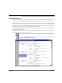
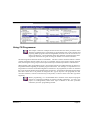
Program Sections
For the easier management of large programs, a program can be divided into a number of definable,
named sections. A section is like a chapter in a book – the PLC scans the sections in order.
A list of the sections in a program is displayed in the project workspace under the program name. There
is also a section list view showing the Start and End steps, which can be opened in the workspace
window by clicking on a program name.
It is possible to reorder and/or rename the sections from this list or from the project workspace. It is
important to remember however that when reordering or deleting sections the last section in the program
must always contain the 'END' instruction.
Program sections can be reordered using the mouse to drag and drop sections up or down in the section
list. When using the keyboard, the 'Move Up' or 'Move Down' commands from the context menu of a
section on the project workspace are used.
Sections in a specific program can also be used to store frequently used algorithms which can then be
copied to other programs, using a section as a kind of library.
Revision 2.1
Page 34
OMRON
CHAPTER 3 – Project Reference
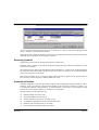
Use the following procedures to insert, rename, move or delete a section in a program.
1, 2, 3…
1.
Inserting a new program section
(a) Select the program name in the Project tree.
(b) Click the Insert pushbutton in the toolbar or from the Insert menu select
Section. The new section will be added to the bottom of the section list
Note that if previous sections have been renamed the new section will be
named Section1, if not, it will be given the next section number. If the new
section is to be the last in the program it must include the ‘END’ instruction.
2.
Renaming a program section
(a) Select the section to be renamed and click the right mouse button. From the
context menu select Properties.
(b) In the Properties dialogue enter the new name for the section and then close
the dialogue. The new section name will be displayed in the section list.
Note that spaces used in the new name will be translated into underscores
when displayed in the section list.
3.
Moving a program section
(a) Select the program section to be moved, and from the Edit menu select Cut.
Move to the location of the program (the program item on the project
workspace) for the section to be placed, and select Paste from the Edit menu.
then using the mouse drag and drop the section in the appropriate position in
the section list.
(b) Instead of using the Edit commands, it is possible to drag and drop the section.
Drag the section to the program item where it is required.
Note that when the section is dropped, it will reposition its self immediately below
the cursor. To drag a section to the top of the list, it must be dropped on the
program item itself.
A section may be moved to another program, or just within the same program, in
which case it changes the execution sequence of the sections.
(b) When using the keyboard the 'Move Up' or 'Move Down' commands from the
context menu of a section in the project workspace are used. Each command
will move the selected section up or down one position at a time.
4.
Copying a program section
(a) Select the section to be copied, and from the Edit menu select Copy. Move
to the location of the program (the program item on the project workspace) for
the copy to be placed, and select Paste from the edit menu.
Revision 2.1
Page 35
OMRON
CHAPTER 3 – Project Reference
(b) Instead of using the Edit commands, it is possible to drag and drop the section
in a similar way to moving it. However, if the ‘Ctrl’ key is held down before
dropping the section (on the program item), then a copy operation will take
place.
5.
Replacing a program section
(a) To replace a section, copy or move the required section on top of the one to
be replaced. A confirmation is then requested.
6.
Deleting a program section
(a) Select the section to be deleted, and from the Edit menu select Delete.
When using the Copy and Paste commands with program sections only the contents of a section are
copied, not the section itself. In order to duplicate a section a new section must first be created then the
contents of the selected section can be copied and pasted into it.
Downloading / Uploading
CX-Programmer can also use a PLC instruction to store the section markers in the PLC when the
program is downloaded. This will allow CX-Programmer to upload a single section for online-editing.
It will also allow CX-Programmer to upload the program complete with section breaks.
A single program section may be uploaded for online-editing (reducing the transfer time to a minimum).
However, it may not be downloaded since it is only a program segment. To download a program section,
it is necessary to copy it into a complete program.
Cross-Reference Report
The Cross-Reference Report allows the symbol usage within different memory areas to be examined. It
can be used for checking the values being set by instructions when the program is not behaving as
expected. It can also allow the programmer to make efficient use of memory resources.
Revision 2.1
Page 36
OMRON
CHAPTER 3 – Project Reference
Use the following procedure to generate a cross-reference report.
1, 2, 3…
1.
Select the Cross-Reference Report button from the toolbar to open the CrossReference Report.
2.
Select a usage from the Report type field, either Detailed Usage, Usage Overview
or Usage Overview Including Unused.
3.
Select an area from the Memory Area field. When changing options, reselect from
the Memory Area field to refresh the report.
4.
Select the Generate pushbutton to activate the report. In addition to the address
report information, the amount of free program memory in the PLC is displayed
in the Free UM field. The total program memory size of the PLC is displayed in
the Total UM field.
The Detailed Usage option within the Report type field displays information about the usage of any
address used within the PLC program(s). The program name, step number, instruction type, the start
address of the operand and symbol details relating to each usage are shown.
The Usage Overview option within the Report type field displays an overall summary of the usage for
the selected memory area, showing only the addresses that are in use. For each used address, a usage
count is displayed. The ‘D’ symbol denotes that the address has a symbol assigned to it.
The Usage Overview Including Unused option within the Report type field displays the usage overview
of the memory area, including addresses that are not used.
A cross-reference report can be printed. Use the following procedure to print a cross-reference report.
1, 2, 3…
1.
Select the Cross-Reference Report button from the toolbar to open the CrossReference Report.
2.
Generate an appropriate cross-reference report.
3.
Select the Print pushbutton. A standard Microsoft Windows Print dialogue defines
printer settings and allows print parameters to be entered.
Address Reference Tool
The Address Reference Tool shows how and where a PLC address is used within the program set of a
PLC.
Revision 2.1
Page 37
OMRON
CHAPTER 3 – Project Reference
Use the following procedure to use the Address Reference Tool.
1, 2, 3…
1.
Open a Ladder program by double-clicking the program object in the project
workspace.
2.
Select a cell in the Ladder program.
3.
Select the Address Reference Tool button from the toolbar. The Address
Reference Tool window is displayed in the Diagram Workspace. The Address
Reference Tool displays a list of references made to the address selected in the
Ladder program.
4.
With the Address Reference Tool still open, another selection can be made in the
Ladder program; the Address Reference Tool is refreshed accordingly.
The Address Reference Tool is displayed in front of other windows. Only one Address Reference Tool
can be opened at a time. The window can be ‘docked’ within the main CX-Programmer window.
Note:
Revision 2.1
It may be necessary to show the address reference tool in order to use the commands
Go to Next Output, Go to Next Input and Go to Next Address Reference,
depending upon the diagram options chosen (see page 44).
Page 38
OMRON
CHAPTER 3 – Project Reference
Output Window
The Output window is usually displayed at the foot of the main window. Select the
Toggle Output Window button from the toolbar to display the Output window. Select
the Toggle Output Window button from the toolbar to remove the Output window
from the display.
The Output Window has three different views:
♦
Compile. The Compile tab displays the output produced from program compilation. Selecting an
error highlights the source of the problem in the Ladder Diagram. The Compile tab also displays
other information, for example, warnings and connection messages.
♦
Find Report. The Find Report tab displays the output produced from a search of project files for a
particular entry. Refer to Chapter – 3 Finding and Replacing
♦
Transfer. The Transfer tab view displays the results of file or program loading.
To clear the view, select Clear from the context sensitive menu.
To go to the source of errors indicated in the Compile or Find Report tabs, double-click the message in
the output window. It is also possible to use the Next Reference command from the Edit menu – this
jumps to the location of the next message on the output window, whichever tab is on show. The location
jumped to is highlighted in the Diagram Workspace. Note that is possible to quickly move through the
location of the messages by continually using the Next Reference command.
Watch Window
The Watch window allows the contents of specified PLC addresses in more than one PLC to be
monitored at the same time. The Watch window is usually displayed at the foot of the main window. It
displays the value of the contents of PLC memory during program execution. The watch window also
supports drag and drop enabling elements from the ladder view or the symbol table to be dropped on to
the watch window. Watched items may also be added via a dialog box.
Revision 2.1
Page 39
OMRON
CHAPTER 3 – Project Reference
Use the following procedure to use the Watch window.
1, 2, 3…
1.
Open the Watch window by selecting the Toggle Watch Window button from
the toolbar View – Windows option.
2.
Select Add from the context sensitive menu. The Add Watch dialogue is
displayed.
3.
Select the PLC from the PLC field and the name, address or symbol to be
monitored in the Name and Address field. Select the Browse pushbutton to locate
a symbol, if required.
Note that it is also possible to select how the information is viewed inside the
address by choosing the data type of the information. A local symbol may be
entered by typing in the program and symbol name, separated by a '.' character
(this symbol 'path' is also shown in the watch window for local symbols).
4.
Select how to view the data from the View As field.
5.
Select the OK pushbutton to complete the operation.
pushbutton to abort the operation.
Select the Cancel
The PLC name is added to the Watch window. During program execution, the changing value of this
address is displayed. Values can be set in this window to a specific value to test program execution.
When pause monitoring is taking place, items in the watch window are monitored as normal until the
trigger point is reached or the user triggers manually. At this time the monitoring is stopped and the
value field of all items within the watch window are cleared. When either monitoring or pause
monitoring is re-started, the value field of all the items within the watch window is refreshed with the
current value.
Dragging and Dropping Items
Symbols, ladder elements and symbol tables (from the project tree view) may be dragged and dropped
into the watch window. These items may be dragged individually or in block form. It is not possible to
drag elements into the watch window from the mnemonic editor, or entire sections from the project tree
view. Items may not be dragged from the watch window i.e. it is only a drag and drop target and not a
source.
It is not possible to view items that are of a Number type. Items that are of a Number type and are
dropped into the watch window will not be displayed and an error message for each item is displayed in
the transfer output window.
Revision 2.1
Page 40
OMRON
CHAPTER 3 – Project Reference
Pasting Items
Pasting items into the watch window is similar to the drag and drop mechanism. The items that may be
pasted are symbols, ladder elements and symbol tables (from the project tree view).
It is not possible to view items that are of a Number type. Items that are of a Number type and are pasted
into the watch window will not be displayed and an error message for each item in the transfer output
window.
Items cannot be cut or copied from the watch window.
Differential Monitoring
It is possible to initiate differential monitoring from the PLC | Monitor option or from the watch window
via a pop-up menu item,. This will display a dialog where the user may select the type of transition
trigger required for the currently selected item in the watch window. The dialog will then show a count
of how many times this transition has occurred until the user closes the dialog.
This facility is only available when the PLC for the currently selected item is in run or monitor mode.
Options and Preferences
A number of options and preferences can be set by selecting Options from the Tools menu.
Revision 2.1
Page 41
OMRON
CHAPTER 3 – Project Reference
Diagrams
The Diagrams tab allows settings to be applied to the Diagram Workspace upon entry to CXProgrammer.
Use the following procedure to change the settings applied to the Diagram Workspace.
1, 2, 3…
1.
Select the Diagrams tab within the Options dialogue.
2.
Set the Show rung and step numbers to view the rung and step numbers at the left
of the ladder display, in the rung margin. Deselecting gives a smaller rung margin.
3.
Setting the Show rung dividers will draw a line at the bottom of each rung, showing
its boundary.
4.
Setting the Show grid by default will place a dot pattern around each cell on the
ladder diagram. This pattern can aid element placement, but may be removed for
a clearer display.
5.
If the Show rung annotation lists is set then the list of comments which are within
the rung (both attached comments associated with particular elements within the
rung, and unattached comments) will be listed below the rung comment. Note that
this option can be quickly changed via the View Rung Annotations button on the
toolbar.
6.
If the Monitor in hex is set then the online monitoring format of values within PLC
addresses will always be shown in hexadecimal. This may be toggled from the
toolbar.
7.
Setting the Allow Address Referencing without Window option allows use of the
Go to Input, Go to Output, Go to Next Address Reference and Go to Previous
Jump Point commands when the address reference tool is not on show. If this
option is not set, then the tool must be visible to use these commands. Note that
when address referencing is active, a small delay may be experienced when
moving around a diagram, depending upon the size of the PLC program/s.
8.
View to show when split – enables two different views to be shown within the
editing window. It is possible to choose to see a part of the editing in mnemonic
mode and the other in ladder, or to see the local symbol table of the program in one
view.
9.
Setting the Show right bus-bar will show the right bus-bar with the ladder rungs
justified to fill the space between the left and right bus-bars. The output
instructions will appear aligned along the right bus-bar, as long as the rung can be
drawn within the number of cells to the right bus-bar. If the Expands to Widest
Rung option is chosen, then the right bus-bar position for a section is automatically
set to the widest rung in the program section. Note that this may result in slower
performance on a large section when editing or adding rungs, since if a rung is
expanded beyond the current width, the section will be reformatted.
If no right bus-bar is shown, the rungs are justified to the left, minimising space.
Revision 2.1
Page 42
OMRON
CHAPTER 3 – Project Reference
10. Select the OK pushbutton to apply the settings and close the dialogue. Select the
Apply pushbutton to change the settings but remain in the dialogue. Select the
Cancel pushbutton to abort the operation.
PLCs
The PLC tab provides a default PLC and CPU which appears when adding a new PLC to a project.
Use the following procedure to change PLC preferences.
1, 2, 3…
1.
Select the PLC tab within the Options dialogue.
2.
Set the Confirm all operations affecting the PLC setting to receive a confirmation
message for computer to PLC communications.
3.
Select the default PLC from the PLC Type field. When set CX-Programmer will
show a confirmation dialogue when an operation being carried out may affect the
running of a PLC.
4.
Select the default CPU from the CPU field. When a new PLC is created, these
details will be used to initialise it. A PLC type and CPU combination may be
selected, or the Use Current PLC button can be pressed, to set the details to that of
the currently selected PLC in the project.
5.
Set the Use Section marker instruction option to select whether, by default for a
new PLC, section divisions are to be downloaded or not. If set, an extra instruction
is hidden in the program for each section division. This allows upload options such
as the upload of a single section. It also allows the section structure to be retained
upon upload. If the option is turned off for a PLC, then the section structure will
not be downloaded, and upload will not retain the structure.
Note that this option can be enabled / disabled per PLC in the PLC properties
dialogue.
6.
The Use Comments instruction option determines, by default for a new PLC,
whether program comments (rung comments and annotations) are to include a
CMT instruction in the PLC. CMT instructions are used during upload so that
comments in a comment file can be linked back to the program properly. If this is
not set for a PLC then it is not possible to upload comments, but compiled
programs will be smaller since CMT instructions are not generated.
Note that certain PLC types do not have CMT instructions, and this option will
have no effect for those PLCs.
Note that this option can be enabled / disabled per PLC in the PLC properties
dialogue.
7.
Revision 2.1
Select the OK pushbutton to apply the settings and close the dialogue. Select the
Apply pushbutton to change the settings but remain in the dialogue. Select the
Cancel pushbutton to abort the operation.
Page 43
OMRON
CHAPTER 3 – Project Reference
Symbols
The Symbols tab allows settings to be applied to the symbol table during a work session. Use the
following procedure to change Symbol preferences.
1, 2, 3…
1.
Select the Symbols tab within the Options dialogue.
2.
Check the Confirm changes in linked global symbols setting to ensure a
confirmation dialogue is displayed before changes are applied to global symbols.
3.
Select the OK pushbutton to apply the settings and close the dialogue. Select the
Apply pushbutton to change the settings but remain in the dialogue. Select the
Cancel pushbutton to abort the operation.
Auto Generation
The Automatically generate symbol names option determines whether ‘unnamed’ symbols (i.e. symbols
that are created with an address and comment but no name) are automatically assigned symbol names
using the “AutoGen_” prefix, or whether the symbol name is just left blank.
When the option is checked on the following rules apply:
1.
When an ‘unnamed’ symbol is created it will automatically be assigned a name, based on the address
(e.g. an ‘unnamed’ symbol with address 7.15 will be called “AutoGen_7_15”).
2.
When the option is checked on it will be possible to reference “AutoGen_” symbols like any other
symbols (Hence, using Find/Replace, Watch Window etc).
Appearance
The Appearance tab allows the colours and font displayed within the CX-Programmer environment to
be customised.
Revision 2.1
Page 44
OMRON
CHAPTER 3 – Project Reference
Use the following procedure to change preferences associated with the CX-Programmer appearance.
1, 2, 3…
1.
Select the Appearance tab within the Options dialogue.
2.
Select the item to be changed from the Item field, or select the item to change in
the sample diagram.
3.
Select the colour to be applied to the item. The Foreground and Background
Colour may be changed by clicking on the example colour box, or using the
'Custom...' button. A sample of the result is displayed in the Sample field. Note
that many items do not have both a foreground and background colour.
4.
Check the default option in order to use a suitable system colour. These colours
will change according to the ‘Appearance’ display settings of Windows.
Click the Reset All button to reset all the colours back to the system defaults.
Click the Ladder Font button to set the font used for the entire display of ladder programming windows,
including rungs which are being shown in statement list in the ladder window. When a font is selected,
the ladder display re-scales to use the new font.
Click the Mnemonic Font button to set the font used for the entire display of mnemonic programming
windows.
The Cell Width slider allows the width of the cells to be changed on the ladder window, giving more
or less space for text to be displayed. Depending upon the typical size of symbol names, it may be
necessary to change the horizontal size of the ladder cells to show them better. At its minimum setting,
only a few characters are shown in a line, but a large number of cells can shown.
Click the OK pushbutton to apply the settings and close the dialogue. Select the Apply pushbutton to
change the settings but remain in the dialogue. Select the Cancel pushbutton to abort the operation.
Ladder Information
The elements of a ladder display - contacts, coils, instructions and instruction operands - can display a
configurable set of information. The more information is displayed, the larger each cell of a ladder
diagram becomes. Ideally, only the necessary information should be shown so that the maximum number
of cells can be seen on the screen.
The name and comment parts of the operand information can be individually shown or hidden using the
Show checkboxes.
Revision 2.1
Page 45
OMRON
CHAPTER 3 – Project Reference
Name
When this option is selected it is possible to set the number of lines to be shown for a symbol name, and
whether they are shown above or below the element (i.e. above or below a contact or coil).
Address
The If name empty option will only show the address of an operand if there is no symbol attached to
the address, or if the symbol is unnamed. The After name option shows the address after the name,
separated by a comma. The Above and Below options show the address on a separate line, above or
below the element respectively.
Comment
When this option is selected it is possible to set the number of lines to be shown for a comment, and
whether they are shown above or below the element (i.e. above or below a contact or coil).
Instructions
A range of options are given to determine the information and format of data within instructions.
The Show data with option allows a choice of where monitoring data will be shown within the operand
box of an instruction. It can be shown below the name, address or comment of the symbol. It can also
share the line of the name, address or comment, so that the monitoring data is shown before the
information on the same line. This allows the size of the instruction box to be minimised.
Show on right for output instructions
A range of information can be shown on the right of output instructions (i.e. coils and right-hand
instructions such as 'MOV').
Revision 2.1
Page 46
OMRON
CHAPTER 3 – Project Reference
The Symbol Comment of the symbol used within the operand can be shown. If this option is set, the
comment is no longer shown inside an output instruction or coil cell.
The Attached Comment (comment property of the instruction element on the diagram) can be shown.
The Instruction Description (shorthand description of the instruction, the same as that shown in the
Instruction dialogue) can be shown.
The Operand Description (shorthand description of the operand purpose, the same as that shown in the
Instruction dialogue) can be shown.
Note that it may not be possible to fit all of the requested information on the right of the instruction - the
height of a cell is not determined by these choices. The 'Attached comment' is always shown first (i.e.
highest priority), followed by the 'Symbol Comment' and then the descriptions.
Magnification
The magnification level (i.e. zoom) of the Diagram and Mnemonics view can be adjusted to display
more or less information as required. If the diagram is zoomed out then the font becomes smaller and
more diagram elements can be seen.
Use the following procedure to set magnification levels.
1, 2, 3…
1.
Open the Diagram Workspace.
2.
Select the Zoom In button or the Zoom Out button from the toolbar to change the
Diagram Workspace.
Finding and Replacing
CX-Programmer provides facilities for finding references to particular text, and replacing text with other
text. There are also powerful replacement options, such as moving a range of addresses to another
starting point. The Search and Replace functionality consists of two dialogs, depending on which
operation is being executed. The Find dialog is opened from the EDIT | Find menu option or the key
combination Ctrl+F. The Replace dialog is opened from the EDIT | Replace menu option or by
pressing Ctrl+H.
It is possible to find and replace text from various places: the project workspace, diagram workspace
(ladder or mnemonic views), and a symbol table.
When using the Find and Replace feature from the project workspace, the operation searches the chosen
object, including any objects within it. For example, when finding text from a program within the project
workspace, the local symbol table for that program is also searched. When beginning a search from the
project object itself, everything within the project is searched.
It is also possible to limit the search to a single program window or symbol table by beginning the search
when the relevant ladder or symbol table window is active.
Revision 2.1
Page 47
OMRON
CHAPTER 3 – Project Reference
Rules for Finding
Symbols may only have their details replaced when in the symbol table. An attempt to replace a symbol
name or address whilst in the Ladder View will result in the generation of a new contact which will
appear in error. Symbol comments may only be replaced whilst in the Symbol Table, and so the option
to replace comments are not allowed by disabling the replace buttons.
When doing a text search information will only be found in a step, regardless of whether it is being
filtered from the view or not. For example in the Symbol Name is not being displayed but the symbol
is found to have a match, the symbol will still be highlighted.
Tree searching is the same as a normal search, in so much as the same rules are applied to Address, Value
and Text searching as if carried out in a single view. For each branch of the tree the following search
criteria is applied.
♦
Find in Project: finds occurrences in all PLC’s, Symbol Tables and Programs.
♦
Find in PLC: finds occurrences in all Symbol Tables and Programs.
♦
Find in Global Symbol Table: finds occurrences in this Global Symbol Table only.
♦
Find in Program: finds occurrences in Local Symbol Table and all Sections.
♦
Find in Local Symbol Table: finds occurrences in this Local Symbol Table.
♦
Find in Section: finds occurrences in this Section.
Other find features supported include: Multi-byte character sets (MBCS), Multiple instances in a rung,
Statement List (SL) – as standard Ladder View and while online to a PLC.
Find
The Find dialogue allows various types of search to be carried out inside a window, from the project
workspace and while online to a PLC.
Revision 2.1
Page 48
OMRON
CHAPTER 3 – Project Reference
Use the following procedure to execute a find.
1, 2, 3…
1.
Select an object in the project workspace to begin the search.
2.
Select the Find button from the toolbar or select the Find option from the Edit
menu.
3.
Select the required Look At entry from the drop down menu. This allows a choice
to be made of the type of item being searched/replaced. The choices are as follows:
Addresses - searches for addresses within program operands and symbols. This
will not find values set into operands (such as ‘&’ or ‘#’ operands), but will find
TIM/CNT numbers (by setting a T/C address).
Values - searches for numeric values within program operands and NUMBER datatype symbols. This also finds timer/counter numbers in TIM/CNT instructions.
Mnemonics - searches through a program by examining the entire statement list
line of each step. Using this, it is possible to search for a combination of a
particular instruction and operand together. It is possible to change the instruction.
Symbol Names - searches for names of program symbols (local and global).
Symbol Comments - searches for comments of program symbols (local and
global).
Program Comments - searches for comments within a program. This includes the
comment made against a rung, or its set of annotations (comments made against
a particular element in the program, or comments from comment boxes in project
files from previous versions of CX-Programmer).
4.
Enter the text or item to be found in the Find What field.
5.
Select the search criteria from the available options.
6.
Click Find Next to begin the search. The result of the search is displayed in the
scope boxes. The upper Scope box displays a text string indicating the effects of
the current search depending on the scope of the search. The lower box displays
the match found, and where in the string the match was found. The view also
changes to where the result is located. Select Cancel to abort the operation.
7.
Click Find Report instead to produce a report of all occurrences of the search.
Once this report is generated, shown on the ‘Find Report’ tab of the output
window, it is possible to move to a particular occurrence by double-clicking the
report line.
Note: During a search matches are described by a context descriptor string above the
lower scope box. The information contained in this string will include Step, Operand,
and Step Mnemonic information.
Revision 2.1
Page 49
OMRON
CHAPTER 3 – Project Reference
Using Find and Replace
Type of search
The search takes place within programs and symbol tables, depending upon the currently selected item
on the Project Workspace or the currently selected window. If for example the focus is on the Project
Workspace when the search is started then all searchable items within the workspace will be searched
in tree order. When the search is started from a section, or from the tree set at either section or symbol
table level then only that item will be searched. If the search is started at program level then only the
local symbol table and the sections relating to that program level then only the local symbol table and
the sections relating to that program are searched. When the search is started at PLC level then global,
local and all sections will be searched. If the search is started at the project level than all PLCs and their
global and local symbol tables and sections will be searched.
Revision 2.1
Page 50
OMRON
CHAPTER 3 – Project Reference
Finding and Replacing Text
This applies to the 'Look At:' choices of 'Mnemonics', 'Symbol Names', 'Symbol Comments' and 'Program
Comments'.
1.
Select the Replace button from the toolbar or press Ctrl+H to open the Replace
dialogue.
2.
In the Look At: field select the area to be searched. Select either 'Mnemonics',
'Symbol Names', 'Symbol Comments' or 'Program Comments'.
3.
In the Find what field, enter the text to be searched for.
4.
In the Replacement field, enter the replacement text.
5.
Click Find Next to find and display the next assurance of the match, click Replace
to replace the match or Replace All to replace all matches. The result of the find
and replace is displayed in the scope boxes. The upper Scope box displays a text
string indicating the effects of the current find and replace depending on the scope
of the search. The lower box displays the match found, and where in the string the
match was found.
Note: The first click of the Replace button can also be used to find the next
occurrence. Two clicks will find the next occurrence and perform the replace.
Normally, a match will only be found if text within the item matches exactly what is being searched for.
Note, however, a 'wildcard' can be used of '*' to search for partial matches. The '*' wildcard indicates
that any following characters are to be ignored in a single word when searching for a match. Note that
the wildcard operates on each word separately. e.g. to search for mnemonic lines for the ‘MOV(0221)’
instruction where the second operand is D1, the following search can be made – “MOV* * D1”.
In addition, it is possible to search for 'Whole Word Only' - a match will only be found if an entire word
matches the text typed. If this option is not selected, then a match will be found if a word contains the
text typed, and any text may be in front or behind the 'Find What' text in the same word. For this search
a match will normally be found regardless of case. If an exact match is required, select the 'Match case'
option.
Wild Card Searching
A wildcard can be used in the search and replacement text. This will have the effect of using the text
which the corresponding wildcard in the find string became. e.g. Using a ‘Find what’ of ‘ab*’ and a
replace of ‘tr*’ will change ‘about’ into ‘trout’ and ‘abort’ into ‘trort’.
Mnemonics Searching
The Mnemonic search is the same as the normal text search, except it can be used to retrieve almost any
information about the symbol or step it may be contained in (except rung comments). A Mnemonic
search is able to retrieve all the information of Address, Value and Symbol Name searches. Matches
found using a Mnemonic search though will only display information in the Mnemonic line of an
Instruction Step, and will not track to the exact operand that the match may belong in.
Revision 2.1
Page 51
OMRON
CHAPTER 3 – Project Reference
The entire line of mnemonic is search so it is possible to specify any string that may occur in a
mnemonic, e.g. an instruction followed by an operand.
Rung Comment Searching
Rung Comments are treated the same as any other text based search, but can not be accessed in the
symbol table.
Finding and Replacing Addresses
This search and replace operates the same as for the Text but applies only to the 'Look At' choice of
'Addresses'.
Type in the address or addresses which are to be found in the 'Find What' field. A range of addresses
may be input by using a dash ('-' or minus) between two addresses. e.g. 'A100-A200' will find addresses
'A100' 'A110' and 'A200'.
When a CHANNEL address has been entered, a choice of 'Include BOOLs' is available. If this is
checked, then bit addresses within the channel will also be matched. e.g. If a 'find' of A100 is input, and
'Include BOOLs' is selected, then addresses 'A100', 'A100.00' and 'A100.15' will be matched.
Moving Addresses: It is possible to move a range of addresses. To do this, enter a range in the 'Find
What' field, and enter a new start address for the start of the range in the 'Replace' field. Note that a dash
must be included at the end of the 'Replace' field, indicating that a new range is given. e.g. 'Find What'
of 'A100-A200' and 'Replace With' of 'B100-' will move the range of addresses 'A100-A200' inclusive
to a new start address of 'B100'. 'A100' will move to 'B100', and 'A101' will move to 'B101' etc. If the
'Include BOOLs' option is selected, then bit addresses will be moved along with channel addresses (e.g.
'A100.0' will move to 'B100.0' etc), otherwise bit addresses will not be affected.
Finding and Replacing Values
This search and replace operates the same as for Text but applies only to the 'Look At' choice of 'Values'.
When operating on values, it is necessary to choose whether floating point or integer numbers are to be
manipulated. Numbers used in program operands are either floating point or integer type. e.g. Numbers
used in TIM/CNT instructions to indicate the timer/counter are integers. Any operand value starting '+',
'-' or containing a decimal point is a floating point value. A value beginning in ‘#’ is a hexadecimal
integer value.
Note:
BCD operands are shown in the programming windows with a ‘#’ on the front, but are
decimal values. When searching for a value in the find dialogue, a ‘#’ prefix means
hexadecimal. Therefore, a find of ‘#10’ will actually match a BCD operand of ‘#16’.
A replacement of ‘#10’ will actually show as ‘#16’ back in the program display for a
BCD operand.
It is possible to move a range of integers to a new starting point, using the same method as 'Moving
Addresses'.
Revision 2.1
Page 52
OMRON
CHAPTER 3 – Project Reference
Changing TIM/CNT Operands
It is possible to change the first operand of a TIM/CNT instruction easily, at the same time as changing
the address used for its status bit. To do this, use the ‘Address’ look-at type, and type in the address of
the status bit/s to operate on (e.g. T0001). This will also find the first operand of a timer/counter
instruction (e.g. If T0001 is looked for, then ‘1’ will also be found in the TIM instructions).
Therefore, it is possible to change a range of TIM numbers to another offset.
Finding and Replacing Symbols
It is possible to perform a replace on 'Symbol Names' within a program, but this only updates the
program, so that the new name is inserted as the operand. The replacement within the program does not
affect the underlying symbol definition.
When a symbol name is updated in the symbol table, the programs using the symbol will also be updated
to use the new name.
Note:
It is not possible to change the definition of a symbol from within a program. i.e. A
symbol's comment or name cannot be changed unless the replace is happening within
the symbol table.
F3 Searching
When the search dialog is closed search is possible using the F3 key. The same search criteria is used
except that the search will never progress beyond the scope of the focus. Hence, a single view focus will
never open another view whereas if the scope is a program level then the search will continue for the
scope covered by that of a normal search.
Properties
Each window or object in CX-Programmer has associated Properties that can be displayed. The method
of displaying the tool is the same.
The following Properties are available:
♦
Project;
♦
PLC;
♦
Program.
A Pin feature is available for all Properties. Select the Pin button from the Properties
dialogue to keep the dialogue on top of other windows.
Use the following procedure to view properties.
1, 2, 3…
Revision 2.1
1.
Select the required object from the project workspace.
2.
Select the Show Properties button from the toolbar. The Properties dialogue is
displayed.
Page 53
OMRON
CHAPTER 3 – Project Reference
If another object or window is selected whilst a Properties dialogue is open, the dialogue changes
appearance to reflect the properties for the newly selected item or area.
Project Properties
The Project Properties dialogue allows the name of the project to be altered and a link to an external CXServer file to be created.
Use the following procedure to view project properties.
1, 2, 3…
1.
Select the Project object in the project workspace.
2.
Select the Show Properties button from the toolbar. The Project Properties
dialogue is displayed.
3.
Enter a name for the project in the Name field.
4.
Select the New File pushbutton. The Create New CX-Server File dialogue is
displayed. Enter the file name in the File name field and select the OK pushbutton.
The dialogue closes and the CX-Server file name is now displayed in the Path field
of the General tab in the Project Properties dialogue.
5.
To remove the link, select the Unlink pushbutton.
6.
Apply a project comment in the Comments tab.
7.
Select the Close button from the title bar to close the Project Properties dialogue.
CX-Programmer supports a mechanism for sharing symbol definitions with other, compliant applications.
This could allow, for example, the symbols declared within CX-Programmer to be linked to a SCADA
package so that the definitions and changes of addresses are synchronised.
Note:
The sharing is not active – changes in the shared symbols are not instantly broadcast
to the other applications.
A CX-Server file is used as the medium for transferring symbol definitions between applications. Refer
to Chapter 5 - Advanced Topics for details regarding linking symbols to CX-Server components.
PLC Properties
The PLC Properties dialogue allows a PLC’s settings to be configured and connected. Its connections
can also be verified.
Use the following procedure to view PLC properties.
1, 2, 3…
Revision 2.1
1.
Select the PLC object in the project workspace.
2.
Select the Work On-line button from the toolbar to connect to the PLC.
3.
Select the Show Properties button from the toolbar. The PLC Properties dialogue
is displayed.
Page 54
OMRON
CHAPTER 3 – Project Reference
4.
Select the Verify pushbutton to test the connection between PLC and computer
against the information supplied in the Name and Type field. Select the OK
pushbutton in the displayed confirmation dialogue.
3.
The PLC operating mode can be changed from within the PLC Properties dialogue.
Select the appropriate Mode setting and select the Yes pushbutton to confirm the
operation. Select the No pushbutton to abort the operation.
4.
Select the Close button from the title bar to close the PLC Properties dialogue.
Password protection, displayed from the Protection tab of the PLC Properties dialogue, is described in
Chapter 5 - Advanced Topics.
Program Properties
The Program Properties dialogue allows a PLC name to be entered or amended and for tasking PLCs,
allows their tasking type to be defined (CS1-series PLCs only). The icon to the left of the project
workspace changes according to the task type selected. Cyclic tasks represent the main program. The
task can also be set to start on start-up of the PLC.
Use the following procedure to change properties for a program at any time.
1, 2, 3…
1.
Click on the Program object in the project workspace.
2.
Select the Show Properties button from the toolbar. The Program Properties
dialogue is displayed.
3.
Select a Task type setting from the Task Type field. The icon to the left of the
program name changes to reflect the task type.
4.
Set the Operation Start setting so the program starts on PLC start-up.
5.
Select the Close button from the title bar to close the PLC Properties dialogue.
Using Microsoft Windows Features in CX-Programmer
Standard Microsoft Windows procedures can be used within the CX-Programmer environment.
Opening and Saving Projects
Maintaining project files on disk is achieved in the same way as in other Microsoft Windows
applications. Various types of file are used for CX-Programmer projects:
♦
‘.CXP’. The project file itself;
♦
‘.OPT’. A file containing the preferences for the project;
♦
‘.BAK’. A backup copy of the project file;
♦
‘.CXT’. A text-based format supported by CX-Programmer for both opening and saving. The .CXT
file format is used for file conversions.
Revision 2.1
Page 55
OMRON
CHAPTER 3 – Project Reference
Opening and saving operations are similar to other Microsoft Windows applications; however, each time
an existing project is opened it is recompiled (a progress marker is displayed during this loading and
compilation process).
Note:
1, 2, 3…
LSS, CVSS and SSS project files require conversion to the correct format and must
be imported via the File Conversion tool; refer to Chapter 5 - Advanced Topics for
further information.
1. Select the Open button from the toolbar. The Open CX-Programmer File dialogue
is displayed.
2.
Choose the file type that is to be imported in the Files of type field.
3.
Select the file that is to be opened from the File name field, or type in the name.
Note that the file type is determined by the suffix (i.e. the part of the name
following the ‘.’).
4.
Select the Open pushbutton to open the file. A progress indicator is displayed as
the program(s) associated with the project are compiled.
5.
Recently opened files can be opened directly from the File menu.
6.
Select the Close command from the file menu to close an existing open project.
Select the Save Project button from the toolbar to save the project. This should be
performed on a regular basis. Select the Save As option from the File menu to save an
existing project with another name.
SYSWIN/CVSS/SSS/CPT File Loading
SYSWIN, CVSS, SSS, CPT project and library files can be directly opened from within CXProgrammer, by choosing the file types of ‘.SWP’ or ‘.SWL’, ‘.COD’, ‘.SP1’ and ‘.CPT’ respectively
in the ‘File Open’ dialogue. In each case, a ‘.CXT’ file is created in the same location as the original file,
and CX-Programmer opens this.
It is not possible to save a CX-Programmer project as a SYSWIN, CVSS, SSS or CPT file.
Printing Project Details
Periodic hard copy printing may be necessary during project development. CX-Programmer provides
printouts of the following items:
♦ Ladder program;
♦ Global symbol table;
♦ Local symbol table.
Use the following procedure to print project details.
1, 2, 3…
Revision 2.1
1.
Select Page Setup from the File menu.
2.
Select the Margins tab and enter the desired top, bottom and edge margins in the
Top field, Bottom field, Left field, Right field, Header field and Footer field.
Page 56
OMRON
CHAPTER 3 – Project Reference
3.
Select the Header or Footer tab. Enter text in the Left, Centre and Right fields.
Predefined text can be entered by selecting the Insert Field pushbutton – Date,
Time, Title, Filename or Page Number.
4.
Select the Pen and Paper tab and select the Set Font pushbutton to select the
desired font in which the header and footer are to be printed.
5.
Select the Print Setup pushbutton to correctly set up printer settings. Refer to the
associated Printers Operating Manual for further information.
6.
Select the OK pushbutton to continue.
7.
Select the Print Preview button from the toolbar, if required. The Preview
dialogue is displayed. The following functions can be accessed.
Select the Next Page pushbutton or Prev Page pushbutton to navigate through the
pages of the printout.
Select the Two Page pushbutton to view two pages of the printout at once. This
pushbutton then changes to the One Page pushbutton to revert.
Select the Zoom In or Zoom Out pushbuttons to magnify or expand the view of
the printout.
Select the Close pushbutton to close the dialogue.
8.
Select the Print button from the toolbar. A standard Microsoft Windows Print
dialogue defines printer settings and allows print parameters to be entered.
Manipulating Views
Each view in the main window (including the windows displayed when an object in the Project tree has
been opened) has an associated context sensitive menu, displayed by clicking the right-mouse button.
Certain common options on these menus control the positioning and display of the associated view.
There are restrictions on the positioning of some windows.
♦
Float. The selected window expands to full screen width. Select the Float option to expand the
window.
♦
Dock. Moves the window left, right, to the top, or to the bottom. Select the Dock option to return
the view to its previous size.
♦
Hide. All views can be hidden except the Diagram window (although all can be closed). Select the
associated icon from the Toolbars option from the View menu to redisplay the view.
♦
Expand All. Expands the project hierarchy to show all components. This option is only available
from the project workspace context sensitive menu (i.e. ensure that a component has not been
selected).
Windows that have not been maximised display the following bar at the top or side of the window.
Selecting these buttons allow the window to be moved or closed respectively.
Revision 2.1
Page 57
OMRON
CHAPTER 3 – Project Reference
Cut, Copy and Paste
A variety of items can be copied and pasted to different locations in a project, between projects or even
applications:
Individual items can be copied, cut and pasted within, or between a Ladder program(s), Mnemonics
view(s) and symbol tables: for example, text, contacts and coils.
♦
Symbols. Individual symbol entries can be copied/moved between symbols tables (both global and
local) or a whole table can be copied/moved to another program by selecting the table and then
selecting the program to be copied. Symbol entries can also be copied or moved as text to another
application.
♦
Programs / Sections. A complete program or section can be copied to another PLC (or within the
same PLC if multi-tasking) by selecting the program in the project workspace and then pasting it
into the PLC. Individual aspects of a program can be copied by selecting an area from the Ladder
Diagram and pasting into the Ladder Diagram of another program. When copying a program, the
symbols used within it are also copied to the new location. If symbols of the same name are found
in the local symbol table of the destination PLC / program, then they are left alone. Otherwise, the
required symbols are added.
♦
PLCs. A complete PLC definition can be copied in the project tree by selecting a PLC, selecting the
project name and performing a paste operation (all associated components of the PLC, for example
IO Table and Memory are copied).
Standard Microsoft Windows drag and drop procedures can also be applied. CXProgrammer automatically prevents invalid drag and drop operations by displaying a
‘No Entry’ icon.
Use the following procedure to copy or move information within CX-Programmer.
1, 2, 3…
1.
Select an item, or items, in a window. More than one item can often be selected
by pressing Shift and selecting another item to extend the selection, or by pressing
Ctrl and selecting another item to add to the selection.
2.
Select the Copy button from the toolbar to copy the item, or the Cut button from
the toolbar to move the item.
3.
Select an area to move the items to (e.g. another window, or another place on the
project workspace tree).
4.
Select the Paste button from the toolbar to paste the item. A Paste operation can
be performed several times without copying again.
Drag and Drop
In places where it is possible to perform a cut/copy/paste operation, it is usually possible to perform a
drag/drop operation. Using the mouse, click on an item and hold the mouse button down. Drag the
mouse to another location which is to receive the item, and release the mouse button. The item should
be dropped.
Revision 2.1
Page 58
OMRON
CHAPTER 3 – Project Reference
The effect of the drop operation is shown by the mouse cursor. If a ‘+’ is shown at the bottom of the
cursor, then the drop will have the effect of duplicating the item being dragged. If not, then the item will
be moved.
Symbol References Drag/Drop
It is possible to drag symbols from the symbol tables into the ladder window. This has the effect of
setting an operand of an instruction on the ladder window. When dragging into an empty cell, it is
possible to create a new contact or coil with the given symbol as the operand. To create a coil, hold down
‘Shift’ at the time of the drop, otherwise a contact will be created.
It is possible to drag symbols into the watch window which will add references to them to the list of
monitored addresses. A ladder element (contact/coil/instruction operand) may also be dropped into the
watch window.
Undoing and Redoing an Operation
An item in the Diagram Workspace can be restored to an earlier state. Select the Undo
button from the toolbar to undo the last action. Select the Redo button from the toolbar
to re-apply an action.
Note:
The action of going on-line and offline to/from a PLC empties the memory of undo
operations for that PLC, so that it is not possible to undo operations which were made
previously.
Deleting Items
Most items within a project can be deleted – although restrictions apply when the PLC is on-line. A
project cannot be deleted. The following rules apply to deleting an object:
♦
If a PLC is deleted all associated items are deleted. Individual components (apart from the
program(s)), for example an IO Table cannot be deleted separately.
♦
A PLC cannot be deleted if it is currently opened for communications or if it is acting as a gateway
PLC.
♦
If a program is deleted, its associated (local) symbol table is deleted.
♦
A global or local symbol table cannot be deleted except as part of a PLC deletion (both types of
table) or program deletion (local symbols).
♦
PLC pre-set symbols in the global symbol table cannot be deleted. Entries in the local symbol table
can be deleted.
♦ All entries in the Ladder program and Mnemonics view can be deleted (provided the PLC is offline).
Use the following procedure to delete an object.
1, 2, 3…
Revision 2.1
1.
Select the object in the project workspace or items in the Diagram Workspace.
2.
Select Delete from the context sensitive menu. A confirmation dialogue is
displayed when deleting PLCs and programs.
Page 59
OMRON
CHAPTER 3 – Project Reference
3.
Select the Yes pushbutton to confirm the deletion. Select the No pushbutton to
abort the operation.
Renaming an Object
A number of objects in the project file can be renamed (unless the PLC is on-line):
♦
Project. This can be renamed by simply typing a new name over the existing one in the project
workspace tree. It can also be changed via its Properties dialogue available from its context sensitive
menu.
♦
PLC. The name of the PLC can be changed by entering a new name in the Change PLC dialogue
supplied by the CX-Server application, available from its context sensitive menu. Refer to the CXServer PLC Tools User Manual for further information.
♦
Individual objects including symbols. These names can be changed by displaying the appropriate
Edit dialogue.
Note:
CX-Server components, for example the IO Table, cannot be renamed.
Field Descriptions
The global and local symbols tables display information in tabular form. The fields are identified by
column headers; these columns can be resized and information displayed according to preference.
To resize column width, select the required field division and drag to the desired width. The tabulated
information can also be sorted by selecting the appropriate field division. The manner in which the
information is displayed can be altered by selecting the appropriate icon.
Select the Large Icons button from the toolbar to display content as large icons.
Select the Small Icons button from the toolbar to display content as small icons.
Select the List button from the toolbar to display content as a list.
Select the Details button from the toolbar to display content with associated details.
Next Reference
The Next Reference command works with the Output Window. It jumps the program display to the
point referred to on the next line of the output window.
The command works according to which tab the output window is showing (compile, find report or
transfer).
Revision 2.1
Page 60
OMRON
CHAPTER 3 – Project Reference
Go To
The Go To options are available in Mnemonic and Ladder Diagram views and enable jumps to a required
location in the program.
Rung / Step Number
It is possible to jump the display to show a particular location in a program or section. A location can
be specified by either its rung or step number.
The Go To dialogue allows a choice of specifying the rung or step number. The range of valid rung or
step numbers is shown.
Note:
When the dialogue has been accessed from a program level (i.e. when viewing the
program section list, or from the program level on the project workspace), it is possible
to jump to any point within the whole program. However, since rung numbering is per
section, only steps may be used for referencing in this case. The step range will show
the entire range within the program.
The dialogue also has a rung browse function, accessed from the Browse button. The browser lists the
sections within the program and the commented rungs within each section. A rung may be chosen for
viewing from this list.
When the dialogue Go To button is pressed, the requested location is brought into view.
Commented Rung
The Commented Rung dialogue shows a list of rungs within sections which have been given comment
properties. The first line of a rung’s comment is shown in a numbered list (the numbers start from 1 and
do not indicate the rung number).
Revision 2.1
Page 61
OMRON
CHAPTER 3 – Project Reference
A list of sections is given above (when the function is accessed from the program scope).
When a rung is chosen, the program section is immediately shown at the chosen position.
When the diagram cursor is above a contact, it is possible to jump directly to a coil that is using the same
address.
Next Address Reference / Input / Output / Previous
The address reference tool allows easy navigation to the location of other places in the program where
an address has been used. These commands may be used when the address reference tool is on show,
or even without it if the diagram options ‘Allow Address-Referencing without Window’ option is set.
The Go to Next Address Reference command moves the selected line down one, so that the program
shows the next reference of the current address.
The Go to Next Input command moves the selected line on the tool to the next line referring to an input
instruction (e.g. contact). If an input is not found on lines below the currently selected reference, then
the search will begin at the top of the list.
The Go to Next Output command moves the selected line on the tool to the next line referring to an
output instruction (e.g. coil, or 'MOV' instruction). If an output is not found on lines below the currently
selected reference, then the search will begin at the top of the list.
The navigation tool remembers a history of the places that have been jumped from - the Go to Previous
Jump Point command moves back to the last point from which a jump was made from.
Revision 2.1
Page 62
OMRON
CHAPTER 3 – Project Reference
Select All
Rather than selecting items in a window individually, it is possible to select the window and then Select
All from the Edit menu.
Toolbars – Viewing, Hiding and Customising Toolbars
The Customise dialogue allows a set of toolbars to be chosen for display. It also allows new toolbars to
be created. A full description of each toolbar is provided in Appendix A, Toolbars and Keystrokes.
Use the following procedure to add or remove a toolbar from the CX-Programmer environment.
1, 2, 3…
Revision 2.1
1.
Select Toolbars from the View menu. From the Toolbars dialogue select the
Toolbars tab.
2.
Select the toolbars from the Toolbars: field to be viewed the toolbar in the CXProgrammer environment. Deselect the setting to remove the toolbar from the
display.
3.
Check the Show Tooltips setting to ON to display the tooltip associated with the
toolbar buttons.
4.
Check the Cool Look setting to ON to remove the box around each toolbar button.
5.
Check the Large Buttons setting to ON to increase the size of the toolbar buttons.
6.
Click the OK button to accept the settings or the Cancel button to abort the
operation.
Page 63
OMRON
CHAPTER 3 – Project Reference
Customising a Toolbar
Toolbars can be customised by dragging and dropping buttons from a selected category or from toolbar
to toolbar.
Use the following procedure to add, remove or move toolbar buttons.
1, 2, 3…
1.
From the View menu select the Toolbars option, then from the Toolbars dialogue
select the Commands tab.
2.
From the list of Categories select the type of buttons to be viewed. The buttons
associated with that category are then displayed.
3.
Click on the selected button and drag and drop it in the appropriate position in the
selected toolbar.
4.
To remove a button from a toolbar, select the category that contains the button to
be removed then select the toolbar button and drag and drop it back to the button
box.
5.
To move a button from one toolbar to another, select the button to be moved then
drag and drop it in position in the selected toolbar.
Creating a New Toolbar
New toolbars can be created and then customised by moving buttons from an existing toolbar or by
adding buttons using the customising feature. Toolbars created in this way can also be deleted. Note
however that although all the buttons can be removed from a default toolbar the toolbar it’s self can not
be deleted.
Revision 2.1
Page 64
OMRON
CHAPTER 3 – Project Reference
Use the following procedure to create or delete a customised toolbar.
1, 2, 3…
Revision 2.1
1.
Select Toolbar from the View menu. The Toolbars dialogue is displayed.
2.
Click the New button. This displays the New Toolbar dialogue.
3.
Enter a name for the new toolbar and click OK. The new toolbar will then be
added to the list of toolbars and displayed on the screen. It can then be repositioned
if necessary by dragging and dropping.
4.
To move a button from an existing toolbar to the new one, select the button to be
moved and drag and drop it in position in the new toolbar.
5.
If a particular button is not visible click the Commands tab and from the list of
Categories select the type of buttons to be viewed
6.
Click on the selected button and drag and drop it in position in the new toolbar.
7.
To delete a customised toolbar select it from the list of toolbars and click the Delete
button.
Page 65
OMRON
Revision 2.1
CHAPTER 3 – Project Reference
Page 66
OMRON
CHAPTER 4 – Reference
CHAPTER 4
Reference
This chapter introduces the objects contained in the project workspace and discusses their associated
commands and features.
The following components, which are available either from the project hierarchy or from main menu,
form part of the CX-Server software.
♦
PLC Memory. Refer to the Chapter on PLC Memory Components of the CX-Server PLC Tools
User Manual;
♦
IO Table. Refer to the Chapter on IO Table Component of the CX-Server PLC Tools User Manual;
♦
PLC Settings. Refer to the Chapter on PLC Setup Component of the CX-Server PLC Tools User
Manual;
♦
Data Trace/Time Chart Monitor. Refer to the Chapter on Data Trace/Time Chart Monitor
Component of the CX-Server PLC Tools User Manual;
♦
Error Log. Refer to the Chapter on PLC Error Component of the CX-Server PLC Tools User
Manual;
♦
Clock. Refer to the CX-Server PLC Tools User Manual.
♦
Memory Card. Refer to the Chapter on Memory Card Component of the CX-Server PLC Tools User
Manual.
PLCs and Projects
A project file contains one or more PLCs that are (potentially) connected to the computer. These PLCs
do not really have to be connected unless communications with them are to occur. A full description of
the communications possibilities for C-series PLCs, CV-series PLCs and CS1-series PLCs is provided
in the CX-Server PLC Tools User Manual.
The PLCs selected also affect which setup procedures need to be performed. For example, the CV-series
and CS1-series require setting up the IO Table via the IO Table object in the project workspace and using
the PLC settings object to establish specific PLC characteristics.
Connection to the PLC requires the specification of the type of communications interface to be used to
connect to the PLC. Two methods of communication are available: serial communications and network
communications. Serial and network communications can be made using communication types although
these are dependent upon the type of communicating PLC.
Adding a PLC to the Project
CX-Programmer supports multiple PLC and multiple program support. When a project is initially
configured, it contains one PLC and one program. Additional PLCs and programs can be added.
Revision 2.1
Page 67
OMRON
CHAPTER 4 – Reference
Use the following procedure to add a PLC to a project.
1, 2, 3…
1.
Select the Project object in the project workspace.
2.
From the Insert menu select PLC or right click on the project folder and select
Insert PLC. The Change PLC dialogue is displayed, part of the CX-Server
application.
3.
Set up the PLC as required. Refer to the CX-Server PLC Tools User Manual for
further information.
The project workspace is updated with a new PLC entry plus its associated global symbol table, IO Table,
Settings, Memory data and Program where applicable. An empty Ladder program is also displayed in
the Diagram Workspace.
The initial project, program and PLC settings are made whilst the PLC is offline. In order to test the
program, examine memory or monitor PLC operations, communications must first be established with
the PLC. Refer to Chapter - 4 Working On-line.
Changing a PLC in a Project
To change a PLC, double-click on the PLC object in the project workspace. The Change PLC dialogue
is displayed. Refer to the CX-Server PLC Tools User Manual for further information.
Programs written for one type of PLC may not be fully compatible with another type of PLC. In this
event, CX-Programmer attempts to change addresses and mnemonic instructions from the source PLC
type to equivalent addresses and instructions on the new type of PLC. It is not possible to convert a
program that contains errors. Any addresses and instructions that cannot be directly replaced are listed
in the Compile tab of the Output window. Refer to Chapter 5 - Advanced Topics for further information.
Deleting a PLC from the Project
Use the following procedure to delete a PLC.
1, 2, 3…
1.
Select the PLC object in the project workspace.
2.
Select Delete from the context sensitive menu. A confirmation dialogue is
displayed.
3.
Select the Yes pushbutton to remove the PLC. Select the No pushbutton to abort
the operation.
When a PLC is deleted, all associated information including the Ladder program/s are deleted from the
project.
Symbols
Traditionally, PLC programmers have used numbers and addresses for operands within their programs.
Without further documentation, the program becomes very difficult to read and maintain, since addresses
have no obvious meaning.
Revision 2.1
Page 68
OMRON
CHAPTER 4 – Reference
Some packages have allowed the user to give comments to the addresses, so that the program has some
readable documentation. CX-Programmer supports this feature.
However, it is more powerful to use symbolic programming, where names are used instead of addresses.
A symbol is a named variable that can have an address or number. The name of the symbol is then used
during programming. This helps the readability and maintainability of the program. For example, it is
possible to change the address of a symbol, which changes the program to use the new address
automatically.
Furthermore, CX-Programmer allows symbols to be defined for either a PLC or a program. This allows
a programmer to keep the definitions of the symbols for a particular program private from other programs
within the PLC. The symbols that are to be used in more than one program (global symbols) are then
defined for the PLC. Program symbols (local symbols) are kept in a local symbol table. PLC symbols
are kept in a global symbol table for the PLC.
Data Types
In addition to an address or number, a symbol has a data type. This describes the physical format of the
data that is held within the symbol, including its size.
Since a symbol’s format is known, CX-Programmer is able to monitor the contents of the symbol in the
correct way. More importantly, CX-Programmer checks that the symbol is not used in an inappropriate
manner.
For example, a symbol can be defined with a data type of ‘UINT_BCD’, which means that the data
within the address is unsigned, single word integer of BCD format. CX-Programmer checks that the
symbol is used only for BCD type instructions, and issues a warning if it is not.
The available data types are listed below An icon is associated with each type, which indicates the
internal format of the type. The icon is shown in the symbol tables.
Name
BOOL
1 bit
Signed
Format
Notes
–
Binary
Address of a logical binary value (Bit).
Used for contacts and coils.
1 or
more
words
-
Any
Address of a non-bit value (i.e. a single
word or longer value, unsigned or signed).
This type is used for backward
compatibility. If a non-bit address is given a
comment, the resulting symbol is given a
‘CHANNEL’ type.
DINT
2 words
Yes
Binary
Address of a double integer
INT
1 word
Yes
Binary
Address of an integer
LINT
4 words
Yes
Binary
Address of a long integer
CHANNEL
Revision 2.1
Size
Page 69
OMRON
CHAPTER 4 – Reference
Name
NUMBER
Size
Signed
–
Yes
Format
Decimal
Notes
A literal value - not an address. ‘NUMBER’
type symbols can be used for numeric
operands which are usually prefixed with
‘#’,‘&’, ‘+’ or ‘-‘. They can be used in BCD
or binary instructions. For BCD usage, the
value is treated as if entered in hex (e.g.
the number ‘1234’ has the same effect as
entering ‘#1234’ in the operand).
A floating-point value can be entered (e.g.
‘3.1416’). An engineering format number
can be entered (e.g. ‘-1.1e4’).
A decimal value is assumed. A
hexadecimal value can be entered using a
prefix of ‘#’.
REAL
2 words
Yes
IEEE
Address of a floating-point number. The
format is the 32-bit IEEE format. For the
special OMRON floating point format (FDIV
instruction) use the UDINT_BCD type.
LREAL
4 words
Yes
IEEE
Address of a floating-point number. The
format is the 64-bit IEEE format.
UDINT
2 words
No
Binary
Address of an unsigned double integer
UDINT_BCD
2 words
No
BCD
Address of an unsigned double BCD
integer
UINT
1 word
No
Binary
Address of an unsigned integer
UINT_BCD
1 word
No
BCD
Address of an unsigned BCD integer
ULINT
4 words
No
Binary
Address of an unsigned long integer
ULINT_BCD
4 words
No
BCD
Address of an unsigned long BCD integer
Data Types and Timer / Counters
Information for a timer/counter on a PLC consists of three parts – a status bit and a set-value. Different
data-types are used to refer to these different parts.
1.
Define a symbol with a BOOL data-type to refer to the status value (e.g. a symbol with
address/value ‘TIM1’ and data-type BOOL). This may be used for contacts.
2.
Define a symbol with a NUMBER data-type to refer to the timer as a whole (e.g. a symbol with
address/value ‘1’ and data-type NUMBER). This can be used in timer/counter instructions (e.g.
‘TIM’).
3.
Define a symbol with a UINT data-type to refer to the set-value part of the timer/counter (e.g. a
symbol with address ‘TIM1’ and data-type UINT). This can be used in instructions to read/write
the set-value of the timer.
Revision 2.1
Page 70
OMRON
CHAPTER 4 – Reference
Global Symbols
The PLC global symbol table is initially filled with some pre-set symbols, which depend upon the PLC
type. For example, the symbol ‘P_1s’ (1 second pulse) is created for many PLC types. All pre-set
symbols have the prefix ‘P_’ and they may not be removed or edited.
A global symbol table contains the PLC’s symbols – these symbols can be referenced by any program
in the PLC. Any unnamed symbols (IO comment - just addresses given a comment) are contained within
the global table - they may not be placed in a local symbol table.
Note:
Global symbols are only global for a particular PLC. It is not possible to share symbol
definitions between PLCs on the project workspace.
Local Symbols
These symbols are specific to a particular program, and cannot be referenced by any other. It is
recommended that symbols are defined locally to a program unless the address is being used in multiple
programs. This makes the project more manageable and maintainable.
A program’s local symbol table is created empty. The local symbol table can be viewed
by selecting the View Local Symbol button from the toolbar.
It is possible to define a symbol at a local level with the same name as a symbol at global level. This is
considered an override of the symbol definition. The program uses the symbol definition from its local
level. This is a powerful feature, but can be achieved by mistake, so CX-Programmer issues a warning
when validating symbols if this is done.
Copying and Pasting Symbols
It is possible to cut, copy and paste symbols from one symbol table to another. It is also possible to move
symbols between tables by using drag/drop. Note that pre-set symbols can not be removed, but they may
be overridden.
For advanced users, it is possible to paste symbols from another application into a symbol table. This
can be done from any application that supports a text format – for example a spreadsheet. Refer to
Chapter 5 - Advanced Topics for further information.
Use the following procedure to copy or move symbols.
1, 2, 3…
Revision 2.1
1.
Select a symbol, or symbols in the symbol table. More than one symbol can be
selected by pressing Shift and selecting another item to extend the selection or by
pressing Ctrl and selecting another item to add to the selection.
2.
Select the Copy button from the toolbar to copy the item, or the Cut button from
the toolbar to move the item.
3.
Select a symbol table to move the items.
4.
Select the Paste button from the toolbar to paste the symbol or symbols. A Paste
operation can be performed several times without copying again.
Page 71
OMRON
CHAPTER 4 – Reference
Note:
If a program or part of a program (i.e. selected rungs or sections) are copied between
programs, then the symbols used within the program are copied to the new program.
Sharing Symbols with Other Applications
Some OMRON applications may be able to share symbol definitions with other packages. CXProgrammer supports this feature.
In order to allow sharing of symbols, it is necessary to link a CX-Server file with the project, which holds
a copy of the desired symbols. This is set up using the Project Properties dialogue. Once this is done,
it is necessary to indicate which symbols are to be shared. Only global symbols may be linked with other
applications. Refer to Chapter 5 - Advanced Topics for further information.
Adding Symbols
It is possible to add a symbol from several places – from the project workspace, within a symbol table
or a program window. In each case, the Insert Symbol dialogue is used.
Use the following procedure to add a symbol.
1, 2, 3…
Revision 2.1
1.
From the Insert menu select Symbol or right click on the symbols folder and select
Insert Symbol. The New Symbol dialogue is displayed.
2.
Enter a symbol name.
3.
Enter an address or value in the Address or Value field. For a value (NUMBER
data type symbol), type in a decimal value, or prefix the value with a ‘#’ for
hexadecimal. A positive or negative floating point value may also be entered.
Leave the field blank if the address is to be automatically allocated (see page
Error! Bookmark not defined.)
4.
Select a data type in the Data Type field. For a numeric value rather than address,
select the data type ‘Number’.
Page 72
OMRON
CHAPTER 4 – Reference
5.
Enter a comment, if required, in the Comment field.
6.
For global symbols, indicate whether to share the symbol definition with the
project’s linked CX-Server file by setting the Link the Definition to a CX-Server
file field.
7.
Select the OK pushbutton to accept the settings. Select the Cancel pushbutton to
abort the operation.
Auto Generation of Symbols
It is possible to create symbols without giving them a name, but certain restrictions apply:
♦
This can only be done in the Global Symbol table.
♦
An address and comment must given.
♦
The data type must be BOOL or CHANNEL.
These are called unnamed symbols, and normally they would appear in the symbol table or ladder
diagram with no name.
However, an option is provided to automatically generate a symbol name for unnamed symbols. The
Tools|Options|Symbols dialog contains a checkbox marked ‘Automatically Generate Symbol Names’.
If this option is selected then names are automatically generated for unnamed symbols, and these names
have a standard format of AutoGen_[Address], where ‘Address’ is replaced with the symbol’s address.
If two or more symbols of this type have the same address, a (Copy Of #) is suffixed, where # is a unique
number.
Revision 2.1
Page 73
OMRON
CHAPTER 4 – Reference
Find and Replace
If the ‘Automatically Generate Symbol Name’ option is selected then the ‘unnamed’ symbols can be
found in a Find and Replace operation which searches for Symbol Names. If the checkbox is left
unchecked symbols will not be found in the Find or Replace.
Copying and Pasting
When copying ladder objects and pasting to another ladder, the results depend upon the ‘Automatically
Generate Symbol Name’ checkbox. If it is checked, then the auto-generated symbol name is pasted (but
without the address). If it is unchecked, then the address only is pasted.
Unnamed Symbols
Unnamed symbols, like normal symbols, can be created in the Global Symbol Table, via the New Contact
dialogue (when a contact is entered on the Ladder) or via the Operand field of the Instruction dialogue
(when an Instruction is entered on the Ladder.
Editing Symbols
It is possible to edit symbols by double clicking symbols from the symbol table, or from an operand
within a program. The dialogue works in the same way as the Insert Symbol dialogue.
When a symbol’s address or comment is altered, the program or programs using it automatically use the
new address and show the new comment.
When a symbol is renamed, the program will automatically use the new name. If an override symbol is
deleted, the program attaches to the global definition.
When a symbol is deleted from the symbol table any operands that are currently linked to that symbol
will be re-linked to new symbols. The symbols are searched for using the order of precedence rule. If
a new match is found then the operand will be linked to the new symbol. If however no match is found
then the operand reverts to the physical address of the deleted symbol.
Pasting Symbols with Errors
In the following example only two of the Symbols are correct the others are not, attempting to insert all
these Symbols into a symbol table will generate errors.
AmberLight
BOOL
10.01
- Correct Symbol
AmberLight
BOOL
10.01
- Duplicate Name
AmberOnlyTimerDone
BOOL
T0004
- Correct Symbol
GreenLight
BOOL
999999
- Incorrect Address
GreenTimerDone
UNKNOWN
- Incorrect Type
The following error dialog will be displayed if the above symbols are pasted into the symbol table
Revision 2.1
Page 74
OMRON
CHAPTER 4 – Reference
It is now possible to edit the Symbol entries to correct the errors. The new corrections will appear in the
‘New ?’ column or to mark them for deletion.
Selecting OK will commit the Symbols, with changes, to the Symbol Table for checking and inserting.
Selecting Cancel will delete all the symbols in the error.
Removing Symbols
Symbols may be removed by deleting them from the symbol table.
Generally, when a symbol is removed, the program and programs using it then use the address or value
of the removed symbol.
The exception is for symbols with automatically allocated addresses – in these cases, the program shows
the name of the removed symbol in the places where it was used. It is then easy to see where an address
needs to be assigned in the program.
If the removed symbol was an override of a global symbol, then the program uses the global symbol of
the same name, which may have a different address or value.
Automatic Allocation
Automatic Allocation is a facility that enables symbols to be automatically assigned an address. This is
useful for ‘work’ type symbols, where the actual address is not important, providing it is unique (i.e. it
is not mapped to input or output hardware). To use this feature, it is necessary to set the memory ranges
from which to allocate these addresses. Each PLC is set separately.
The main features of auto allocation are:
♦
♦
♦
♦
♦
♦
Revision 2.1
Multiple address allocation areas
Prioritising address allocation areas
Address allocation of symbols according to type
Consideration of addresses that have already been used
Different Auto allocation areas for each PLC
It is available to both global and local symbols
Page 75
OMRON
CHAPTER 4 – Reference
Setting Up Automatic Allocation
The PLC Automatic Memory Allocation dialog is opened from the toolbar by selecting PLC | Automatic
Allocation.
Use the following procedure to apply automatic allocation.
1, 2, 3…
1.
Select (tick) the Enable automatic allocation for this PLC option.
A list of memory ranges may be entered for the PLC. The list is ordered, so that
the first area in the list is allocated first.
2.
Use the Add... button to add an area to the allocation list. A dialog is shown to
input the details for the area:
3.
Type in the Start address and Size (channels) to define the address range in the
PLC for CX-Programmer to allocate from.
4.
Choose one or more data types which are to be allocated in this area. By default,
all applicable data types will be allocated from within this area. A restriction can
be made, so that for example, a separate memory area can be set to allocate BOOLs
and CHANNELs.
5.
Use the Remove button to remove the selected allocation range from the list.
6.
Use the Move Up and Move Down buttons to move a selected range up and down
in the priority order for the PLC.
Allocation of Symbols
Symbols can be defined to use automatic allocation simply by leaving their addresses blank. CXProgrammer then allocates the symbol address during compilation. The actual address allocated is shown
against the symbol, but the address is marked as ‘Auto’ to show that the address has not been assigned
by the user.
Revision 2.1
Page 76
OMRON
CHAPTER 4 – Reference
CX-Programmer allocates addresses within PLCs by trying to find space in the PLCs allocation areas (set
as above). The areas are searched in order, and addresses are only allocated within a particular range if
its data type is allowed within the range.
If automatic allocation is changed for a PLC (an allocation area is changed, or an area is removed), then
all automatically-allocated addresses for the PLC are reallocated.
If automatic allocation is removed for the PLC (i.e. the Enable automatic allocation for this PLC option
is removed), then any symbols which have been auto-allocated have their address removed.
Adding and editing Automatic Allocation areas
Selecting the Edit or Add button on the Automatic Allocation dialog opens the Memory Range dialog.
This dialog is used to either edit an existing auto allocation area or add a new one.
Enter the Start Address, the Size in channels (16 bit words) then select the Data types that can be
allocated in that area. On pressing the OK button, the address range is checked for validity and an
appropriate error message in a message box is displayed. On closing the message box the user is returned
to this dialog and the first field that is considered to be in error.
Note that it is not possible to select types until the restricted radio button has been selected otherwise the
type selection list box is greyed out. The type selection list box is a multiple selection list box.
Limitations
Timer/Counter memory areas are not available for address auto allocation.
It is not possible to have bit types in an area that is only word addressable.
The length of the address range must be less than or equal to the size of that memory area.
It is not possible to have auto allocation areas that overlap other areas.
The length of the address range must be greater than zero.
Revision 2.1
Page 77
OMRON
CHAPTER 4 – Reference
Copying Auto Allocated Symbols
When symbols are copied, any symbol with a fixed address is marked as being used if it occurs within
an auto allocated area. Auto allocated symbols that are copied across from one PLC to another will be
assigned new addresses within the auto allocation areas allowed on the PLC they are being transferred
to. These symbols will be assigned in alphabetical order rather than the order that they are copied across.
If they have been assigned an address by the PLC that they are being transferred from, they will not
necessarily keep the same address.
Instructions
When contacts, coils, instructions and any symbols (auto allocated or not) are deleted, the address space
they occupied is freed for use by other elements as and when they are entered. Existing symbols that are
auto allocated but without an address are not updated and either needs to be re-entered or the auto
allocation areas need to be edited. Automatically allocated symbols are only allocated addresses when
they are first entered or when the auto allocation ranges are added/edited.
Rules for Auto Allocation
When the OK button is pressed and there are auto allocation areas to use, each of the programs is
searched in the order it appears in the tree. Each program is searched first for contacts, coils and
instructions with fixed addresses. If any of these fixed addresses are within an auto allocation area then
those addresses are marked as used and cannot be further auto allocated to other symbols. After this, non
auto allocated symbols (symbols with fixed addresses) within each program are checked. If any of these
fixed symbols are within an auto allocation area, then those symbol addresses are marked as used and
cannot be further auto allocated to other symbols. Finally, auto allocated symbols are allocated an
address from the remaining addresses in an auto allocation area, whether they already have an address
or not. The symbols are allocated according to their alphabetical order in the symbol table.
From then on, anytime that user enters a new contact, coil, instruction or symbol with a fixed address,
then that address is immediately marked as being used if it occurs within an auto allocation area. Any
symbols that the user enters that don’t have a fixed address are immediately auto allocated an address
if available. The exception to this is if symbols are entered directly as operands in the instruction dialog.
These symbols cannot be auto allocated. If these symbols are to be auto allocated they should entered
either in the symbol table first, or by using the browse button on the instruction dialog.
Program Editing
A number of procedures can be performed from within the Ladder program but it depends upon whether
an instruction, contact, coil, or workspace has been selected.
To view the Ladder program, select the View Diagram button from the toolbar.
The following elements can be selected from the Diagram toolbar and placed directly
into the Ladder program.
Revision 2.1
Page 78
OMRON
CHAPTER 4 – Reference
New Open Contact. Once the Contact has been entered, the name or address for that
contact needs to be entered. Refer to Chapter – 4 Contact and Coil Editing for further
information.
New Closed Contact. Once the Contact has been entered, the name or address for that
contact needs to be entered. Refer to Chapter – 4 Contact and Coil Editing for further
information.
Vertical. The New Vertical button from the toolbar connects elements in the Ladder
program vertically.
Horizontal. The New Horizontal button from the toolbar connects elements in the
Ladder program horizontally.
New Open Coil. Once the Coil has been entered, the name or address for that contact
needs to be entered, refer to Chapter – 4 Contact and Coil Editing for further
information.
New Closed Coil. Once the Coil has been entered, the name or address for that contact
needs to be entered, refer Chapter – 4 Contact and Coil Editing for further information.
Instruction. Once the graphical instruction has been placed on the diagram, the actual
instruction must be selected, refer to Chapter – 4 Contact and Coil Editing for further
information.
Note that both a rung and elements of a program can be given comments within the
ladder display, by using Properties.
Use the following procedure to create a Ladder program.
1, 2, 3…
Revision 2.1
1.
Select the PLC object in the project workspace.
2.
From the Insert menu select the Program option to start a new
program. A ladder editing window will open.
3.
Select the Program object in the project workspace. Select the
Program object once more so it becomes an editable field. Enter a
name for the program.
4.
Select one of the above objects from the Diagram toolbar and place
on the Ladder program. The icon image remains selected until
another element is clicked on the toolbar.
5.
Items can be individually selected by selecting the Selection Mode
button from the toolbar.
6.
Rungs can be selected by clicking the rung margin within the Ladder
program.
Page 79
OMRON
CHAPTER 4 – Reference
Some objects (excluding the rung and text comments, and the vertical and horizontals) have associated
dialogs allowing address or instruction information to be entered. Double-click on the object to redisplay
the Edit dialogue, this is dependent upon the selection.
The Auto Error Detection bar to the left of the rung indicates the validity of the entries.
It is possible to design a network and get the geometry right before entering specific symbol or address
information.
A Grid can be toggled on or off using by selecting the Grid button from the toolbar.
When the Grid is on, dots are displayed at the connection points of each cell in the
program.
Program steps (graphically represented) are entered in a row or ladder ‘rung’ between the left (power
supply) and right (output) bus-bars.
Additional rows and columns can be inserted into the Ladder program via the Insert Row option and
Insert Column option from the context sensitive menu. Rows and columns can also be removed by
selecting Delete Row option and Delete Column option from the context sensitive menu.
It is necessary to create a new rung before a new ladder circuit can be entered. This can be done via the
Insert/Rung menu, and it is possible to insert a new rung above or below the currently selected one.
Inserting a Program
A program is set up when the project is initially configured. For CS1-series PLCs and CV-series PLCs,
it is possible to add multiple programs.
Use the following procedure to insert a program.
1, 2, 3…
1.
To insert a new program, select the PLC object in the project workspace.
2.
From the Insert menu select the Program option. An empty Ladder program is
placed in the Diagram Workspace.
3.
The task type associated with the program must be assigned (not for C-Series
PLCs). Select the program object in the project workspace and select the Show
Properties button from the toolbar. The Program Properties dialogue is displayed
4.
From the General tab, select an option from the Task Type field.
5.
Select the Close button from the title bar to close the Program Properties dialogue.
The project is updated, showing a new program inserted at the bottom of the hierarchy together with an
empty local symbol table. Task types available are as follows (the icon is displayed next to the Program
object in the project workspace, and the task number is shown in brackets to the right).
Revision 2.1
Page 80
OMRON
CHAPTER 4 – Reference
Task Type
Icon
Task Type
Unassigned
Scheduled Interrupt
Interrupt Task
IO Interrupt
Power Off
Cyclic Task
Icon
Power On
Contact and Coil Editing
The Edit Contact dialogue or Edit Coil dialogue allows the name or address of the contact or coil to be
entered or selected from a list of global and local symbols. The name or address can also be defined as
a new symbol from this dialogue and inserted into the local or global symbol table.
Use the following procedure to edit contacts or coils.
1, 2, 3…
1.
Double-click on the required contact in the Ladder program. The Edit Contact
dialogue or Edit Coil dialogue is displayed.
2.
Enter a name or address for the contact or coil. This can be typed in directly or
selected from the field. Select the Edit Symbol pushbutton to amend an existing
symbol if required.
To enter a symbol with an automatically allocated address, enter the name and
leave the address empty. To enter an unnamed symbol, enter an address and a
comment.
Revision 2.1
Page 81
OMRON
CHAPTER 4 – Reference
Note:
3.
The Differentiation status of the operand bit can be set to prevent it from being
turned ON for more than one cycle after the execution condition goes from ON to
OFF (Down) or OFF to ON (Up). Select the Up option for OFF to ON or the
Down option for ON to OFF.
4.
Select the Immediate Refresh option if the operand is to be updated as soon as the
instruction has been executed.
5.
When adding a new symbol, select Global to add a symbol to the PLCs symbol
table. Select Link to the CX-Server file to share the symbol definition with other
applications (named, global symbols only)
6.
Select the OK pushbutton to complete the operation. Select the Cancel pushbutton
to abort the operation.
The Differentiation option and Immediate Refresh setting can also be set from the
contact or coil context sensitive menu by selecting the element in the Ladder program
and clicking the right-mouse button. A symbol is placed in the Ladder program to
indicate that these options have been set: ‘!’ for Immediate refresh, ‘^’ for
Differentiate up; ‘v’ for Differentiate down.
Invert (NOT)
The Invert (NOT) setting allows the normal state of a contact or coil (open or closed) to be reversed.
Select Invert (NOT) from the context sensitive menu, whilst the contact or coil is selected.
Forced Bits
The state of an address can be ‘forced’ regardless of its physical state. This is useful when testing certain
conditions or rungs in the Ladder program. A bit can be forced on (value changed to 1) or forced off
(value changed to 0), the value of the bit can also be cleared. The following rules apply:
♦
Bit references that are read-only cannot be forced;
♦ Word references may not be forced.
Forcing is only allowed when the PLC is in Debug or Monitor mode (not Run mode).
Use the following procedure to force bits.
1, 2, 3…
1.
Obtain the Ladder program and select the element to be forced.
2.
Select Force from the context sensitive menu, followed by On, Off or Cancel.
Select Force from the context sensitive menu, followed by Cancel All to cancel all forced bits so that
current values are free to be changed by the PLC program.
Once an element has been forced, a symbol is placed in the Ladder program to indicate that its status has
been forced.
♦
Revision 2.1
Set. Set is available from the contact or coil context sensitive menu. The bit can be set to 1 or 0 by
selecting the Set option from the contact or coil context sensitive menu followed by Value, To 1 or
To 0.
Page 82
OMRON
CHAPTER 4 – Reference
♦
Differentiate. Differentiate is available from the contact or coil context sensitive menu, performing
the same functions as that within the Edit Contact dialogue. Select Differentiate from the context
sensitive menu, followed by Up or Down.
♦
Immediate. Immediate Refresh is available from the contact or coil context sensitive menu,
performing the same functions as that within the Edit Contact dialogue. Select Immediate Refresh
from the context sensitive menu.
♦
Differential Monitor. Differential Monitor is for bits that are not accessible for conventional
monitoring (for instance, values changing too rapidly), but which can be monitored via the
Differential Monitor dialogue. The dialogue permits the selection of a particular bit to monitor,
whether it is monitored against its falling or rising edge, and whether sound should be used when
the bit value changes.
Use the following procedure to apply the differential monitor.
1, 2, 3…
1.
Select the Program object in the project workspace to display the Ladder program
in the Diagram Workspace.
2.
Select the Work On-line button from the toolbar. A confirmation message is
displayed: select the Yes pushbutton to connect to the PLC.
3.
Select the Run Mode button from the toolbar. Differential monitoring can only
be accomplished in this PLC operating modes and Monitor mode.
4.
Select the Toggle PLC Monitoring button from the toolbar to start monitoring
power flow in the Ladder program.
5.
Select the contact or coil to monitor.
6.
Select the Differential Monitor button from the toolbar. The Differential Monitor
dialogue is displayed.
7.
The address associated with the contact or coil selection is displayed in the Address
field. Select an Edge option.
8.
Select the Sound setting to retrieve audio whilst monitoring.
9.
Select the Start pushbutton to start monitoring. The Start pushbutton becomes a
Stop pushbutton.
10. Select the Stop pushbutton to cancel monitoring. Select the Close pushbutton to
exit the dialogue.
Revision 2.1
Page 83
OMRON
CHAPTER 4 – Reference
11. Select the Toggle PLC Monitoring button from the toolbar to stop monitoring.
Instruction Editing
The Edit Instruction dialogue allows an instruction to be selected and entered into the Ladder program.
Use the following procedure to edit instructions.
1, 2, 3…
1.
Double-click on the instruction field in the Ladder program. The Edit Instruction
dialogue is displayed.
2.
Enter an instruction, either by name or by number. When a correct number has
been entered (of the correct number of digits for the PLC type), the instruction
name is automatically substituted. To insert an instruction with Immediate Refresh
properties, apply an exclamation mark (‘!’) to the beginning of the instruction. To
insert a differentiated instruction, apply a ‘@’ symbol to differentiate up or a ‘%’
symbol to differentiate down at the beginning of the instruction.
Alternatively, click the Find Instruction pushbutton. The Find Instruction
dialogue is displayed providing a list of possible instructions. Those instructions
not available for the selected PLC are displayed in brackets. Select an Instruction
by using the Groups and Instruction fields and select the OK pushbutton to return
to the Edit Instruction dialogue.
The Availability pushbutton on the Find Instruction dialogue displays the PLC
Instruction Support dialogue that lists all PLCs for which the selected instruction
in the Find Instruction dialogue is available. Select the Close pushbutton to remove
the PLC Instruction Support dialogue.
Revision 2.1
Page 84
OMRON
CHAPTER 4 – Reference
The Expansion Table pushbutton on the Edit Instruction dialogue displays the
Expansion Instruction Mapping dialogue and is only available to certain PLCs.
This dialogue allows certain instructions to be assigned to an expansion slot.
Select an Expansion Slot, select an Instruction and select the Set pushbutton. To
remove an instruction, select the Expansion Slot and select the Remove pushbutton.
Alternatively, select the Set Defaults pushbutton to apply default instruction
assignments. Select the OK pushbutton to return to the Edit Instruction dialogue.
3.
If required, use the Instruction Help button, which shows a help topic for the
chosen instruction.
4.
Enter the instruction operands (see below).
5.
Select the OK pushbutton from the Edit Instruction dialogue to complete the
operation. Select the Cancel pushbutton to abort the operation.
Modifiers can be set for contact instructions (LD, AND, OR and NOT) – either differentiate up or
differentiate down. Contact and coil instructions OUT and OUT NOT can be set to immediate update.
The availability of modifiers depends upon the type of PLC being used.
Non-differentiated instructions execute each time they are scanned, but differentiated instructions execute
only once after their execution condition switches from OFF to ON or from ON to OFF.
Entering Operands
An instruction operand can either be entered as a symbol, address or literal value. When entering an
operand, the dialogue shows the valid address ranges and types of operands that are allowed.
When entering an operand, a prefix character may be used to add a meaning:
*
An indirect address (the contents of the given address are used as the address to
find the data). Can be used in front of a symbol name.
#
A hexadecimal value. Also used for operands which must take a BCD number.
&
A decimal or BCD-format number.
+ or -
A signed, decimal, floating point value.
Note that a symbol can hold a value – the NUMBER data type is used.
It is possible to search for a symbol from the operand box by pressing the ‘…’ button to its right (or by
pressing F2). This presents a dialogue which allows a symbol to be selected or created.
Symbol Information
Whenever CX-Programmer finds a symbol associated with the typed operand, (except number types)
symbol information is displayed in this box. The name, address/value and comment are shown, together
with the data type of the symbol and its scope, global or local.
Revision 2.1
Page 85
OMRON
CHAPTER 4 – Reference
Adding Comments to a Program
It is recommended that commenting be used as part of good programming practice.
Comments should be added to rungs as they are written, so that it is easier to understand
their functions when reviewing the program later. Select the Properties of the rung to
apply a comment to a ladder rung. Select the Properties of a program element
(contact/coil/instruction) to set a text comment to the element of the Ladder program.
Text can be added as comments to the Ladder program either as notes that are not compiled or as rung
comments that are compiled with the code (setting the Use Comment Instructions property of a PLC).
Rung comments are typically used for introducing and explaining chapters of code.
Comments can also be entered against symbol names and addresses via the elements associated edit or
properties dialogs. Symbol comments are downloaded to the Memory Card, if one is present or to
allocated EM memory.
Note:
Unlike the Ladder programs for most PLCs, the Ladder programs for CV-series PLCs
show a step offset number for the rung comment (this is because this series has a rung
comment instruction).
Block Programs
CX-Programmer supports the ability to enter a rung in statement list format – useful for block programs.
The statement list view of a rung can be used instead of the Mnemonics editor but does not support
program monitoring.
Use the following procedure to edit a rung in statement list format.
1, 2, 3…
1.
Select a rung. Choose the Show as Rung Statement List option from the context
menu of the rung.
The rung is shown in statement list format.
Move the cursor to a line on the list, and press ‘Enter’. It is then possible to edit
the instructions. Move up and down with the cursor keys, and amend the text.
There is no restriction on the length of a statement list program apart from that
which Windows may apply.
Revision 2.1
2.
Entries in the statement list block are compiled continuously and the rung may be
shown in error (the error bar on the rung margin).
3.
To complete the editing, press ‘Escape’ which will exit from editing mode.
4.
It may be possible to show the rung back in ladder format. Choose the Show as
Rung Ladder option to toggle back to ladder format. It may not be possible to
show the instructions in a ladder form.
Page 86
OMRON
CHAPTER 4 – Reference
Compile
When a program is completed, a full program check is performed and object code is produced.
In addition to allowing the inclusion of multiple programs in a PLC, CX-Programmer also allows all
programs to be compiled at the same time. Individual programs can also be selected and compiled
separately. Use the following procedure to compile programs.
1, 2, 3…
1.
Select the PLC object in the project workspace.
2.
Select the Compile PLC Programs button from the toolbar. Alternatively, select
the Compile Program button from the toolbar to compile one program.
A dialogue is displayed showing the compilation status. The results are shown in the Compile tab of the
Output window.
Note:
For a CS1-series PLC, a check is made for duplicates of SBN, MCRO and BPRG
numbers.
The checks that are performed during compilation can be set by selecting Program Check Options option
from the PLC menu. The Program Check Options dialogue is displayed.
It is possible to choose between three levels of checking (‘A’ is the most strict, ‘C’ is the least strict), or
to define a custom set of checks. Select the appropriate Check Level setting.
For the Custom setting, the Checks field is enabled, allowing each individual check to be set or cleared.
The scroll bar reveals further checks. Select the OK pushbutton to complete the operation. Select the
Cancel pushbutton to abort the operation.
Revision 2.1
Page 87
OMRON
CHAPTER 4 – Reference
Mnemonic Program Editing
The mnemonic view of a program allows mnemonic instructions to be typed directly. This feature is for
advanced users who wish to bypass the more structured programming available in the Ladder program.
Select the View Mnemonics button from the toolbar. The Mnemonics view is
displayed in the Diagram Workspace.
Whenever mnemonic instructions are entered, the Ladder program of the program is updated. When a
complete rung has been formed by the entered mnemonics, CX-Programmer normalises the new
mnemonics and redraws the rung.
It is possible that during the entry of the mnemonics, the rung can not be drawn in ladder form. In this
case, it is shown as a statement list box on the Ladder program.
In order to enter a comment for a rung into the Mnemonics view, enter the character ‘`’ followed by the
text. This type of comment must go at the start of a rung’s mnemonics.
In order to enter a comment against a ladder element, enter a comment statement following it - enter the
characters ‘//’ followed by the text.
In order to enter a rung annotation (unattached comment), enter the instruction type ‘A’ followed by the
text. This type of comment must be at the end of a rung’s mnemonics.
Working On-line
CX-Programmer permits the connection of the PLC to the computer through the
project, and subsequent additional features once the PLC is ‘on-line. Select the Work
On-line button from the toolbar to connect to the PLC.
PLC Operating Mode
The PLC can be set to one of four operating modes: Program, Debug (for CV-series PLCs only), Monitor
and Run.
♦
Revision 2.1
Program Mode. In this mode, the PLC does not execute its program/s. It is used to download
programs/data.
Page 88
OMRON
CHAPTER 4 – Reference
♦
Debug Mode. This mode is available on CV-series PLCs and enables basic debugging of user
programs.
♦
Monitor Mode. This mode allows a running program to be edited and monitored while connected
during development. On-line editing must be performed in this mode.
♦
Run Mode. This mode sets the PLC to execute the current program as a live operation. This mode
is generally used for final testing, after a program has been thoroughly tested and debugged. CXProgrammer cannot write to the PLC while it is in this mode.
Some software operations are possible only in certain modes.
Use the following procedure to change the PLC operating mode.
1, 2, 3…
1.
Select the PLC object from the project workspace.
2.
Select the Work On-line button from the toolbar. A confirmation message is
displayed: select the Yes pushbutton to connect to the PLC.
3.
Select the Program Mode button, the Debug Mode button, the Monitor Mode
button or the Run Mode button from the toolbar.
Programming On-line
Once a program has been created and the project and PLC settings are satisfactory, the PLC can be
connected to allow on-line operations to be performed.
It is usual to have the PLC running in Monitor mode while using on-line editing functions. On-line
editing is not possible in Run mode.
Use the following procedure to program whilst on-line.
1, 2, 3…
1.
Select the PLC object in the project workplace.
2.
Select the Work On-line button from the toolbar. A confirmation message is
displayed: select the Yes pushbutton to connect to the PLC. The icon in the project
workspace changes. The background colour of the Ladder program changes to
show that it is now an editable area.
3.
Select the On-line Edit Rungs button from the toolbar. The selected area is
compared against the same area on the PLC to ensure that they are the same. Online edit cannot continue until the versions are identical. More than one rung can
be selected by keeping the left-mouse button depressed and dragging the mouse
over the required rungs.
4.
The background colour of the selected rungs changes to show that it is now an
editable area. Whilst surrounding rungs cannot be edited, they or individual items
within these rungs, can be copied into the editable area.
On-line editing can now take place, as it would be accomplished offline. The final END instruction
cannot be edited on-line.
Revision 2.1
Page 89
OMRON
CHAPTER 4 – Reference
Once normal editing is completed, select the Send On-line Edit Changes button from
the toolbar. The changes are committed to the PLC. If the changes are successful, the
edited area of the Ladder program returns to read-only mode.
The on-line edit can be cancelled at any point prior to committing the changes by
selecting the Cancel On-line Edit Changes button from the toolbar. The program is
restored to prior to starting on-line editing.
Working on rungs while the PLC is connected, and being able to easily change the program is one of the
quickest ways to complete and check a project. With the PLC running in Monitor mode it is possible to
make changes as if the PLC were not connected. The difference is that once a rung has been completed,
it can be downloaded to the PLC while the program is running.
When performing on-line editing, all rungs must be complete and valid before they can be transferred,
whereas in offline editing, an invalid rung and program can be saved at any time.
Uploading Program/s from the PLC
A program can be uploaded from the currently connected PLC into the open project. All associated
program data (for example symbol details and IO table) are uploaded.
Revision 2.1
Page 90
OMRON
CHAPTER 4 – Reference
Use the following procedure to transfer a program from the PLC.
1, 2, 3…
1.
Select the PLC object in the project workspace.
2.
Select the Work On-line button from the toolbar. A confirmation message is
displayed; select the Yes pushbutton to connect to the PLC.
3.
Select the Transfer from PLC button from the toolbar. A warning dialogue is
displayed indicating that the current program in the project is overwritten.
The Upload Options dialogue is displayed allowing individual components to be
selected for transfer from the PLC, for example, programs, expansion functions (if
available), memory allocation, settings, IO table and memory.
Note: It is possible to upload a single program or section for online-editing, if
section markers have been included in the program. When a single section has
been uploaded, it can only be online-edited, or copied to another, complete
program.
Note: It is possible to load symbol definitions from the PLC, if it has a file-card
(CS/CV PLCs), file memory or comment memory. Loading symbols from
comment memory is for backward compatibility with the OMRON SSS package:
the symbols contained in the memory will be unnamed, global symbols.
4.
Set the settings as required and select the OK pushbutton.
5.
The Uploading dialogue indicates the success (or not) of the transfer operation.
Any errors are written to the Error Log. Select the OK pushbutton to complete the
operation.
Downloading Program/s to the PLC
Programs can be downloaded to the PLC from the project when the PLC is in Program mode. If the PLC
is not already in this mode, CX-Programmer changes the mode automatically.
Use the following procedure to transfer a program to the PLC.
1, 2, 3…
1.
Select the PLC object in the project workspace.
2.
Select the Work On-line button from the toolbar. A confirmation message is
displayed; select the Yes pushbutton to connect to the PLC.
Select the Transfer To PLC button from the toolbar. The Download Options
dialogue is displayed allowing the download of programs, settings and IO table
individually or together.
Note: It is possible to save symbol definitions to the PLC, if it has a file-card
(CS/CV PLCs), file memory or comment memory. Saving symbols to comment
memory is for backward compatibility with the OMRON SSS package: only global
symbols without names are downloaded.
3.
Revision 2.1
Set the settings as required and select the OK pushbutton. The items that can be
downloaded vary according to PLC series.
Page 91
OMRON
CHAPTER 4 – Reference
The program is compiled and then a confirmation dialogue is displayed. The Ladder program is greyedout, preventing any further editing. The operating mode and the cycle time of the task is displayed in the
status bar.
It is not possible to download a single program or selection of programs to the PLC – all programs are
downloaded together. However, any programs which have ‘unassigned’ tasks (set in the program
properties) will not be included.
Cancelling the program Transfer
While transferring a program to or from a PLC it is possible to cancel the transfer by clicking the
Transfer button. However depending on when the button is pressed different functionality will occur.
If the Cancel button is pressed before or during the Memory Clear phase the memory clear will be
completed but the data transfer will not take place. If the button is pressed during the Transfer phase the
transfer will be stopped and the PLC memory will be cleared. The transfer will not be completed.
Comparing Programs
The project PLC program data can be compared with the data inside the PLC.
The following comparisons may be performed, depending on PLC type:
♦
Program step number and instructions;
♦
PLC data;
♦
Expansion Instruction Table (CQM1, C200HE, C200HG, C200HS and C200HX only);
♦ UM allocation data (CQM1, C200HE, C200HG, C200HS and C200HX only).
Use the following procedure to compare programs on the computer and on the PLC.
1, 2, 3…
1.
Select the PLC object in the project workspace.
2.
Select the Work On-line button from the toolbar. A confirmation message is
displayed; select the Yes pushbutton to connect to the PLC.
3.
Select the Compare with PLC button from the toolbar. The Compare Options
dialogue is displayed allowing comparisons of programs, settings and IO table
individually or together.
4.
Set the settings as required and select the OK pushbutton. The items that can be
downloaded vary according to PLC series.
Details regarding comparisons between computer and PLC programs are displayed in the Compile tab
of the Output Window.
Revision 2.1
Page 92
OMRON
CHAPTER 4 – Reference
Transferring Programs, Symbols and Comments to and from File / File-card
It is possible to write a combination of program code, program comments and symbol definitions to a
set of files. It is possible to read these files back.
If a file-card can be attached directly to the computer (via a PCMCIA controller, for example), then it
can be used as a disk device like a floppy drive, and files may be directly transferred with it.
1, 2, 3…
Note:
1.
Select the PLC object in the project workspace.
2.
Select the Transfer/To File or Transfer/From File options from the PLC menu.
A dialogue is presented which allows the filename/s to be set or browsed. Choose
whether to include Programs, Comments or Symbols in the transfer on this
dialogue.
For programs, a short Comment may also be given for inclusion in the file.
When loading comments, text within the program comments (for the project’s PLC)
are overwritten. When loading symbols, the local and global symbols for the PLC and
programs are first emptied.
If the file-card cannot be attached directly to the computer
When the file-card cannot be attached to the computer, it is possible to transfer comments and symbols
to the PLC file-card directly using the Transfer to PLC option above. To write the program to the filecard, use the above steps to produce the program file on one of the computer’s disks. It is then possible
to transfer the file between the disk drive and the file-card on a PLC using the CX-Server memory-card
component – please refer to the CX-Server PLC Tools user-manual.
Revision 2.1
Page 93
OMRON
CHAPTER 4 – Reference
Program Monitoring
Program monitoring allows the power flow of a PLC program to be displayed whilst the PLC program
is running. Power flow is displayed by a thick line across items in the Ladder program that currently
have power flowing through them.
Note:
The data from several PLCs can be monitored at the same time. Ensure the program
has been downloaded and the PLC mode set to Monitor.
Use the following procedure to monitor a program.
1, 2, 3…
Note:
1.
Select the Program object in the project workspace to display the Ladder program
in the Diagram Workspace.
2.
Select the Work On-line button from the toolbar. A confirmation message is
displayed; select the Yes pushbutton to connect to the PLC.
3.
Select the Monitor Mode button or Run Mode button from the toolbar.
Monitoring can only be accomplished in these PLC operating modes.
4.
Select the Toggle PLC Monitoring button from the toolbar to start monitoring
power flow in the Ladder program.
5.
Select the Toggle PLC Monitoring button from the toolbar to stop monitoring.
The PLC Monitoring function can be activated whilst in Mnemonics view.
Pause Monitoring
Pause Monitoring is an online function that allows the normal monitoring display to be frozen at a point
in time, so that the logic of a program can be examined. The pause can be triggered either manually or
by a trigger condition.
Note:
Due to the speed at which a PLC operates and the slow speed of some network
communications, a trigger condition on a PLC may not always be found, especially if
the trigger condition is a transient and only occurs for brief moment in time.
Use the following procedure to Pause monitor a program.
1, 2, 3…
Revision 2.1
1.
To enable pause monitoring, first select 'PLC Monitoring', so that monitoring is
working normally.
2.
Select a range of rungs that are of interest to monitor. This is necessary to allow
the monitoring to be as fast as possible (the less values to monitor, the faster the
data can be obtained through communication with the PLC).
3.
Select the 'Pause Upon Trigger' command. This will present a dialogue allowing
the choice of trigger. Select either Manually or Triggered.
Page 94
OMRON
CHAPTER 4 – Reference
Triggered: When the pause is triggered, a trigger condition is necessary. A
trigger condition happens when the contents of an address reaches a certain
value or makes a transition.
It is possible to enter an address or a symbol name into the dialog, or browse for
a symbol. Select the type of condition, supplying the value or transition type.
When the pause monitoring function is operating, the display outside the selected
region is dimmed, and monitoring only occurs within the selected region.
Manually: This option means that monitoring will only be paused when told to
do so. Select ‘Manually’ in the dialog and press ‘OK’. Monitoring then begins.
To operate the pause, wait until the monitoring screen is interesting, then select
'Pause' from the toolbar or from the PLC/Monitor menu. The monitoring function
is paused (the 'Pause' button on the toolbar is shown as down). To resume
monitoring, press the 'Pause' button again, and monitoring will resume, waiting for
another trigger.
If a condition is being used for pausing, the monitoring display will continue until the condition has been
met, at which point the 'Pause' button will be shown as down and monitoring freezes. To resume
monitoring, and wait for another instance of the condition, press 'Pause' again. Note that it is possible
to manually pause the monitoring by pressing 'Pause' even when using the ‘Triggered’ type of condition.
To resume full monitoring, press the 'Pause Upon Trigger' button again, so that it is shown as out.
Stopping Pause Monitoring
Pause monitoring may be stopped by either taking the PLC off-line, taking the PLC out of monitor or run
mode, or by selecting pause monitoring again – This is effectively a toggle button.
On stopping pause monitoring, the hatched areas are removed and the PLC is either taken off-line,
returned to a normal on-line state or returned to normal monitoring or run mode.
The trigger condition that has been set is remembered should it be required to restart pause monitoring
again in the same session.
PLC Cycle Time
The PLC Cycle Time dialogue allows the PLC’s cycle times to be measured. The PLC Cycle Time is
always displayed in the status bar.
Revision 2.1
Page 95
OMRON
CHAPTER 4 – Reference
For certain CV-series PLCs if the ladder program contains Mark instructions, the PLC Cycle Time
dialogue permits the measurement between the Start Mark and Stop Mark instructions.
Use the following procedure to measure PLC cycle time.
1, 2, 3…
1.
Select the PLC object in the project workspace.
2.
Select the Work On-line button from the toolbar. A confirmation message is
displayed; select the Yes pushbutton to connect to the PLC.
3.
Open the cycle time dialog using the Cycle Time command in the PLC/Edit menu.
The mean, minimum and maximum cycle time is shown in the Cycle Time fields.
Select the Reset button to empty the PLC’s history buffer for these fields – the
values will then be calculated and updated by the PLC using the latest values only.
4.
To measure the time to execute between two points in a program, enter the Start
mark and stop mark numbers in the Start Mark # field and Stop Mark # field. Note
that only certain PLCs have this feature. Also, MARK instructions must have been
placed in the program/s and downloaded to the PLC. Select the Measure
pushbutton – a measurement will then be taken and displayed in the Time field.
Select the Abort pushbutton to cancel the measurement.
5.
Select the Close pushbutton to complete the operation.
PLC Program Assignments
The Project PLC Program Assignments dialogue lists all tasks and their associated program names for
the selected PLC in the project. The list can then be printed.
Revision 2.1
Page 96
OMRON
CHAPTER 4 – Reference
Use the following procedure to print PLC program assignments.
1, 2, 3…
1.
Select the PLC object in the project workspace.
2.
Select Program Assignments from the PLC menu.
3.
Select the Print pushbutton to print the program assignments.
4.
Select the Close pushbutton.
PLC Information
The PLC Information dialogue displays information associated with the PLC device, including:
♦
♦
♦
♦
♦
♦
♦
♦
Device type;
Program memory (useable/size and whether protected);
Memory type;
File/memory card presence;
Data memory size;
Extension memory size;
IO memory size;
Timers/counters memory size.
Note: Different PLC devices are capable of reporting different types of information.
To access the PLC Information dialogue, select Information from the PLC menu. Select the Close
pushbutton to exit the PLC Information dialogue. (Note that the PLC must be on line).
Setting the PLC’s Clock
When a PLC is on-line, its clock (if it has one) can be synchronised to the computer clock or the PLC
clock can be set to a specific time.
Revision 2.1
Page 97
OMRON
CHAPTER 4 – Reference
Use the following procedure to set the PLC’s clock.
1, 2, 3…
1.
Select the PLC object in the project workspace to display the Ladder program in
the Diagram Workspace.
2.
Select the Work On-line button from the toolbar. A confirmation message is
displayed; select the Yes pushbutton to connect to the PLC.
3.
If the PLC has a clock, the project workspace will show a PLC Clock icon.
Double-click this to show the CX-Server clock dialogue.
Refer to the CX-Server PLC Tools User Manual for further information on setting the PLC clock.
Applying a Password to the PLC
The C-series PLCs and CS1-series PLCs support use of a single password to protect an individual PLC.
The CV-series PLC supports two passwords that provide either system (overall) or partial protection
(protecting specific programs on a PLC). For password information relating to a specific PLC, refer to
that PLC’s user manual.
When enabled, the password is required every time the protected program or PLC is accessed.
The password can be released if necessary, for example, if a new PLC is being created and details need
to be uploaded from a protected PLC/program to be copied into the new PLC.
Use the following procedure to apply a password to the PLC.. This facility is only available when the
PLC is on-line. Note that for the C-Series PLCs this is done via FUN(49).
1, 2, 3…
1.
Select the PLC object in the project workspace.
2.
Select the Show Properties button from the toolbar. The PLC Properties dialogue
is displayed.
3.
Display the Protection tab of the PLC Properties dialogue.
4.
Enter a password; this has a maximum of eight characters for CS1-series PLCs or
entered as an operand of FUN(49) instruction.
5.
To release the password, delete the entry from this field.
6.
Select the Close button from the title bar to close the dialogue.
Select the Set Password button from the toolbar to enable protection for the PLC. The
Set Program Protection dialogue is displayed. Select the items to apply protection to
in the Items to Set field. Select the OK pushbutton to accept the settings or select the
Cancel pushbutton to abort the operation.
Select the Release Password button from the toolbar to disable protection for the PLC.
The Release Program Protection dialogue is displayed. Select the items to release
protection to in the Items to Release field. Select the OK pushbutton to accept the
settings or select the Cancel pushbutton to abort the operation.
Refer to Chapter 5 - Advanced Topics for further information.
Revision 2.1
Page 98
OMRON
CHAPTER 4 – Reference
Flash ROM Backup
CX-Programmer supports the Monitoring function of Flash ROM Backup for the CS1x-H series of PLCs.
When a backup is started for a CS1x-H PLC the Backup Monitor dialog is displayed automatically in
online mode, when the option ‘Display Backup Monitor Dialog automatically’ is selected on the PLC
Properties dialog. It can also be invoked manually from the ‘View | Windows | PLC Memory Backup
Status option.
The dialog is an information only dialog (or modeless) thereby enabling other operations to be executed
during the backup process.
CX-Programmer always monitors the backup status while operating in online mode.
Title Bar
This shows the name of the dialog and the name of the connected
PLC.
Warning
In this example the PLC memory backup is in progress and the
warning indicates that the PLC must not be powered off if the backup
is to be successful. If the power is removed the memory will be
cleared.
Other warnings are:
Storing Program Area….
WARNING: DO NOT POWER OFF PLC DURING BACKUP
Backing up Parameter Area….
WARNING: DO NOT POWER OFF PLC DURING BACKUP
Message
Other messages are:
Clearing Program Area….
Storing Program Area….
Backup Complete….
Revision 2.1
Page 99
OMRON
CHAPTER 4 – Reference
Program Backup status
These status bars show the progress of Clearing and Storing the
program.
Sectors are memory blocks within the PLC memory. The sector
number information is only displayed when clearing the program and
indicates the number of sectors to be cleared and the sector currently
being cleared.
Close Dialog when complete
Checking this box will cause the Backup Monitor dialog to close
when the backup is complete (default – unchecked).
Displaying Backup status in Status Bar
To display the Backup status indicator in the status bar, from the toolbar menu View|Windows|PLC
Memory Backup Status.
Whenever the connected PLC is backing up data to the Flash ROM, the backup status indicator will be
displayed as follows:
The indicator will flash during the backup operation. When the backup has been completed no
indicator is displayed.
Data Trace/Time Chart Monitoring
Once a program has been downloaded into a PLC and is being executed, the program and any associated
data can be graphically traced providing an analytical tool for monitoring program performance.
During the execution of a Data Trace, the PLC records the data values and holds them in an internal
buffer. When the trace is complete, the values are uploaded from the PLC and displayed on the screen.
Select the Data Trace button from the toolbar or Time Chart Monitoring from the PLC
menu. Refer to the CX-Server PLC Tools User Manual for further information.
CX-Net Network Configuration Tool
The CX-Net Network Configuration tool provides procedures for establishing communications to PLCs
for direct and gateway connections. It allows the creation and editing of local and network Routing
Tables, and the creation and editing of Data Link Tables.
To open the CX-Net Network Configuration tool, select Network Configuration Tool from the Tools
menu.
Refer to the CX-Server PLC Tools User Manual for further information.
Revision 2.1
Page 100
OMRON
CHAPTER 4 – Reference
IO Table
The IO table enables the map of racks and units needed by the PLC programs to be edited. It also allows
the desired map to be compared with the actual map of the connected PLC when online. See the CXServer PLC Tools User manual for details on editing the table.
Some (usually smaller) PLCs do not have configurable IO, and so do not have an IO table.
Once IO assignments have been made, affected addresses are shown prefixed in CX-Programmer’s
program editors. An ‘I: ’ prefix indicates that the address is mapped to an input unit. A ‘Q: ’ prefix
indicates that the address is mapped to an output unit.
Revision 2.1
Page 101
OMRON
CHAPTER 5 – Advanced Topics
CHAPTER 5
Advanced Topics
This chapter discusses features and topics associated with CX-Programmer for use by advanced
programmers.
Writing More Maintainable Programs
CX-Programmer contains features that allow better-documented, more maintainable programs to be
developed. The following paragraphs discuss the topics associated with those features.
Symbols
Symbols give readability to a program by adding a meaningful name and/or comment to an address or
value.
Symbols should be defined locally to a program and rarely at PLC global scope, unless it is necessary
to share an address between a PLC’s programs. Keeping symbols local means that the symbol set for
the program is as small and maintainable as possible, and stops modifications of one program from
affecting others. Other benefits include the ability to easily cut/paste a program between PLCs or
projects, keeping the correct symbol set.
It is possible to override the definition of a global symbol at local level, by redefining the symbol at the
local level. CX-Programmer gives a warning when performing a program check, but the practice is
allowed.
It may improve readability and maintainability by defining ‘work’ type addresses automatically. Any
address that is automatically assigned is indicated as such each time it is used. The allocation of
addresses is controlled at the PLC level – CX-Programmer ensures that all addresses are unique within
the assigned address range.
Data Types
A symbol’s data type allows CX-Programmer to check correct usage of the address – for example, a
symbol can indicate that an address is for Binary Coded Decimal encoded values. CX-Programmer
checks that the address is not used incorrectly in binary instructions.
Although the CHANNEL data type is available for symbols, it does not give protection against incorrect
encoding usage. The CHANNEL data type is for use when the data within an address is of an
indeterminate format. It can also be used to mark the start of an array.
The NUMBER data-type makes it possible to create a symbol for a constant value, further helping
readability.
Revision 2.1
Page 103
OMRON
CHAPTER 5 – Advanced Topics
Copying Information between Projects
CX-Programmer can only open a single project at a time. However, it is possible to copy parts of the
project information to another project. To do this, it is necessary to have two CX-Programmer
applications running at the same time.
Data that can be copied includes the following:
♦
PLCs;
♦
Programs;
♦
Symbol tables;
♦
Symbols;
♦ Parts of a Ladder program.
It is thus possible to integrate programs and information from several projects. This is useful, for
example, where each person on a team is responsible for writing a single program. The person
responsible for integration can then copy each program produced, from its own project into a single PLC
on the master project.
Both cut/paste and drag/drop techniques can be used to copy data. For cut/paste, copy the data to the
clipboard in one application, and paste into the other application.
Note:
When a program is pasted from one PLC type to another, it does not undergo program
conversion. To correctly assemble programs from different PLC types, it is necessary
to first change the PLC types of the source programs to the target type before copying.
Using CX-Programmer with Other Applications
CX-Programmer can be utilised effectively with other applications within the Microsoft Windows
environment.
Converting Projects
It is possible to convert data from other applications to CX-Programmer. A file conversion utility is
provided with CX-Programmer that allows files from other packages to be converted to a CXProgrammer project.
SYSWIN, CVSS, SSS and SYSMAC-CPT projects can all be converted to CX-Programmer projects.
The simplest way to convert a project is to start CX-Programmer, select Open from the ‘File’ menu,
change the ‘Files of Type’ combo to point to the appropriate project type (e.g. ‘SYSWIN 3.x Project
(*.SWP)’ for SYSWIN 3.x projects) and then navigate to the appropriate SYSWIN project to be
converted.
Alternatively, the following procedure can be followed to run the converter manually for other project
types.
Revision 2.1
Page 104
OMRON
CHAPTER 5 – Advanced Topics
1, 2, 3…
1.
Activate the File Conversion Utility from the Start pushbutton on the Microsoft
Windows taskbar.
2.
Select Import from the File menu. The Select Import File dialogue is displayed.
3.
Choose the file type that is to be imported in the Files of type field.
4.
Select the file that is to be converted from the File name field.
5.
Select the Open pushbutton to open the file. Select the Cancel pushbutton to
abort the operation.
The conversion process begins. Depending upon the file type chosen, messages or choices may appear.
Follow the instructions on the screen.
A CX-Programmer project is created, usually with the same name as the original file, but with the file
extension of ‘CXT’ (the text version of the CXP file type). This can be opened from within CXProgrammer as normal, ensuring that the Files of type field within the Open CX-Programmer File
dialogue is set to ‘CX-Programmer Text Files (*.cxt)’.
It is possible to show details of the available converters by showing the File Conversion Utility’s About
dialogue. This lists the converters – details of a converter can be displayed by selecting the Info
pushbutton, after first selecting a converter.
Sharing Symbols
CX-Programmer supports a mechanism for sharing symbol definitions with other, compliant applications.
This could allow, for example, the symbols declared within CX-Programmer to be linked to a SCADA
package so that the definitions and changes of addresses are synchronised.
Note:
The sharing is not active – changes in the shared symbols are not instantly broadcast
to the other applications.
A CX-Server file is used as the medium for transferring symbol definitions between applications.
Use the following procedure as an example of how particular symbols are linked between CXProgrammer and a fictional SCADA application AppX.
1, 2, 3…
Revision 2.1
1.
In CX-Programmer, create a new CX-Server file through the Project Properties
dialogue. This ‘.CDM’ type file will hold the definitions of all linked symbols.
Refer to Chapter 3 Project Reference for further information.
2.
For each symbol required to be shared, set its Link the definition to the CX-Server
file setting. Only global, named symbols can be shared.
3.
Save the project. At this time, the CX-Server file is created with a copy of the
definitions of the shared symbols.
4.
In AppX, a similar process is followed, linking the CX-Server file to its CX-Server
project file. When the CX-Server project is then opened, the shared symbols are
loaded into its symbol definitions.
Page 105
OMRON
CHAPTER 5 – Advanced Topics
5.
Whenever linked symbols are changed within CX-Programmer and the project is
saved, the CX-Server file is updated. When AppX opens its CX-Server project
again, its definition of the changed symbols is updated.
Note:
The linkage between CX-Programmer and another application operates both ways. It
is possible for the other application to change the definitions of linked symbols, and
to create them. When CX-Programmer opens its project again, the ‘.CDM’ file is
checked for any changes made to the linked symbols within CX-Programmer.
Optionally (depending upon the PLC Confirm Changes in Linked Global Symbols
setting), each change is indicated and confirmed. Any new symbols present in the
linked file are also read into the PLC’s global symbol table.
CX-Programmer stores the necessary PLC definitions inside the CX-Server file as well as the linked
symbols. Therefore, the other application also has a PLC object of the same name in order to share the
information.
Note:
When the name of a linked symbol is changed, the link to it in the other application is
lost. The name is used as the link between the definitions. The other application
actually treats it as a new symbol. Similarly, if the PLC name is changed, the linkage
to its symbols is lost.
Importing and Exporting Symbols
CX-Programmer has the ability to import and export symbol definitions to or from another package, such
as a spreadsheet. The information is transferred in a text format, so it is also possible to use a word
processor to define a set of symbols and use them within CX-Programmer.
Exporting
Use the following procedure to export a set of symbol definitions to a spreadsheet or word-processor:
1, 2, 3…
Note:
1.
Select a set of symbols in a symbol table, or select a complete symbol table from
the project workspace.
2.
Perform a copy operation.
3.
Activate the other application.
4.
Perform a paste operation (this may be done differently according to the
application, but is generally done using the Paste command under the Edit menu).
For the paste to work successfully, it may be necessary to indicate to the other
application what the format of the data is. See below for the format information.
Importing
Use the following procedure to import a set of symbol definitions from a spreadsheet or word-processor:
1, 2, 3…
Revision 2.1
1.
Select the information in the source application - ensure that it is of the correct
format (see Information Format below).
Page 106
OMRON
CHAPTER 5 – Advanced Topics
Note:
2.
Perform a copy operation.
3.
Activate CX-Programmer.
4.
Paste the information into the correct symbol table by either opening the table or
pasting when a symbol table is selected in the project workspace.
If errors are encountered in the information when pasting symbols, a dialogue is shown
which allows the information to be modified. This dialogue lists all symbols in the
information that contain errors (i.e. Symbol with invalid names or invalid addresses).
Each symbol may be modified or removed from the list before retrying the operation.
Information Format
The information is a comma separated list of text. There are two formats – 4 or 3 columns.
Column Format
For supplying symbols complete with data-type, use the 4 column format, which consists of:
<Symbol Name>, <Symbol Data-type>, <Symbol Address>, <Comment>
The items in < > brackets are the data. e.g. A supplied piece of text such as:
"Name,BOOL,1.1,this is a comment" is valid (without the ").
Each item should be on a new line.
Note:
It is possible to have a blank address in this format, in which case the address
will be automatically-allocated by CX-Programmer.
Spreadsheets
When using a spreadsheet to create the data, use a table of the relevant number of columns and rows in
the format above (commas in the information are not required). Ensure that the host application is set
to produce comma-separated text when pasting (this maybe the default).
Rules for Symbol Linking / Unlinking
Order of Precedence
Whenever an operation is performed that requires a symbol to be linked or re-linked there is an order of
precedence that the symbol tables are searched in. The order of precedence of searching is as follows,
♦
Search in the local symbol table.
♦
Search in the global symbol table.
Note:
Revision 2.1
Where symbols within the same table have the same address then the Symbol used will
be determined by Alphanumeric order.
Page 107
OMRON
CHAPTER 5 – Advanced Topics
Inserting Symbols
When a new symbol is added to a symbol table the ladder diagrams will be searched, looking for an
address or symbol name to match using the order of precedence specified above.
When a new symbol is created without an address and Auto Allocation has been enabled then a new
address is allocated to the symbol. If however Auto Allocation has not been enabled then the symbol’s
address is shown as N/A [Auto] and any operand that uses that symbol will be in error.
Modification of symbols
A symbol may be renamed in the symbol table. Following this the change in name is reflected to the
ladder diagram for any operands that are linked to that symbol. Note that no change in the linkage
occurs.
A symbol may have its address modified in the symbol table. Any operands linked to this symbol will
remain linked, however if there are ladder elements with physical addresses which match the symbols
new address these will now be linked to the symbol.
Deleting Symbols
When a symbol is deleted from the symbol table any operands that are currently linked to that symbol
will be re-linked to new symbols. The symbols are searched for using the order of precedence rule. If
a new match is found then the operand will be linked to the new symbol. If however no new match is
found then the operand reverts to the physical address of the deleted symbol.
Entering Contact or Coils into Ladder Diagrams
When a contact or coil is entered into a ladder diagram the user may enter an address, or symbol name.
If an address is entered then the address is searched for in the symbol tables in the order of precedence.
If a symbol with the address is found then it is linked to the contact. If an address is not found then the
contact has a physical address.
If the user enters a symbol name then the symbol tables are searched in order and if a symbol is found
with the same name the contact is linked to that symbol. If no match is found in the symbol tables then
a new symbol is created in the local symbol table and the contact is linked to the new symbol. A new
symbol is not created for instruction operands, as it is not known what data type to create.
If an operand is linked to a symbol in the global symbol table, this link may be overridden by creating
a new symbol in the local symbol table with either the same name or the same address. The operand will
then be linked to the local symbol.
Converting Programs between PLC Types
It is possible to automatically convert a program written for one type of PLC into another. CXProgrammer attempts to change addresses and mnemonic instructions from the source PLC type to
equivalent addresses and instructions on the new type of PLC.
Revision 2.1
Page 108
OMRON
CHAPTER 5 – Advanced Topics
Use the following procedure to convert program to PLC types.
1, 2, 3…
1.
Double-click the PLC object in the project workspace. The Change PLC dialogue
is displayed, part of the CX-Server application. Change its CPU and PLC device
to the new type.
2.
A program check is performed to ensure there are no errors. It is not possible to
convert a program that contains errors.
3.
The programs are converted before replacing them. Any addresses and instructions
that cannot be directly replaced are listed in the Compile tab of the Output window.
4.
CX-Programmer displays a confirmation dialogue to replace the old programs with
the new. If there are conversion errors (listed in the output window), it is best to
select the Cancel pushbutton to abort the conversion and change the original
programs to remove the conversion problems. If the conversion is acceptable,
select the OK pushbutton to replace the programs.
CX-Programmer’s program conversion process is not capable of making all program adjustments
automatically. If an instruction from the old PLC does not have a direct equivalent in the new PLC then
CX-Programmer produces a warning that the conversion is not available. In addition, some addresses
cannot be converted.
Note:
When a program is copied and pasted from one PLC type to another, it does not
undergo program conversion. It is good practice to ensure that programs are already
converted before copying them to another PLC (by first changing the source PLC type
to the target PLC type).
As a general rule, it is easier to convert upwards from C-series PLCs to CV-series PLCs to CS1-series
PLCs.
Applying a Password to the PLC Programs
It is possible to apply protection to a PLC or the program(s) it contains. This protection stops CXProgrammer from uploading or comparing a program, and so provides commercial copyright security.
It also stops unwanted editing of guarded programs.
Generally all passwords are set on the Protection tab of the PLC Properties dialogue
and are activated or deactivated by selecting the corresponding Set Password button
or Release Password button from the toolbar.
The protection that is provided, and the mechanism for protection, depends upon the series of the PLC.
C-Series PLCs
For certain C-series PLCs the password is embedded in the program using a specific ladder construct and
is not specified on the PLC properties page. The password must be entered as four hexadecimal digits
as shown below. Check the availability of password protection in the appropriate manual for the PLC.
Revision 2.1
Page 109
OMRON
CHAPTER 5 – Advanced Topics
The program must first be set up with an open contact with the address ‘AR10.01’ applied. The
password protection can then be applied. The password can be any four-digit number. To set the
password, select the Protection tab within the PLC Properties dialogue. The following example
illustrates the functionality of the password protection, with the password of ‘1111’.
When enabled, the password is required every time the program is accessed.
CV-Series PLCs
Two levels of password protection are provided for CV-series PLCs, ‘System protection password’ and
‘Partial protection password’, both of which are set on the PLC Properties dialogue.
The ‘System protection password’, specified as a four-digit hexadecimal value, provides overall
protection for the whole of program memory.
It is possible to protect several programs or chapters of programs using the ‘Partial protection password’.
For each program that needs to be protected check the Protect program option and specify a range of
steps on the protection tab of the Program Properties dialogue.
When setting or releasing the protection, it is possible to select the programs to affect in the Program
Protection dialogue.
CS1-Series PLCs
CS1-series PLCs support a single eight-digit alphanumeric System protection password option for all
CS1-series PLCs. This provides read protection for the whole of program memory, accessed from the
PLC Properties dialogue.
Revision 2.1
Page 110
OMRON
APPENDIX A – Toolbar and Keyboard Shortcuts
APPENDIX A
Toolbars and Keyboard Shortcuts
The following tables summarise the toolbars and keyboard shortcuts available from CX-Programmer.
The F1 function key provides context help.
It is possible to redefine the toolbars. It is also possible to drag/drop the toolbar buttons between
toolbars, or drag buttons off the toolbars to remove them. To do this, hold down the ‘Alt’ key and drag
the button.
It is also possible to redefine the keyboard shortcuts.
Standard Toolbar
New – creates a new document.
Open – opens an existing document.
Save – saves the project.
Print – prints the active document.
Print Preview – previews the printout of the document.
Cut – cuts the selection and moves it to the Clipboard.
Copy – copies the selection to the Clipboard.
Paste – pastes the contents of the Clipboard at the insertion point.
Undo – undoes the last action.
Redo – redoes the previously undone action.
Find – finds the specified text.
Replace – replaces specified item text with different text.
About – displays program information.
Context Help – displays help for clicked on buttons and menu items.
Revision 2.1
Page 111
OMRON
APPENDIX A – Toolbar and Keyboard Shortcuts
Diagram Toolbar
Zoom Out – zooms out the display of the ladder editing window.
Zoom In – zooms in the display of the ladder editing window
Grid – toggles the display of the diagram grid.
Show Comments – toggles the symbol comments On and Off.
Show Rung Annotations – toggles the rung annotation On and Off.
Selection Mode – returns to normal mouse selection mode.
New Contact – creates a new normally open contact.
New Closed Contact – creates a new normally closed contact.
New Vertical – creates a new vertical connection.
New Horizontal – creates a new horizontal connection.
New Coil – creates a new normally open coil.
New Closed Coil – creates a new normally closed coil.
New PLC Instruction – creates a new PLC instruction call
Symbol Table Toolbar
Large Icons – displays items using large icons.
Small Icons – displays items using small icons.
List – displays items as a list.
Details – displays items as a report.
Revision 2.1
Page 112
OMRON
APPENDIX A – Toolbar and Keyboard Shortcuts
Insert Toolbar
New PLC – inserts a new PLC into the project.
New Program – inserts a new program into the PLC program list.
New Section – inserts a new section into program section list.
New Symbol – inserts a new symbol into the symbol table.
PLC
Work Online – toggles the connection to the selected PLC.
Toggle PLC Mounting – toggles monitoring for this PLC.
Pause upon Trigger – begins a pause monitoring operation.
Pause – toggles monitoring On and Off.
Transfer to PLC – writes program information into the PLC.
Transfer from PLC – reads program information from the PLC.
Compare with PLC – compares program information with PLC.
Program Mode – switches the PLC into program operation mode.
Debug Mode – switches the PLC into debug operation mode.
Monitor Mode – switches the PLC into monitor operation mode.
Run Mode – switches the PLC into run operation mode
Differential Monitor – monitors for a change in a bit.
Data Trace – traces PLC memory contents.
Set Password – sets password protection in the PLC.
Release Password – releases password protection in the PLC.
Revision 2.1
Page 113
OMRON
APPENDIX A – Toolbar and Keyboard Shortcuts
Program Toolbar
View Monitoring – toggles monitoring on the active window.
Compile Program – performs a program check on the program.
Compile PLC Program – performs a program check on the PLC Program.
Begins Online Edit – starts an online-edit operation on the selected rungs.
Cancel Online-Edit – stops the online-edit, cancelling any changes.
Views Toolbar
Toggle Project Workspace – toggles whether period workspace is on view.
Toggle Output Window – toggles whether the output window is on view.
Toggle Watch Window – toggles the watch window On and Off.
Toggle Address Reference Tool – toggles the add. ref. tool On and Off.
Show Properties – shows the item properties window.
Cross Reference Report – shows the cross reference report window.
Local Symbol Table – shows the local symbol table for the program.
View Diagram – shows the ladder representation of the program.
View Mnemonics – shows the mnemonics representation of the program.
Monitor In Hex – toggles whether monitoring values always shown in hexadecimal.
Revision 2.1
Page 114
OMRON
APPENDIX A – Toolbar and Keyboard Shortcuts
Keyboard Shortcuts
The keys listed below are the default set. It is possible to redefine these keys, or add other keys for the
same functions.
Begin on-line edit
Ctrl+E
Invert (NOT)
/
Cancel on-line edit
Ctrl+U
Monitor In Hex
Alt+Shift+H
Close window
Ctrl+F4
Monitor (PLC execution-mode)
Ctrl+3
Compile all PLC programs
F7
Monitoring (PLC level toggle)
Ctrl+M
Compile program
Ctrl+F7
Move cursor right
Right
Context sensitive help
F1
Move cursor down
Down
Copy
Ctrl+C
Move cursor left
Left
Cut
Ctrl+X
Move cursor up
Up
Debug mode
Ctrl+2
New project
Ctrl+N
Delete
Delete
Next docked window
Alt+O
Delete Column
Ctrl+Alt+Left
Next field
Tab
Delete Row
Ctrl+Alt+Up
Next Reference
F4
Find
Ctrl+F
Next window
Ctrl+Tab
Go to Input
Alt+Shift+I
Open Cross Reference Report
Alt+X
Go to next address reference
Alt+Shift+N
Open Ladder program
Alt+D
Go to Output
Alt+Shift+O
Open Mnemonics view
Alt+M
Go to Previous Jump Point
Alt+Shift+P
Open project
Ctrl+O
Go to Rung/Step
Ctrl+G
Paste
Ctrl+V
Grid
G
Previous docked window
Alt+Shift+O
Insert Closed Coil
Q
Previous field
Shift+Tab
Insert Closed Contact
/
Print
Ctrl+P
Insert Column
Ctrl+Alt+Right
Program mode
Ctrl+1
Insert Horizontal
H
Properties
Alt+Enter
Insert Horizontal
–
Replace
Ctrl+H
Insert Instruction
I
Run mode
Ctrl+4
Insert Open Coil
O
Save project
Ctrl+S
Insert Open Contact
C
Select All
Ctrl+A
Insert Open Contact
“
Select Rung
Ctrl+Enter
Insert Row
Ctrl+Alt+Down
Send on-line edit changes
Ctrl+Shift+E
Insert Rung Above
Shift+R
Show as Statement List
Ctrl+Alt+S
Insert Rung Below
R
Show Rung Annotations
Alt+A
Insert Vertical Down
V
Show Symbol Comments
Alt+Y
Insert Vertical Down
|
Toggle Split Window
Tab
Insert Vertical Up
U
Transfer from PLC
Ctrl+Shift+T
Revision 2.1
Page 115
OMRON
APPENDIX A – Toolbar and Keyboard Shortcuts
Transfer to PLC
Ctrl+T
View address reference window
Alt+R
View global symbol table
Alt+G
View local symbol table
Alt+S
View Output window
Alt+2
View project workspace
Alt+1
View properties
Alt+Enter
View Watch window
Alt+3
Work on-line
Ctrl+W
Zoom in
Alt+Right
Zoom out
Alt+Left
Revision 2.1
Page 116
OMRON
GLOSSARY OF TERMS – CX-Programmer User Manual
GLOSSARY OF TERMS
Address
Application
ASCII
BCD
Binary Coded Decimal
Binary
Bit
Boolean
Central Processing Unit
Clipboard
Components
CPU type
CPU
CS1-series
C-Series
CV-Series
CVSS
Revision 2.1
A location in memory where data or programs are stored. It can also identify
a location of a node on a network.
A software program that accomplishes a specific task. Examples of
applications are CX-Programmer, CX-Server, CX-Protocol and Microsoft
Excel.
American Standard Code for Information Interchange.
Binary Coded Decimal.
A data format supported by CX-Programmer: each group of four bits in the
data is a representation of a digit (0-9).
A data format supported by CX-Programmer. A number system format to the
base 2, i.e. employing the digits 0 and 1.
A digit used in binary notation, which can take the value 0 or 1. The value of
a bit, or combination of bits, can represent the status of a device or can be
used in programming.
A type of point or symbol where the value can be one of two states. Essentially
the two states are ‘0’ and ‘1’, but these states can be assigned a meaningful
designation.
The part of the PLC which can store programs and data, execute the
instructions in program, and process input and output signals in order to
communicate with other, external, devices.
An area within the windows environment where data can be stored temporarily
or transferred between applications.
The CX-Server application, as utilised by CX-Programmer, is made up of six
components accessible from an invoking application.
The type of CPU available to a specific device, the amount of memory
available to a PLC varies according to the CPU involved.
Central Processing Unit.
Indicates either a CS1G PLC or a CS1H PLC.
Indicates any one of the following types of PLC: C2000H, C200H, C200HE,
C200HE-Z, C200HG, C200HE-Z, C200HS, C200HX, C200HX-Z, C1000H,
C**H, C**K, C**P, CQM1, C500, C120, C20, CPM1 (CPM1A).
Indicates any one of the following types of PLC: CVM1, CVM1-V2, CV500,
CV1000 or CV2000. When using SYSMAC NET, CV series PLCs can
operate in either CV mode (where the datagrams contain FINS commands)
or C mode (where the datagrams contain C SYSNET commands).
A file format supported by CX-Programmer.
Page 117
OMRON
GLOSSARY OF TERMS – CX-Programmer User Manual
CX-Net Network Configuration tool
A of a suite of programs allowing the management of Routing Tables and
Data Link Tables in OMRON PLCs.
CX-Programmer
A PLC programming application for the creation, testing and maintenance
of programs associated with the OMRON CS1-series PLCs, CV-series
PLCs and C-series PLCs. It provides facilities for the support of PLC
device and address information and for communications with OMRON
PLCs and their associated network types.
CX-Server
An advanced communications management system for OMRON PLCs
providing facilities for software to maintain PLC device and address
information and to communicate with OMRON PLCs and their supported
network types. CX-Server supports CS1-series PLCs.
CX-Server Project
A definition of an OMRON PLC network configuration. It identifies all
devices and networks within a particular configuration including the areas of
PLC memory (points) that can be read from or written to.
Data area
An area of PLC memory allocated to the storage of data (not programs).
Data Trace/Time Chart Monitor component
The CX-Server application, as utilised by CX-Programmer, displays data
obtained from the PLC’s memory areas during program execution.
Data Type
A type which describes the internal data format within a programming symbol
(e.g. BCD v binary).
DDE
Dynamic Data Exchange. A channel through which correctly prepared
programs can actively exchange data and control other applications within
Microsoft Windows.
See also Item, Server, server application and Topic.
Debug mode
A mode of PLC operation during which any errors arising from the currently
active program will be flagged. For CV-series PLC only.
Decimal
A data format supported by CX-Programmer – base 10 (i.e. digits 0-9).
Default
A value automatically set by a program in the absence of user input or on initial
entry to an application; such values can be overwritten.
Device group
A class of devices which share similar properties, each group can be subdivided into device types.
Device type
A type of OMRON PLC.
Device
A type of OMRON automation device, either a PLC, Temperature Controller,
Memory Card Writer or PROM Writer.
Dialogue
A window asking for some form of response from the user, usually in the form
of either entering requested information, selecting displayed data, or
confirming an operation.
Revision 2.1
Page 118
OMRON
DLL
Download
Drag
Driver
Dynamic Data Exchange
Expansion memory
Folder
GUI
Hard disk
Hexadecimal
Icon
Input device
Interface
IO Table
IO type
IO
LSS
Memory Card component
Microsoft Excel
Microsoft Windows Explorer
Revision 2.1
GLOSSARY OF TERMS – CX-Programmer User Manual
Dynamic Link Library. A program file that although cannot be run stand-alone
as an executable, can be utilised by one or more applications or programs as
a common service. DLL files have a *.DLL extension. DLL’s comprise a
number of stand-alone functions.
Refer to Transfer to PLC.
The act of moving an item on the screen by selecting it with the mouse, and
keeping the mouse button depressed, moving the mouse until the item has
reached the required location. The mouse button is then released.
The software which controls the communications between a computer and
PLC, translating any information passed between them into a format that the
receiving Device can understand.
The method of transferral of data (and possibly instructions) between
applications via the establishment of reference links between them.
The memory available to a CPU in addition to conventional memory.
A structure which organises the files in computer memory or on disk. Also
known as a ‘directory’.
Graphical User Interface. Part of a program that interacts with the user and
takes full advantage of the graphics displays of computers. A GUI employs
pull-down menus and dialogue boxes for ease of use. Like all Microsoft
Windows based applications, CX-Programmer has a GUI.
A disk permanently mounted on its drive.
A data format supported by CX-Programmer – base 16 (i.e. digits 0-F).
Pictorial representations of computer resources and functions. Many icons are
used by CX-Programmer as part of the GUI.
A Device which sends signals to a PLC.
Hardware or software employed to link the elements within a system, including
networks, programs and computers.
A part of a PLC set up which contains definitions of the physically connected
input-output boards attached to the PLC (i.e. racks and units). The IO table
is edited via a CX-Server application.
Input /Output type. An attribute of a symbol that shows how the address is
mapped to physical hardware. CX-Programmer can show an address mapped
to an input or output card with a ‘I’ or ‘Q’ prefix respectively.
Input /Output.
A file format supported by the CX-Programmer.
The CX-Server application, as utilised by CX-Programmer, manages the file
storage to and from PLC memory cards.
A spreadsheet application.
A file handling application part of the Microsoft Windows suite.
Page 119
OMRON
Microsoft Windows
Monitor mode
Network
Offline
OLE
Online
Output
Output instruction
Output window
PLC Error component
PLC Memory component
PLC Setup component
PLC
Point
Program
Program memory
Revision 2.1
GLOSSARY OF TERMS – CX-Programmer User Manual
A windowing environment that is noted for its GUI, and for features such as
multiple typefaces, desk accessories (such as a clock, calculator, calendar and
notepad), and the capability of moving text and graphics from one application
to another via a clipboard.
CX-Programmer runs only under Microsoft Windows. DDE functions
communicating with other applications supported by CX-Programmer use
Microsoft Windows as a basis.
A PLC operational mode that allows the device, during normal execution, to
review the condition of the Data Link (including the PLCs/nodes on that link).
1. Part of the PLC configuration, based on the device type. The number of
Networks available is dependant on the device type.
2. A number of computers linked together with a central processing point
known as a server that is accessible to all computers. Networks affect
CX-Programmer in that further Network associated options are available
if the computer is Network connected.
The status of a device when it is not being controlled by a computer (although
it may be physically connected to it).
Object Linking and Embedding. Used to transfer and share information
between Microsoft Windows based applications and accessories.
The status of a device when it is under the direct control of a computer.
The signal sent from a PLC to an external device.
A type of PLC instruction which appears at the right of a ladder rung – it
cannot be connected to at the right.
An area of the CX-Programmer display reserved for compilation messages and
search results.
The CX-Server application, as utilised by CX-Programmer, displays and
manages PLC errors.
The CX-Server application, as utilised by CX-Programmer, allows the user
to view, edit and monitor either channels (words) or individual bits in areas
of the PLC.
The CX-Server application, as utilised by CX-Programmer, permits the
configuration of PLC settings.
Programmable Logic Controller.
A point is used to hold a value of a predefined type - Boolean, Integer, Text,
etc. The contents of a point may be controlled by an object or IO mechanism
such as DDE. The contents of a point may control the action or appearance
of an object, or be used for output via an IO mechanism.
A set of instructions which are performed by a computer or PLC.
An area of PLC memory reserved for the storage of programs.
Page 120
OMRON
Program mode
Project
project workspace
Rack
RAM
Reset
Run Mode
Rung
Section
Server application
Server
Signed Decimal
Slots
Symbol
Target PLC
Taskbar
Text
Transfer from PLC
Transfer to PLC
Units
Upload
Watch window
Revision 2.1
GLOSSARY OF TERMS – CX-Programmer User Manual
PLC mode of operation during which the device can be programmed.
Projects consist of ladder program(s), address and network details, memory,
IO, expansion instructions (if applicable) and symbols. Each CX-Programmer
project file is separate and is similar in concept to a document.
An area of the CX-Programmer reserved for displaying and selecting project
content.
The apparatus to which a unit is fixed.
Random Access Memory.
Turning a bit or signal OFF or changing it to its set value or to zero.
PLC mode of operation during which device information is typically read-only.
A logical circuit of a ladder program (a connection from the left to the right
bus-bars). A rung can encompass one or more columns and rows.
A part of a PLC program, like a chapter is to a book. The sections are
combined in order to form a program, and scanned in order by the PLC.
An application that can be used to view or interact with.
Refer also to DDE and OLE.
1. Server is used in DDE functions to contain a link to an outside application.
Refer also to Server application.
2. A Server is the central processing point of a Network which is accessible
to all computers.
A data format supported by CX-Programmer.
Free areas within a rack to which units can be fixed.
An address that has been given a name to make the address information more
flexible.
The PLC to which information or instructions are directed.
An integral part of Microsoft Windows which allows Microsoft Windows
based applications to be started. CX-Programmer is run from the Taskbar.
1. A file format supported by the CX-Programmer.
2. A data format supported by CX-Programmer.
The transfer of a program or data to a host (either a computer or a programming
device) from a lower-level (or slave) device.
The transfer of a program or data from a host (either a computer or a
programming device) to a lower-level (or slave) device.
A component of an OMRON PLC system configuration.
See Transfer from PLC.
An area of the CX-Programmer display that is reserved for monitoring PLC
addresses.
Page 121
OMRON
Revision 2.1
GLOSSARY OF TERMS – CX-Programmer User Manual
Page 122
OMRON
INDEX – CX-Programmer User Manual
INDEX
A
About CX-Programmer · 8
About this Manual · 1
Access
Address Reference tool · 38
Cross Reference Report · 37
Global symbol table · 20
Ladder program · 16, 38, 55, 78
Local symbol table · 20, 71
Mnemonics view · 17, 88
Output window · 39
PLC · 30, 31, 54, 68, 79, 80, 87, 89, 91, 92, 93, 96,
97, 98, 99
Program · 23, 30, 79, 80, 83, 94
Project workspace · 14, 33
Watch window · 40
Address
Ladder Information · 46
Address Reference tool · 14, 29, 37
Access · 38
Advanced Topics · 103
Writing more Maintainable Programs · 103
Application · 117
Applying Passwords to PLC Programs · 109
Attaching Comments to Elements · 32
B
Bit · 117
Block Programs · 86
C
C Series PLCs · 109
Cancelling the program Transfer · 92
Comment
Ladder information · 46
Commented Rung – Go To · 61
Context sensitive menus · 14
Converting Programs between PLCs · 108
CPT File Loading · 56
Revision 2.1
Cross Reference Report · 14, 36
Access · 37
Address information · 37
Detailed usage · 37
Print · 37
Usage overview · 37
Usage overview including unused · 37
CS1-Series PLCs · 110
CS1x-H PLC-Flash ROM Backup · 99
Customer support for CX-Programmer · 9
Cut, Copy and Paste · 58
CV-Series PLCs · 110
CVSS File Loading · 56
CX-Net Network Configuration tool · Refer to the CXServer PLC Tools User Manual.
CX-Programmer
About · 8
Customer support · 9
Exit · 14
Getting started · 11
Installation · 5
Licensing · 6, 12
Other applications · 104
Preferences · 41
Quick start · 11
System requirements · 4
Tutorial · 21
CX-Server · 118
CX-Net Network Configuration tool · Refer to the
CX-Server PLC Tools User Manual.
Data Trace/Time Chart Monitoring component ·
Refer to the CX-Server PLC Tools User Manual.
D
Data Trace/Time Chart Monitoring component · Refer
to the CX-Server PLC Tools User Manual.
Data-Types · 19
DDE · 118, 119
Server · 121
Deleting Items · 59
Diagram Workspace · 14, 16
DLL · 119
Download program to PLC · 29, 91
Downloading / Uploading in program sections · 36
Drag and Drop · 58
Page 123
OMRON
E
Entering Operands · 85
Exiting CX-Programmer · 14
Exporting and importing Symbols
Information Format · 107
Exporting and Importing Symbols · 106
F
Fields Toolbar · 113
File Conversion tool · 56, 105
File Loading · 56
Find · 48
Find Report · 49
Finding and Replacing · 47
Rules for: · 48
Values · 52
Flash ROM Backup-CS1x-H PLC · 99
G
Getting started with CX-Programmer · 11
Glossary of Terms · 117
Go To · 61
Commented Rung · 61
Next Address Reference · 62
Next Input · 62
Next Output · 62
Previous · 62
Rung / Step Number · 61
H
Help · See on-line help
Help and how to access it · 6
Context Sensitive Help · 8
Help Topics · 7
Instruction Referrence · 8
I
Importing and Exporting Symbols · 106
Information Format · 107
Revision 2.1
INDEX – CX-Programmer User Manual
Insert Toolbar · 113
Installing CX-Programmer · 5
Introducing CX-Programmer Projects · 12
IO Table · 101
K
Keyboard shortcuts · 115
Keyboard Shortcuts · 111, 115
L
Ladder information
Address · 46
Ladder Information
Comment · 46
Name · 46
Ladder program · See also program
Access · 16, 38, 55, 78
Add column · 80
Add row · 80
Adding Comments · 86
Amending coils · 81
Amending contacts · 81
Amending instructions · 84
Auto error detection · 17, 80
Availability of instructions · 84
Busbars · 17
Closed coil · 79
Closed contact · 25, 27, 28, 79
Colour schemes · 17, 44
Creating a ladder program · 25, 79, 80
Cursor · 17, 22
Delete column · 80
Delete elements · 59
Delete row · 80
Differential monitor · 83
Differentiate · 82, 84
Edit program on-line · 89
Editing coils · 81
Editing contacts · 81
Editing instructions · 84
Example · 25
Expansion table · 85
Find and replace · 47
Find instruction · 84
Forced bits · 82
Page 124
OMRON
Grid · 17, 80
Horizontal · 28, 79
Insert column · 80
Insert row · 80
Instruction · 25, 26, 28, 79
Instruction availability · 84
Invert (NOT) · 82
Invert state of contact or coil · 82
Modifiers · 85
Monitor, differential · 83
New ladder program · 25, 79, 80
Open coil · 27, 28, 79
Open contact · 26, 27, 28, 79
PLC power flow · 16
Preferences · 42
Print · 56
Remove column · 80
Remove elements · 59
Remove row · 80
Reverse state of contact or coil · 82
Rung comment · 25, 79, 86
Rung margin area · 17
Rungs · 17
Search instruction · 84
Selecting multiple rungs · 17
Selecton mode · 79
Text comment · 25, 26, 79, 86
Vertical · 28, 79
Licensing · 12
Demo Mode · 12
Full Version · 12
Junior Mode · 12
Trial Mode · 12
Linking/Unlinking Symbols – Rules for · 107
M
Magnification · 47
Manipulating Views · 57
Microsoft Windows Features
In CX-Programmer · 55
Opening and Saving Projects · 55
Mnemonics · See also program
Access view · 17, 88
Delete entries · 59
Find and replace · 47
Program editing · 88
Remove entries · 59
Revision 2.1
INDEX – CX-Programmer User Manual
Rung comment · 88
Statement list block · 29
Text comment · 88
View · 14, 17
Moving an address range · 52
Multiple rung online edit · 31
N
Name
Ladder information · 46
Next Reference · 60
O
Omron CX-Programmer · 1
Online editing · 31
On-line help · 1, 6
Options · See preferences
Options and Preference
Ladder information · 45
Options and Preferences · 41
Appearance · 44
Diagrams · 42
PLCs · 43
Symbols · 44
Output window · 14, 29, 30, 39, 68, 87, 92
Access · 39
Clear · 39
Close · 39
Compile · 39
Find report · 39
Go to error · 39
Load from file · 39
P
Pause Monitoring · 94
PLC · See also CX-Server User Manual
Access · 30, 31, 54, 68, 79, 80, 87, 89, 91, 92, 93, 96,
97, 98, 99
Adding to a project · 67
Changing a PLC in a project · 68
Clock setting · 97
Connect to PLC · 30, 54, 83, 88, 89, 91, 92, 94, 96,
98
Page 125
OMRON
Copy definition · 58
Cut definition · 58
Cycle time · 95
Delete PLC · 59
Deleting a PLC in a project · 68
Editing a PLC in a project · 68
Expansion table · 85
File-card Transfer · 93
Information · 97
Instruction availability · 84
Memory · 22
Monitoring multiple PLCs · 31
Move definition · 58
Operating mode · 30, 55, 88
Passwords · 98, 109
Paste definition · 58
Power flow · 16
Preferences · 43
Program assignments · 96
Properties · 54
Remove PLC · 59
Removing a PLC in a project · 68
Rename a PLC · 60
Settings · 22
Support · 3
Transferring Programs to/from File · 93
Verify connection · 55
PLCs and Projects · 67
Points
Address · 117
Preferences · 41
Appearance · 44
Font · 45
Ladder program · 42
PLC · 43
Preferences
Ladder information · 45
Symbols · 44
Zoom · 47
Print
Page setup · 56
Pages · 57
Preview · 57
Program assignments · 97
Setup · 57
Printing Projects · 56
Program
Access · 23, 30, 79, 80, 83, 94
Adding a new program · 80
Revision 2.1
INDEX – CX-Programmer User Manual
Attaching Comments to Elements · 32
Cancel on-line edit changes · 32, 90
Cancelling Transfer · 92
Check options · 87
Commit on-line edit changes · 32, 90
Compare Computer and PLC programs · 30, 92
Compilation check options · 87
Compile all programs · 87
Compile one program · 87
Compile program · 29, 87
Converting programs · 108
Copy elements from a program · 58
Cut elements from a program · 58
Delete program · 59
Diagram Workspace · 16
Download to PLC · 29, 91
Edit program on-line · 31, 88, 89
Inserting a program · 80
Mnemonics · See Mnemonics
Monitor program during execution · 31, 94
Move elements from a program · 58
New program · 80
Passwords · 109
Paste elements to a program · 58
Pause Monitoring program · 94
Properties · 23, 55, 80
Remove program · 59
Rungs · 17
Send on-line edit changes · 32, 90
Statement list block · 29
Stopping Pause Monitoring · 95
Task type · 23, 55, 80
Transfer from PLC · 30, 90
Transfer to PLC · 29, 91
Upload from PLC · 30, 90
Program Editing · 78
Program Sections · 34
Downloading / Uploading · 36
Project
Access Global symbol table · 20
Access ladder program · 16, 38, 55, 78
Access local symbol table · 20, 71
Access Mnemonics view · 17, 88
Access PLC · 30, 31, 54, 68, 79, 80, 87, 89, 91, 92,
93, 96, 97, 98, 99
Access program · 23, 30, 79, 83, 94
Access project workspace · 14, 33
Adding a PLC · 67
Changing a PLC · 68
Page 126
OMRON
Checklist · 21
Close project workspace · 14, 33
Connect to PLC · 30, 54, 83, 88, 89, 91, 92, 94, 96,
98
Converting projects · 104
Copying information between projects · 104
Create a new CX-Server file · 54
Creating a project · 22
Deleting a PLC · 68
Editing a PLC · 68
Find and replace · 47
Ladder program · See Ladder program
Link to CX-Server file · 54, 73
New project · 22
Opening a project · 56
Planning · 21
PLC program assignments · 96
Program · 80
Properties · 54
Removing a PLC · 68
Rename a project · 60
Saving a project · 29, 56
Symbols · See symbols
Workspace · 14, 22, 33
Project Reference · 33
Project workspace · 14, 22, 33
Access · 14, 33
Close · 14, 33
Collapsing the project view · 15, 33
Expanding the project view · 15, 33
Find and replace · 47
Properties · 14, 53
PLC · 54
Program · 23, 55, 80
Project · 54
Q
Quick start guide · 11
Quick Start Guide · 11
R
Racks · 121
Redo an operation · 59
Renaming an Object · 60
Rules for Finding · 48
Revision 2.1
INDEX – CX-Programmer User Manual
Rung / Step Number – Go To · 61
S
Search · 48
Search and Replace · 50
Addresses · 52
F3 Searching · 53
Moving Addresses · 52
Operands · 53
Rules for: · 48
Scope of the search · 50
Symbols · 53
Text · 51
Sections · 34
Select All · 63
Slots · 121
SSS File Loading · 56
Standard Toolbar · 112
Starting a New Project · 22
Starting CX-Programmer · 11
Statement list rungs · 86
Status bar · 8, 14
Stopping Pause Monitoring · 95
Summary of Concepts · 32
Symbol Information · 85
Symbols · 68, 121
Access Global symbol table · 20
Access local symbol table · 20, 71
Adding a symbol · 72
Amending symbols · 74
Automatically allocating addresses · 81
Changing symbols · 74
Copy symbols · 58, 71
Copying and Pasting Symbols · 71
Creating a symbol · 24
Creating symbols and addresses · 23
Cross Reference Report · See Cross Reference Report
Cut symbols · 58, 71
Data types · 69
Delete symbols · 59
Deleting symbols · 75
Editing symbols · 74
Find and replace · 47
Global symbol table · 22
Global symbols · 71
Introduction to · 18
Local symbol table · 14, 22
Page 127
OMRON
Local symbols · 14, 71
Move symbols · 58, 71
New symbol · 23, 24, 72
Paste symbols · 58, 71
Pasting Symbols with Errors · 74
Preferences · 44
Print · 56
Rack Location · 18
Remove symbols · 59
Removing symbols · 75
Rename symbols · 60
Rules for Linking/Unlinking · 107
Sharing with other applications · 54, 72, 105
Timer/counters · 70
Usage · 18, 36
System requirements · 4
SYSWIN File Loading · 56
T
Technical Specification · 1
The CX-Programmer Environment · 13
Toolbars · 111, 112
Field Toolbar · 113
Insert Toolbar · 113
Views Toolbar · 114
Toolbars - Viewing and Hiding · 63
Creating a New Toolbar · 64
Customising a Toolbar · 64
Transfer
Cancelling · 92
Program from PLC · 30, 90
Program to PLC · 29, 91
Tutorial · 21
U
INDEX – CX-Programmer User Manual
V
Version 2.0 Features · 2
View Toolbar · 114
Viewing and Hiding Toolbars · 63
Creating a New Toolbar · 64
Customerising a Toolbar · 64
Views
Dock · 57
Field descriptions · 60
Float · 57
Hide · 57
Zoom · 47, 57
W
Watch window · 14, 31, 39
Access · 40
Close · 40
Watch Window
Differential Monitoring · 41
Dragging and Dropping Items · 40
Pasting Items · 41
Window Fearures in CX-Programmer · 55
Window Features in CX-Programmer
Opening and Saving Projects · 55
Writing A Ladder Program · 23
Writing more Maintainable Programs
Data Types · 103
Symbols · 103
Z
Zoom · 47, 57
Undo an operation · 59
Units · 121
Unlinking / Linking Symbols – Rules for · 107
Upload program from PLC · 30, 90
Uploading / Downloading in program sections · 36
Using CX-Programmer · 21
Using Program Sections · 34
Revision 2.1
Page 128