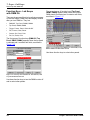
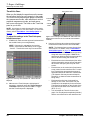
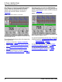
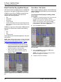
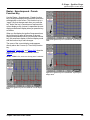
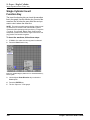
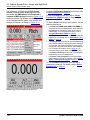
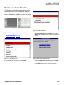
1
Scope with InfoTech
User Guide
IMPORTANT NOTICES
SAFETY DEFINITIONS
Follow all DANGER, WARNING, IMPORTANT, and Note messages in this manual.
These safety messages are defined and formatted as follows:
DANGER or WARNING: Means you risk bodily harm and /or possible loss of life.
IMPORTANT: Means the information demands special
attention or that you risk damage to the vehicle or the tool.
NOTE: Provide clarity and helpful tips.
The safety messages cover situations SPX is aware of. SPX cannot know, evaluate or advise you as to
all of the possible hazards. You must be certain that any conditions or service procedures encountered
do not jeopardize your personal safety.
COPYRIGHTS
No part of this manual may be reproduced, stored in a retrieval system or transmitted, in any form or
by any means, electronic, mechanical, photocopying, recording, or otherwise, without the prior written
permission of SPX.
Microsoft and Microsoft Windows are trademarks or registered trademarks of Microsoft Corporation in
the United States and/or other countries. Windows screen-captures may be used for instructional purposes.
This document may also include other tradenames and trademarks of SPX Corporation and other companies.
DISCLAIMER
All information, illustrations, and specifications contained in this User Guide are based on the latest
information available at the time of publication. The right is reserved to make changes at any time without
obligation to notify any person or organization of such revisions or changes. Further, SPX shall not be liable
for errors contained herein or for incidental or consequential damages (including lost profits) in connection
with the furnishing, performance or use of this material.
All software screens shown in this manual are examples. Actual test screens vary for each vehicle
being tested.
© 2005 SPX. All rights reserved.
Scope / InfoTech User Guide
Contents
IMPORTANT NOTICES . . . . . . . . . . . . . . . . . . . . . . . . . . . . . . . . . . . . . . . . . . . . . . inside front cover
Safety Precautions . . . . . . . . . . . . . . . . . . . . . . . . . . . . . . . . . . . . . . . . . . . . . . . . . . . . . . . . . . . . . . iv
General Information . . . . . . . . . . . . . . . . . . . . . . . . . . . . . . . . . . . . . . . . . . . . . . . . 1
Introduction . . . . . . . . . . . . . . . . . . . . . . . . . . . . . . . . . . . . . . . . . . . . . . . . . . . . . . . . . . . . . . . . . . . . . 1
Equipment Descriptions . . . . . . . . . . . . . . . . . . . . . . . . . . . . . . . . . . . . . . . . . . . . . . . . . . . . . . . . . . . 2
Diagnostic Tools . . . . . . . . . . . . . . . . . . . . . . . . . . . . . . . . . . . . . . . . . . . . . . . . . . . . . . . . . . . . . . . . . . . . . . .
Scope Module . . . . . . . . . . . . . . . . . . . . . . . . . . . . . . . . . . . . . . . . . . . . . . . . . . . . . . . . . . . . . . . . . . . . . . . . .
Probes (Leads) . . . . . . . . . . . . . . . . . . . . . . . . . . . . . . . . . . . . . . . . . . . . . . . . . . . . . . . . . . . . . . . . . . . . . . . .
Adapters. . . . . . . . . . . . . . . . . . . . . . . . . . . . . . . . . . . . . . . . . . . . . . . . . . . . . . . . . . . . . . . . . . . . . . . . . . . . . .
2
3
3
4
Software Description. . . . . . . . . . . . . . . . . . . . . . . . . . . . . . . . . . . . . . . . . . . . . . . . . . . . . . . . . . . . . . 4
Software Installation. . . . . . . . . . . . . . . . . . . . . . . . . . . . . . . . . . . . . . . . . . . . . . . . . . . . . . . . . . . . . . . . . . . . . 4
Software Startup . . . . . . . . . . . . . . . . . . . . . . . . . . . . . . . . . . . . . . . . . . . . . . . . . . . . . . . . . . . . . . . . . . . . . . . 5
Software Functions . . . . . . . . . . . . . . . . . . . . . . . . . . . . . . . . . . . . . . . . . . . . . . . . . . . . . . . . . . . . . . . . . . . . . 7
Setup. . . . . . . . . . . . . . . . . . . . . . . . . . . . . . . . . . . . . . . . . . . . . . . . . . . . . . . . . . . . . 9
Vehicle Entry . . . . . . . . . . . . . . . . . . . . . . . . . . . . . . . . . . . . . . . . . . . . . . . . . . . . . 11
Component Tests - InfoTech . . . . . . . . . . . . . . . . . . . . . . . . . . . . . . . . . . . . . . . . 13
Overview. . . . . . . . . . . . . . . . . . . . . . . . . . . . . . . . . . . . . . . . . . . . . . . . . . . . . . . . . . . . . . . . . . . . . . . 13
Basic Component Tests . . . . . . . . . . . . . . . . . . . . . . . . . . . . . . . . . . . . . . . . . . . . . . . . . . . . . . . . . . 13
Component Tests Function Keys. . . . . . . . . . . . . . . . . . . . . . . . . . . . . . . . . . . . . . . . . . . . . . . . . . . 15
Print Function Key . . . . . . . . . . . . . . . . . . . . . . . . . . . . . . . . . . . . . . . . . . . . . . . . . . . . . . . . . . . . . . . . . . . . . 15
Training On Function Key . . . . . . . . . . . . . . . . . . . . . . . . . . . . . . . . . . . . . . . . . . . . . . . . . . . . . . . . . . . . . . . 15
Repair Info Function Key . . . . . . . . . . . . . . . . . . . . . . . . . . . . . . . . . . . . . . . . . . . . . . . . . . . . . . . . . . . . . . . . 16
Special Component Tests . . . . . . . . . . . . . . . . . . . . . . . . . . . . . . . . . . . . . . . . . . . . . . . . . . . . . . . . . 20
Oil Light Reset Test Procedure . . . . . . . . . . . . . . . . . . . . . . . . . . . . . . . . . . . . . . . . . . . . . . . . . . . . . . . . . . .
Torque Specifications . . . . . . . . . . . . . . . . . . . . . . . . . . . . . . . . . . . . . . . . . . . . . . . . . . . . . . . . . . . . . . . . . .
Transmission Pan Identification . . . . . . . . . . . . . . . . . . . . . . . . . . . . . . . . . . . . . . . . . . . . . . . . . . . . . . . . . . .
Tune Up Specifications . . . . . . . . . . . . . . . . . . . . . . . . . . . . . . . . . . . . . . . . . . . . . . . . . . . . . . . . . . . . . . . . .
Control Module Location . . . . . . . . . . . . . . . . . . . . . . . . . . . . . . . . . . . . . . . . . . . . . . . . . . . . . . . . . . . . . . . .
20
20
20
20
20
Component Tests - Scope with InfoTech . . . . . . . . . . . . . . . . . . . . . . . . . . . . . . 23
Overview. . . . . . . . . . . . . . . . . . . . . . . . . . . . . . . . . . . . . . . . . . . . . . . . . . . . . . . . . . . . . . . . . . . . . . . 23
Basic Component Tests . . . . . . . . . . . . . . . . . . . . . . . . . . . . . . . . . . . . . . . . . . . . . . . . . . . . . . . . . . 23
Component Tests Function Keys. . . . . . . . . . . . . . . . . . . . . . . . . . . . . . . . . . . . . . . . . . . . . . . . . . . 26
Special Component Tests . . . . . . . . . . . . . . . . . . . . . . . . . . . . . . . . . . . . . . . . . . . . . . . . . . . . . . . . . 32
Oil Light Reset Test Procedure . . . . . . . . . . . . . . . . . . . . . . . . . . . . . . . . . . . . . . . . . . . . . . . . . . . . . . . . . . .
Torque Specifications . . . . . . . . . . . . . . . . . . . . . . . . . . . . . . . . . . . . . . . . . . . . . . . . . . . . . . . . . . . . . . . . . .
Transmission Pan Identification . . . . . . . . . . . . . . . . . . . . . . . . . . . . . . . . . . . . . . . . . . . . . . . . . . . . . . . . . . .
Tune Up Specifications . . . . . . . . . . . . . . . . . . . . . . . . . . . . . . . . . . . . . . . . . . . . . . . . . . . . . . . . . . . . . . . . .
Control Module Locations . . . . . . . . . . . . . . . . . . . . . . . . . . . . . . . . . . . . . . . . . . . . . . . . . . . . . . . . . . . . . . .
O2 Bar Test . . . . . . . . . . . . . . . . . . . . . . . . . . . . . . . . . . . . . . . . . . . . . . . . . . . . . . . . . . . . . . . . . . . . . . . . . .
Scope / InfoTech User Guide
32
32
32
32
32
32
i
Contents
Digital Multi-Meter (DMM). . . . . . . . . . . . . . . . . . . . . . . . . . . . . . . . . . . . . . . . . 35
Overview. . . . . . . . . . . . . . . . . . . . . . . . . . . . . . . . . . . . . . . . . . . . . . . . . . . . . . . . . . . . . . . . . . . . . . . 35
DMM Setup and Display . . . . . . . . . . . . . . . . . . . . . . . . . . . . . . . . . . . . . . . . . . . . . . . . . . . . . . . . . . 36
DMM Function Keys . . . . . . . . . . . . . . . . . . . . . . . . . . . . . . . . . . . . . . . . . . . . . . . . . . . . . . . . . . . . . 38
Overview . . . . . . . . . . . . . . . . . . . . . . . . . . . . . . . . . . . . . . . . . . . . . . . . . . . . . . . . . . . . . . . . . . . . . . . . . . . .
DMM1, DMM2, DMM3, and DMM4 Function Keys . . . . . . . . . . . . . . . . . . . . . . . . . . . . . . . . . . . . . . . . . . . .
Full Function Key . . . . . . . . . . . . . . . . . . . . . . . . . . . . . . . . . . . . . . . . . . . . . . . . . . . . . . . . . . . . . . . . . . . . . .
Freeze Function Key (DMM) . . . . . . . . . . . . . . . . . . . . . . . . . . . . . . . . . . . . . . . . . . . . . . . . . . . . . . . . . . . . .
Panel Function Key (DMM) . . . . . . . . . . . . . . . . . . . . . . . . . . . . . . . . . . . . . . . . . . . . . . . . . . . . . . . . . . . . . .
Reset Function Key . . . . . . . . . . . . . . . . . . . . . . . . . . . . . . . . . . . . . . . . . . . . . . . . . . . . . . . . . . . . . . . . . . . .
38
39
39
40
41
43
Scope - Lab Scope . . . . . . . . . . . . . . . . . . . . . . . . . . . . . . . . . . . . . . . . . . . . . . . . . 45
Overview. . . . . . . . . . . . . . . . . . . . . . . . . . . . . . . . . . . . . . . . . . . . . . . . . . . . . . . . . . . . . . . . . . . . . . . 45
Lab Scope Only (with DMM Off) . . . . . . . . . . . . . . . . . . . . . . . . . . . . . . . . . . . . . . . . . . . . . . . . . . . . 46
Screen Setup and Display . . . . . . . . . . . . . . . . . . . . . . . . . . . . . . . . . . . . . . . . . . . . . . . . . . . . . . . . . . . . . . . 46
Function Keys - Lab Scope with DMM Off . . . . . . . . . . . . . . . . . . . . . . . . . . . . . . . . . . . . . . . . . . . . . . . . . . . 50
Lab Scope with DMM On. . . . . . . . . . . . . . . . . . . . . . . . . . . . . . . . . . . . . . . . . . . . . . . . . . . . . . . . . . 51
Screen Setup and Display . . . . . . . . . . . . . . . . . . . . . . . . . . . . . . . . . . . . . . . . . . . . . . . . . . . . . . . . . . . . . . . 51
Function Keys - Lab Scope with DMM On . . . . . . . . . . . . . . . . . . . . . . . . . . . . . . . . . . . . . . . . . . . . . . . . . . . 54
Lab Scope Function Keys . . . . . . . . . . . . . . . . . . . . . . . . . . . . . . . . . . . . . . . . . . . . . . . . . . . . . . . . . 57
Overview . . . . . . . . . . . . . . . . . . . . . . . . . . . . . . . . . . . . . . . . . . . . . . . . . . . . . . . . . . . . . . . . . . . . . . . . . . . .
Trigger - Cursors - Time/Volts Function Key . . . . . . . . . . . . . . . . . . . . . . . . . . . . . . . . . . . . . . . . . . . . . . . . .
Freeze Function Key (Lab Scope) . . . . . . . . . . . . . . . . . . . . . . . . . . . . . . . . . . . . . . . . . . . . . . . . . . . . . . . . .
Panel Function Key (Lab Scope) . . . . . . . . . . . . . . . . . . . . . . . . . . . . . . . . . . . . . . . . . . . . . . . . . . . . . . . . . .
Glitch Function Key . . . . . . . . . . . . . . . . . . . . . . . . . . . . . . . . . . . . . . . . . . . . . . . . . . . . . . . . . . . . . . . . . . . .
57
57
66
69
71
Scope - Ignition Scope. . . . . . . . . . . . . . . . . . . . . . . . . . . . . . . . . . . . . . . . . . . . . . 73
Overview. . . . . . . . . . . . . . . . . . . . . . . . . . . . . . . . . . . . . . . . . . . . . . . . . . . . . . . . . . . . . . . . . . . . . . . 73
Probe Connections . . . . . . . . . . . . . . . . . . . . . . . . . . . . . . . . . . . . . . . . . . . . . . . . . . . . . . . . . . . . . . 75
Ignition Scope Only (DMM Off) . . . . . . . . . . . . . . . . . . . . . . . . . . . . . . . . . . . . . . . . . . . . . . . . . . . . . 76
Screen Setup and Display . . . . . . . . . . . . . . . . . . . . . . . . . . . . . . . . . . . . . . . . . . . . . . . . . . . . . . . . . . . . . . . 76
Function Keys - Ignition Scope with DMM Off . . . . . . . . . . . . . . . . . . . . . . . . . . . . . . . . . . . . . . . . . . . . . . . . 81
Ignition Scope with DMM On . . . . . . . . . . . . . . . . . . . . . . . . . . . . . . . . . . . . . . . . . . . . . . . . . . . . . . 82
Screen Setup and Display . . . . . . . . . . . . . . . . . . . . . . . . . . . . . . . . . . . . . . . . . . . . . . . . . . . . . . . . . . . . . . . 82
Function Keys - Ignition Scope with DMM On . . . . . . . . . . . . . . . . . . . . . . . . . . . . . . . . . . . . . . . . . . . . . . . . 85
Ignition Scope Function Keys . . . . . . . . . . . . . . . . . . . . . . . . . . . . . . . . . . . . . . . . . . . . . . . . . . . . . 88
Overview . . . . . . . . . . . . . . . . . . . . . . . . . . . . . . . . . . . . . . . . . . . . . . . . . . . . . . . . . . . . . . . . . . . . . . . . . . . .
Cursors - Time/Volts Function Key . . . . . . . . . . . . . . . . . . . . . . . . . . . . . . . . . . . . . . . . . . . . . . . . . . . . . . . .
Freeze Function Key (Ignition Scope) . . . . . . . . . . . . . . . . . . . . . . . . . . . . . . . . . . . . . . . . . . . . . . . . . . . . . .
Panel Function Key (Ignition Scope) . . . . . . . . . . . . . . . . . . . . . . . . . . . . . . . . . . . . . . . . . . . . . . . . . . . . . . .
Raster - Superimposed - Parade Function Key . . . . . . . . . . . . . . . . . . . . . . . . . . . . . . . . . . . . . . . . . . . . . . .
88
88
91
92
95
Scope - Single Cylinder. . . . . . . . . . . . . . . . . . . . . . . . . . . . . . . . . . . . . . . . . . . . . 97
Single Cylinder Setup and Display . . . . . . . . . . . . . . . . . . . . . . . . . . . . . . . . . . . . . . . . . . . . . . . . . 97
Single Cylinder Invert Function Key . . . . . . . . . . . . . . . . . . . . . . . . . . . . . . . . . . . . . . . . . . . . . . . 100
ii
Scope / InfoTech User Guide
Contents
Repair Trac . . . . . . . . . . . . . . . . . . . . . . . . . . . . . . . . . . . . . . . . . . . . . . . . . . . . . 101
Vehicle System Tests - InfoTech . . . . . . . . . . . . . . . . . . . . . . . . . . . . . . . . . . . . 103
Overview. . . . . . . . . . . . . . . . . . . . . . . . . . . . . . . . . . . . . . . . . . . . . . . . . . . . . . . . . . . . . . . . . . . . . . 103
Basic Procedure . . . . . . . . . . . . . . . . . . . . . . . . . . . . . . . . . . . . . . . . . . . . . . . . . . . . . . . . . . . . . . . 103
Vehicle System Tests Function Keys . . . . . . . . . . . . . . . . . . . . . . . . . . . . . . . . . . . . . . . . . . . . . . 105
Print Function Key . . . . . . . . . . . . . . . . . . . . . . . . . . . . . . . . . . . . . . . . . . . . . . . . . . . . . . . . . . . . . . . . . . . . 105
Training On Function Key . . . . . . . . . . . . . . . . . . . . . . . . . . . . . . . . . . . . . . . . . . . . . . . . . . . . . . . . . . . . . . 105
Repair Info Function Key . . . . . . . . . . . . . . . . . . . . . . . . . . . . . . . . . . . . . . . . . . . . . . . . . . . . . . . . . . . . . . . 106
Vehicle System Tests - Scope with InfoTech . . . . . . . . . . . . . . . . . . . . . . . . . . 109
Overview. . . . . . . . . . . . . . . . . . . . . . . . . . . . . . . . . . . . . . . . . . . . . . . . . . . . . . . . . . . . . . . . . . . . . . 109
Basic Procedure . . . . . . . . . . . . . . . . . . . . . . . . . . . . . . . . . . . . . . . . . . . . . . . . . . . . . . . . . . . . . . . 109
Vehicle System Tests Function Keys . . . . . . . . . . . . . . . . . . . . . . . . . . . . . . . . . . . . . . . . . . . . . . 111
Utility - NGIS Tool . . . . . . . . . . . . . . . . . . . . . . . . . . . . . . . . . . . . . . . . . . . . . . . 117
Overview. . . . . . . . . . . . . . . . . . . . . . . . . . . . . . . . . . . . . . . . . . . . . . . . . . . . . . . . . . . . . . . . . . . . . . 117
Glitch Sensitivity . . . . . . . . . . . . . . . . . . . . . . . . . . . . . . . . . . . . . . . . . . . . . . . . . . . . . . . . . . . . . . . 117
Calibration . . . . . . . . . . . . . . . . . . . . . . . . . . . . . . . . . . . . . . . . . . . . . . . . . . . . . . . . . . . . . . . . . . . . 118
Background Color Selection . . . . . . . . . . . . . . . . . . . . . . . . . . . . . . . . . . . . . . . . . . . . . . . . . . . . . 119
System Setup - Solarity Tool . . . . . . . . . . . . . . . . . . . . . . . . . . . . . . . . . . . . . . . 121
Overview. . . . . . . . . . . . . . . . . . . . . . . . . . . . . . . . . . . . . . . . . . . . . . . . . . . . . . . . . . . . . . . . . . . . . . 121
Basic Procedure . . . . . . . . . . . . . . . . . . . . . . . . . . . . . . . . . . . . . . . . . . . . . . . . . . . . . . . . . . . . . . . 121
Glitch Sensitivity . . . . . . . . . . . . . . . . . . . . . . . . . . . . . . . . . . . . . . . . . . . . . . . . . . . . . . . . . . . . . . . 122
Calibration . . . . . . . . . . . . . . . . . . . . . . . . . . . . . . . . . . . . . . . . . . . . . . . . . . . . . . . . . . . . . . . . . . . . 122
Contrast Adjust . . . . . . . . . . . . . . . . . . . . . . . . . . . . . . . . . . . . . . . . . . . . . . . . . . . . . . . . . . . . . . . . 123
Printer Selection . . . . . . . . . . . . . . . . . . . . . . . . . . . . . . . . . . . . . . . . . . . . . . . . . . . . . . . . . . . . . . . 123
Printer Header . . . . . . . . . . . . . . . . . . . . . . . . . . . . . . . . . . . . . . . . . . . . . . . . . . . . . . . . . . . . . . . . . 124
Unit Defaults. . . . . . . . . . . . . . . . . . . . . . . . . . . . . . . . . . . . . . . . . . . . . . . . . . . . . . . . . . . . . . . . . . . 125
Revision Levels . . . . . . . . . . . . . . . . . . . . . . . . . . . . . . . . . . . . . . . . . . . . . . . . . . . . . . . . . . . . . . . . 126
Technical Support . . . . . . . . . . . . . . . . . . . . . . . . . . . . . . . . . . . . . . . . . . . . . . . . . . . . . . . . . . . . . . 126
Hardware Tests . . . . . . . . . . . . . . . . . . . . . . . . . . . . . . . . . . . . . . . . . . . . . . . . . . . . . . . . . . . . . . . . 127
Language . . . . . . . . . . . . . . . . . . . . . . . . . . . . . . . . . . . . . . . . . . . . . . . . . . . . . . . . . . . . . . . . . . . . . 127
Disk Usage . . . . . . . . . . . . . . . . . . . . . . . . . . . . . . . . . . . . . . . . . . . . . . . . . . . . . . . . . . . . . . . . . . . . 128
File System Check . . . . . . . . . . . . . . . . . . . . . . . . . . . . . . . . . . . . . . . . . . . . . . . . . . . . . . . . . . . . . . 128
Background Color Selection . . . . . . . . . . . . . . . . . . . . . . . . . . . . . . . . . . . . . . . . . . . . . . . . . . . . . 129
Playback. . . . . . . . . . . . . . . . . . . . . . . . . . . . . . . . . . . . . . . . . . . . . . . . . . . . . . . . 131
Overview. . . . . . . . . . . . . . . . . . . . . . . . . . . . . . . . . . . . . . . . . . . . . . . . . . . . . . . . . . . . . . . . . . . . . . 131
Playback . . . . . . . . . . . . . . . . . . . . . . . . . . . . . . . . . . . . . . . . . . . . . . . . . . . . . . . . . . . . . . . . . . . . . . 131
Reference Waveforms Library . . . . . . . . . . . . . . . . . . . . . . . . . . . . . . . . . . . . . . . . . . . . . . . . . . . . 132
Copy Files to / from USB Drive (Solarity Tool only) . . . . . . . . . . . . . . . . . . . . . . . . . . . . . . . . . . . 133
Indexed Information . . . . . . . . . . . . . . . . . . . . . . . . . . . . . . . . . . . . . . . . . . . . . . 135
Order Information . . . . . . . . . . . . . . . . . . . . . . . . . . . . . . . . . . . inside back cover
Scope / InfoTech User Guide
iii
Safety Precautions
DANGER:
•
When an engine is operating, keep the service area WELL VENTILATED or attach a building
exhaust removal system to the engine exhaust system. Engines produce carbon monoxide,
an odorless, poisonous gas that causes slower reaction time and can lead to serious personal
injury or loss of life.
•
Do not exceed the limits of the tool. Doing so is dangerous and will expose you to serious
injury or possible death. Carefully read and understand all safety precautions.
•
Wear an American National Standards Institute (ANSI) approved eye shield when testing or
repairing vehicles. Objects propelled by whirling engine components or pressurized liquids
escaping may cause personal injury.
•
Set the parking brake and block the wheels before testing or repairing a vehicle. It is especially
important to block the wheels on front-wheel drive vehicles because the parking brake does not
hold the drive wheels.
•
Do not drive the vehicle and operate the tool at the same time. Any distractions may cause an
accident. Have one person operate the tool as another person drives the vehicle.
•
Maintain adequate clearance around moving components and belts during testing. Moving
components and belts can catch loose clothing, body parts, or test equipment and cause
serious damage or personal injury.
•
Refer to the service manual for the vehicle being serviced and adhere to all diagnostic
procedures and precautions. Failure to do so could result in personal injury or otherwise
unneeded repairs.
•
Do not use the tool if it is damaged.
•
Do not use the test probes if the insulation is damaged or if metal is exposed. Before connecting
test probes, make sure the vehicle’s ignition and the tool are turned off.
•
When testing for the presence of voltage or current, make sure the tool is functioning correctly.
Take a reading of a known voltage or current before accepting a zero reading.
•
When measuring current, connect in series with the load.
•
Do not exceed 800 V AC or 600 V DC voltage between any terminal and ground.
•
Use caution when measuring voltage above 25V AC or DC.
•
Do not touch the test probes, tips, or the circuit being tested.
•
Protect all circuits being tested with a 20A fuse or circuit breaker.
•
Disconnect the live test probe before disconnecting the ground test probe.
WARNING:
IMPORTANT: To avoid measuring error from outside interference, keep the tool away from
spark plug or coil wires.
iv
Scope / InfoTech User Guide
1: General Information
Introduction
The SCOPE / INFOTECH system consists of the
Scope / Multimeter software and module (also called
Scope module) and the InfoTech software.
The Scope module is an add-on module for both the
Solarity diagnostic tool and the Next Generation
Information System (NGIS) tool. The Scope module,
which has one ground port and four channel ports
(for connecting up to four probes), performs the functions of both a digital multimeter (DMM) and an oscilloscope (lab scope). The module includes special
probes (leads) and adapters.
The InfoTech software is a database of vehicle repair
information. It is compatible with both the Solarity
diagnostic tool and in the NGIS tool.
With the SCOPE / INFOTECH system installed in
either diagnostic tool, you can use the tool to do
oscilloscope tests, multimeter tests, and special
component and vehicle system tests. The special
tests let you display Scope / Multimeter live test data
and InfoTech test instructions on the screen at the
same time. They also automatically set up the tool for
some vehicle-specific tests.
If you remove the Scope module from the tool, you
can still use the InfoTech software to find special
component test instructions and other vehicle information.
For the NGIS tool, you can also use the InfoTech
software as a stand-alone database with or without
the Scope software and module installed.
This rest of this chapter provides an overview of
the SCOPE / INFOTECH system equipment and
software.
Figure 1.1: Scope / InfoTech System Components
Scope / InfoTech User Guide
1
1: General Information
Equipment Descriptions
Equipment Descriptions
Diagnostic Tools
The diagnostic tools (purchased separately) are
portable, hand-held tools that integrate the add-on
Scope module, the Scope/Multimeter software, and
the InfoTech software. You connect the scope
module to the tool and use the tool to operate the
software and Scope module.
Figure 1.2: Solarity Diagnostic Tool
This User Guide assumes you are familiar with using
the diagnostic tool. If necessary, refer to the User
Guide for the tool you are using. As a quick reference, the tool’s keys are described below.
•
ENTER — executes a selected menu option or
function.
•
EXIT — displays the previous screen or exits a
function.
•
Direction Key (Up, Down, Left, Right) — Up or Down
select a menu option or a data field. Left or Right
change the data entry within a field.
•
Function keys (four of them) — each key executes a
command that corresponds with an option listed at the
bottom of the screen.
•
HELP — displays helpful information about a
currently displayed screen.
Figure 1.3: NGIS Tool
2
Scope / InfoTech User Guide
1: General Information
Equipment Descriptions
Scope Module
Probes (Leads)
The Scope module connects to the hardware interface port (HIP) on the back of the diagnostic tool.
The Scope system includes four color-coded test
probes (yellow, red, blue, green), a ground probe,
an ignition secondary KV probe, and an ignition
synchronization probe. The probes connect to the
color-coded channel ports at the top of the Scope
module.
Color-Coded
Channel Ports
Locking
Bar
Locking
Bar
The tip of each probe removes and can be fitted
with a replacement tip or an optional tip.
NOTE: To order additional probes or accessories, contact
your OTC distributor or telephone Customer Services at
1-800-533-6127.
Ground
Port
Hardware
Interface
Port (HIP)
Figure 1.4: Scope Module - Front View
Color-Coded
Channel Ports
Locking
Bar
Locking
Bar
Ground
Port
Figure 1.6: Color Coded Test Probes - Red, Blue, Green, Yellow
Figure 1.5: Scope Module - Back View
The Scope module has the following components:
•
four color-coded channel ports on the top for connecting test probes
•
a single port on the top for connecting a ground probe
•
a HIP on the front of the module that connects to the
diagnostic tool’s HIP
•
two locking bars at the top of the module to lock it in
place on the diagnostic tool
Figure 1.7: Ground Probe (Black)
For more information, refer to 2: Setup on page 9.
Scope / InfoTech User Guide
3
1: General Information
Software Description
Software Description
Software Installation
Before using the SCOPE / INFOTECH system, the
Scope / Multimeter software and the InfoTech software must be installed in the diagnostic tool and
unlocked with a Smart Card. The software then lets
you control the Scope module with the tool.
Figure 1.8: Ignition Secondary kV Probe
The software is either preinstalled in the diagnostic
tool, provided on a compact disc or compact flash
card, or can be downloaded from the SPX web site.
For complete instructions, refer to Scan Tool Software Applications Installation and Updates (OTC
P/N 534168) or Solarity Tool Software Applications
Installation and Updates (OTC P/N 532262).
NOTE: The Scope module must be connected to the tool
during the software installation. Refer to Setup on page 9.
Figure 1.9: Ignition Synchronization Probe
Adapters
The Scope system includes a GM High Energy Ignition (HEI) adapter. For details, refer to the instructions included with the adapter.
Figure 1.11: Software CD and Smart Card
Figure 1.10: GM HEI Ignition Adapter
4
Scope / InfoTech User Guide
1: General Information
Software Description
Software Startup
The way you start the software varies for the
Solarity diagnostic tool and the NGIS scan
tool as described here and on the next page.
Solarity Diagnostic Tool
When you turn the Solarity tool on, the Application
Manager screen appears.
Figure 1.13: Solarity InfoTech Main Menu Screen, Scope Module
Connected
Figure 1.12: Application Manager Screen
You select Scope with InfoTech and press the
ENTER key to display the next screen. The menu
options that are available on the next screen and the
order of the menu options vary as follows:
•
If the Scope module is connected, the Scope with
InfoTech software starts and all of the menu options
are black to indicate they are all available for use
(Figure 1.13).
•
If the Scope module is removed, the InfoTech software starts (without Scope) and only the InfoTech
menu options are available for use. The Scope
options display at the bottom of the screen and are
grey to indicate they cannot be used. (Figure 1.14).
For more information about the options on the
main menu screens, refer to Software Functions on
page 7.
Scope / InfoTech User Guide
Figure 1.14: Solarity InfoTech Main Menu Screen, Scope Module
Removed
NOTE: The Vehicle Entry, Repair Trac, System Setup,
and Indexed Information options work the same if the
Scope module is connected or removed. The Components Tests and Vehicle System Tests options work differently if the Scope module is attached or removed, as
described in Software Functions on page 7.
5
1: General Information
Software Description
NGIS Tool
When you turn the NGIS tool on, the Application
Manager screen appears. You then choose either
the Scope with InfoTech or the InfoTech option from
the menu screens, as shown below.
NOTE: The examples below show the Graphical User
Interface. If the tool is set to Classic User Interface, the
menu options are words only instead of icons with words.
Figure 1.16: NGIS Tool Scope Multimeter Main Menu Screen
Figure 1.15: Application Manager Screen Selections
After you select a software application, the main
menu that appears (and the options on it) depends
on if the Scope module is connected (or not) and
which software you started as follows:
•
If the Scope module is connected and you select
Diagnostic Toolbox and then Scope with InfoTech
from the menu screens, the Scope with InfoTech software starts and the Scope Multimeter main menu
screen appears. All of the menu options are black to
indicate they are all available for use. (Figure 1.16).
•
If the Scope module is removed and you select Diagnostic Toolbox and then Scope with InfoTech from
the menu screens, the InfoTech software starts (without Scope) and the InfoTech main menu screen
appears. Only the InfoTech menu options are black to
indicate they are available for use. The Scope options
display at the bottom of the screen and are grey to
indicate they cannot be used. (Figure 1.17).
•
Figure 1.17: NGIS Tool InfoTech Main Menu Screen
If the Scope module is connected or removed and
you select Repair Information and then InfoTech
from the menu screens, the InfoTech software starts
and the InfoTech main menu screen appears. Only
the InfoTech menu options are available for use
(Figure 1.17).
For more information about the options on the menu
screens, refer to Software Functions on page 7.
6
Scope / InfoTech User Guide
1: General Information
Software Description
Software Functions
Digital Multi-Meter (DMM)
The options that appear on the main menu screens
access the software functions (see Figure 1.13 and
Figure 1.14 on page 5, and Figure 1.16 and Figure
1.17 on page 6). The software functions are
described below.
When you select Digital Multi-Meter, the DMM
screens appear. This option lets you use the tool
as a digital multimeter (DMM). For details, refer to
6: Digital Multi-Meter (DMM) on page 35.
Vehicle Entry
When you select Vehicle Entry, more screens
appear for you to identify the vehicle being diagnosed. You use this option to identify the vehicle
before selecting the Component Tests option.
For details, refer to 3: Vehicle Entry on page 11.
Component Tests
When you select Component Tests, the way the
function works varies if the Scope module is
connected or removed or, for the NGIS tool, if you
start only the InfoTech software as follows:
•
•
If the Scope module is connected to the tool and you
start the Scope (with InfoTech) software, the screens
display the Scope / Multimeter live test data on the top
half of the screen and the InfoTech test instructions on
the bottom half of the screen. You use this option to
perform component-specific testing; it combines the
functions of the Scope software and the InfoTech software. For details, refer to 5: Component Tests Scope with InfoTech on page 23.
If the Scope module is removed from the tool and you
start the Scope (with InfoTech) software, or, for the
NGIS tool, if you start the InfoTech software only, the
screens display the InfoTech test instructions as full
screens (without any live data readings). You use this
option to find special component test instructions and
other information. For details, refer to 4: Component
Tests - InfoTech on page 13.
Scope / InfoTech User Guide
NOTE: If the Scope module is removed from the tool or,
for the NGIS tool, if you start only the InfoTech software,
the Digital Multi-Meter option is not available for use
(it is “greyed-out”).
Scope
When you select Scope, a menu screen appears
with the options of Lab Scope, Ignition Scope, and
Single Cylinder. These options let you use the tool as
a four-channel oscilloscope. For details, refer to the
following:
•
7: Scope - Lab Scope on page 45
•
8: Scope - Ignition Scope on page 73
•
9: Scope - Single Cylinder on page 97
NOTE: If the Scope module is removed from the tool or,
for the NGIS tool, if you start only the InfoTech software,
the Scope option is not available for use (it is “greyedout”).
Repair Trac
When you select Repair Trac, a list of vehiclespecific problems (symptoms) appears for you to
look up problem-related repair information. For
details, refer to 10: Repair Trac on page 101.
7
1: General Information
Software Description
Vehicle System Tests
System Setup
When you select Vehicle System Tests, the way
the function works varies if the Scope module is
connected or removed or, for the NGIS tool, if you
start only the InfoTech software as follows:
For the Solarity diagnostic tool, when you select
System Setup, a menu screen appears for you to
select items for adjusting default settings in the tool
or for viewing information about the tool. The menu
also contains options that let you calibrate and
configure the scope module. For details, refer
to 14: System Setup - Solarity Tool on page 121.
•
•
If the Scope module is connected to the tool and you
start the Scope (with InfoTech) software, the screens
display the Scope / Multimeter live test data on the top
half of the screen and the InfoTech test instructions on
the bottom half of the screen. You use this option to
perform vehicle system testing; it combines the functions of the Scope software and the InfoTech software. For details, refer to 12: Vehicle System Tests
- Scope with InfoTech on page 109.
If the Scope module is removed from the tool and you
start the Scope (with InfoTech) software, or, for the
NGIS tool, if you start the InfoTech software only, the
screens display the InfoTech test instructions as full
screens (without any live data readings). You use this
option to find vehicle system test instructions. For
details, refer to 11: Vehicle System Tests - InfoTech
on page 103.
Playback
When you select Playback, a list of saved files
appears. This option lets you view data readings
you have previously recorded and saved with the
Component Tests, DMM, Scope, and Vehicle
System Tests functions. For details, refer to
15: Playback on page 131.
NOTE: If the Scope module is removed from the tool or,
for the NGIS tool, if you start only the InfoTech software,
the Playback option is not available for use; it is “greyedout”.
Utility
Indexed Information
For the NGIS tool, when you select Utility, a menu
screen appears with options that let you calibrate
and configure the tool. For details, refer to 13: Utility
- NGIS Tool on page 117.
When you select Indexed Information, a screen
displays the letters of the alphabet for you to look
up definitions and explanations for specific items
alphabetically. For details, refer to 16: Indexed
Information on page 135.
8
Scope / InfoTech User Guide
2: Setup
Before performing any tests with the Scope module,
you must first set up the equipment by connecting the
module to the diagnostic tool and by connecting the
probes to the module. You then clamp the probes to
the correct electrical components on the vehicle and
use the diagnostic tool for testing.
To set up the Scope module, follow these steps:
1
2
Make sure the diagnostic tool’s power is off.
If necessary, use the On/Off button to turn the
power off.
3
Position the Scope module with the front side
facing the compartment of the tool and with the
hardware interface ports aligned.
d
Place the module into the compartment and
press it into place.
e
Slide the Locking Bars in to lock the module in
place.
Connect the tool’s Power Supply into the diagnostic
tool’s Power Port and into a 110 volt wall outlet.
NOTE: Optionally, you can skip this step and use
the tool’s battery power.
Connect the Scope module to the tool as follows:
a
c
Color-Coded
Channel Ports
Position the tool to access the back side, and
open the protective HIP door.
NOTE: If necessary, remove any currently
attached module from the tool by sliding the
Locking Bars out and then pulling the module
out of the compartment.
b
On the Scope module, slide the Locking Bars
out to unlock them (you may need to hold them
out).
Locking Bars
Ground
Port
Hardware Interface
Port (HIP)
Figure 2.2: Scope Module - Back View
4
Insert the ground probe’s connector pin into the
ground port on the top of the Scope module.
5
Determine which test probe(s) are required for the test
you are doing and connect their BNC connectors to
the color-coded channel ports on the top of the Scope
module. Match the colors of the probes to the colors
of the channel ports. The channel colors are red, blue,
green, and yellow.
6
Use the diagnostic tool’s On/Off button to turn the
power on.
Figure 2.1: Scope Module Connection to Diagnostic Tool
(NGIS tool shown)
Scope / InfoTech User Guide
9
NOTES:
10
Scope / InfoTech User Guide
3: Vehicle Entry
The Vehicle Entry function lets you identify the vehicle being diagnosed. You use this option to identify
the vehicle before selecting the Component Tests
option.
To enter the vehicle information, follow these
steps:
1
Start the application to display the main menu screen.
For details, refer to Software Startup on page 5.
Figure 3.2: Vehicle Entry Screen
3
Select the vehicle manufacturer and press the
ENTER key. This displays the selected vehicle
description in the top part of the screen and changes
the bottom part of the screen to the next selection
screen in a series of selection screens, as shown
below.
NOTE: The screens shown below are examples.
Actual screens vary for each vehicle.
Figure 3.1: Main Menu Screen
2
From the main menu screen, select Vehicle Entry
and press the ENTER key. This displays the first
Vehicle Entry screen.
Figure 3.3: Series of Vehicle Entry Screens
Scope / InfoTech User Guide
11
3: Vehicle Entry
4
On each screen that appears (Figure 3.3), select the
correct option and then press the ENTER key. Do
this until the vehicle is completely identified and the
main menu screen reappears with the entire vehicle
description in the top part of the screen.
NOTE: Once you have identified a vehicle, it
remains in the software’s memory until you
identify a different vehicle.
Figure 3.4: Main Menu Screen with Vehicle Entry Completed
5
12
Select the Component Tests option as necessary.
For details, refer to 4: Component Tests - InfoTech
on page 13 and 5: Component Tests - Scope with
InfoTech on page 23.
Scope / InfoTech User Guide
4: Component Tests - InfoTech
Overview
Basic Component Tests
The InfoTech software’s Component Tests function
lets you look up special component test instructions
and other component information. The function
also lets you look up a vehicle’s Oil-Light Reset
Procedure, Torque Specifications, Trans Pan Identification, Tune-up Specifications, and Control Module
Locations.
The Component Tests function lets you look up
component test instructions for a specific vehicle.
To look up component information, follow these
steps:
1
Start the application to display the main menu screen.
For details, refer to Software Startup on page 5.
IMPORTANT: The way the Component Tests function
works varies if the Scope module is connected or
removed or, for the NGIS tool, if you start the InfoTech
software only. (For more information, refer to Software Startup on page 5.)
This chapter describes the Component Tests function if the Scope module is removed from the diagnostic tool or if you start the InfoTech software only
on the NGIS tool. The chapter includes the following
sections:
•
Basic Component Tests in the next column
•
Component Tests Function Keys on page 15
•
Special Component Tests on page 20, including
Oil Light Reset Test Procedure, Torque Specifications,Transmission Pan Identification, Tune Up
Specifications and Control Module Location.
For instructions for the Components Tests function
when the Scope module is connected to the tool,
refer to 5: Component Tests - Scope with InfoTech on page 23.
Scope / InfoTech User Guide
Figure 4.1: Main Menu Screen
2
If the correct vehicle information is not displayed in the
top part of the screen, select Vehicle Entry and
identify the vehicle. For complete instructions, refer to
3: Vehicle Entry on page 11.
13
4: Component Tests - InfoTech
Basic Component Tests
5
One or more additional screens may appear for
identifying the component. On each screen that
appears, select the correct option and then press
the ENTER key. Do this until the component is
completely identified and the Functional Tests screen
appears (Figure 4.4).
Figure 4.2: Main Menu Screen with Vehicle Entered
3
From the main menu screen, select Component
Tests. This displays a list of components on the
Component Tests screen.
NOTE: The list displays only the components
available for the vehicle being tested.
Figure 4.4: Functional Tests Screen
6
7
Figure 4.3: Component Tests Screen
4
Select a component and press the ENTER key.
NOTE: If the Repair Trac option appears on this
menu and you select it, refer to 10: Repair Trac on
page 101 for instructions. Also, refer to Special
Component Tests on page 20 for instructions for
special tests that have separate instructions.
14
Notice the following about the screen:
•
The screen displays instructions for testing the
selected component.
•
You use the Up and Down Direction keys to
scroll through the instructions.
View the instructions as necessary. While viewing the
instructions, do any of the following:
•
Use the Print function key to print the instructions. For details, refer to Print Function Key
on page 15.
•
Use the Training On function key to view Scope
Multimeter / InfoTech demonstration data. For
details, refer to Training On Function Key on
page 15.
•
Use the Repair Info function key to look up
information about the selected component.
For details, refer to Repair Info Function Key
on page 16.
NOTE: The Repair Info function key does not
always appear because some vehicle system
tests do not have additional repair information
available.
8
When finished, use the EXIT key to return to previous
screens.
Scope / InfoTech User Guide
4: Component Tests - InfoTech
Component Tests Function Keys
Component Tests Function Keys
Training On Function Key
After you have displayed the test instructions for a
component on the Functional Tests screen (Figure
4.5, below), the function keys provide additional
functions for the screen. This section describes the
following Component Tests function keys:
The Training On function key lets you view demonstration data for the Scope with InfoTech software.
•
Print - (below)
•
Training On - (next column)
•
Repair Info - (page 16) including Location, Specification, Circuit Description, Circuit Diagram, Connector,
and Reference Waveform
Print Function Key
The Print function key lets you print what is displayed
on the screen. For printing instructions, refer to the
hardware user guides for the diagnostic tool and the
printer.
Figure 4.6: Functional Tests Screen - Training On Function Key
When you press the Training On function key, the
Scope with InfoTech demonstration screen appears
(Figure 4.7). The Training function stays on until you
press the EXIT key and return to the Component
Tests screen (Figure 4.3 on page 14).
Figure 4.5: Functional Tests Screen - Print Function Key
Figure 4.7: Component Tests - Scope Multimeter Demonstration
Screen (Training On Screen)
To use the demonstration screens, refer to the
instructions in Component Tests - Scope with InfoTech on page 23.
Scope / InfoTech User Guide
15
4: Component Tests - InfoTech
Component Tests Function Keys
Repair Info Function Key
Repair Info Menu - Location Option
NOTE: The Repair Info function key does not always
appear because some vehicle system tests do not have
additional repair information available.
Use the Repair Info function key’s Location option to
view a description of the selected component’s location in the vehicle.
The Repair Info function key displays a menu of
additional functions for the selected component.
The menu options vary for each component. Possible options include the following:
•
Location
•
Specification
•
Circuit Description
•
Circuit Diagram
•
Connector
•
Reference Waveform
To view a description of the component’s location, follow these steps:
1
With the test screen displayed, press the Repair Info
function key to display the Repair Info menu.
These options are described separately in the next
few sections.
NOTE: If you press the Repair Info function key to display
the menu, but do not want to select an option, press the
EXIT key or press the Repair Info function key again to
close the menu.
Figure 4.9: Component Tests - Repair Info Function Key
2
Select Location and press the ENTER key.
This displays the Location screen.
Figure 4.8: Component Tests - Repair Info Function Key
Figure 4.10: Repair Info Function Key, Location Screen
16
3
View the description and optionally use the Print
function key to print it.
4
When finished, press the Back function key to return
to the previous screen.
Scope / InfoTech User Guide
4: Component Tests - InfoTech
Component Tests Function Keys
Repair Info Menu - Specification Option
Use the Repair Info function key’s Specification
option to view specifications for the selected
component.
To view the specifications, follow these steps:
1
With the test screen displayed, press the Repair Info
function key to display the Repair Info menu.
Repair Info Menu Circuit Description Option
Use the Repair Info function key’s Circuit Description
option to view a description of the circuit for the
selected component.
To view the circuit description, follow these
steps:
1
With the test screen displayed, press the Repair Info
function key to display the Repair Info menu.
Figure 4.11: Component Tests - Repair Info Function Key
2
Select Specification and press the ENTER key.
This displays the Specifications screen.
Figure 4.13: Component Tests - Repair Info Function Key
2
Select Circuit Desc. and press the ENTER key.
This displays the Circuit Description screen.
Figure 4.12: Repair Info Function Key, Specifications Screen
3
View the information and optionally use the Print
function key to print it.
Figure 4.14: Repair Info Function Key, Circuit Description Screen
4
When finished, press the Back function key to return
to the previous screen.
3
View the description and optionally use the Print
function key to print it.
4
When finished, press the Back function key to return
to the previous screen.
Scope / InfoTech User Guide
17
4: Component Tests - InfoTech
Component Tests Function Keys
Repair Info Menu - Circuit Diagram Option
Repair Info Menu - Connector Option
Use the Repair Info function key’s Circuit Diagram
option to view a diagram of the circuit for the selected
component.
Use the Repair Info function key’s Connector option
to view a diagram of connector(s) for the selected
component.
To view the circuit diagram, follow these steps:
To view the connector diagram, follow these
steps:
1
With the test screen displayed, press the Repair Info
function key to display the Repair Info menu.
1
With the test screen displayed, press the Repair Info
function key to display the Repair Info menu.
Figure 4.15: Component Tests - Repair Info Function Key
2
Select Ckt Diagram and press the ENTER key.
This displays the Circuit Diagram screen.
Figure 4.17: Component Tests - Repair Info Function Key
2
Select Connector and press the ENTER key.
This displays the Connector Diagram screen.
Figure 4.16: Repair Info Function Key, Circuit Diagram Screen
3
View the diagram and optionally use the Print function
key to print it.
4
When finished, press the Back function key to return
to the previous screen.
18
Figure 4.18: Repair Info Function Key, Connector Diagram
Screen
3
View the diagram and optionally use the Print function
key to print it.
4
When finished, press the Back function key to return
to the previous screen.
Scope / InfoTech User Guide
4: Component Tests - InfoTech
Component Tests Function Keys
Repair Info Menu Reference Waveform Option
NOTE: The Reference Waveform (Ref Wave) option
appears only when you have the Training function turned
on or when are using the Scope with InfoTech software
(with the Scope module connected to the tool).
Use the Repair Info function key’s Reference Waveform (Ref Wave) option to view an example of a
waveform for the selected component.
To view the reference waveform, follow these
steps:
1
With the test screen displayed, press the Repair Info
function key to display the Repair Info menu.
Figure 4.20: Repair Info Function Key, Ref. Waveform Option
3
View the waveform and optionally use the Print
function key to print it.
4
If there is a Bad function key, use the function key to
view an example of a known-bad waveform.
NOTE: When you use the Bad function key, the
name of the Bad function key changes to Good.
Use the Good function key to return to the display
of the known-good waveform.
5
Use the Back function key to return to the previous
screen.
Figure 4.19: Component Tests - Repair Info Function Key
2
Select Ref. Wave and press the ENTER key.
This displays the reference waveform in the bottom
half of the screen.
Scope / InfoTech User Guide
19
4: Component Tests - InfoTech
Special Component Tests
Special Component Tests
Oil Light Reset Test Procedure
Torque Specifications
Transmission Pan Identification
Tune Up Specifications
Control Module Location
The Component Tests function lets you look up an
oil light reset test procedure, torque specifications,
the transmission pan identification, tune up specifications, and control module locations for some
vehicles.
Figure 4.22: InfoTech Main Menu Screen with Vehicle Entered
3
To look up special component test instructions,
follow these steps:
1
2
NOTE: Test options vary for each vehicle. Only the
options available for a vehicle appear on this list.
Start the application to display the main menu screen.
For details, refer to Software Startup on page 5.
Figure 4.21: Main Menu Screen
If the correct vehicle information is not displayed in
the top part of the screen, select Vehicle Entry and
identify the vehicle. For complete instructions, refer to
3: Vehicle Entry on page 11.
From the main menu screen, select Component
Tests. This displays a list of components on the
Component Tests screen.
Figure 4.23: Component Tests Screen
4
Select one of the special tests (Oil Light Reset Test
Procedure, Torque Specifications, Trans Pan
Identification, Tune Up Specifications, or Control
Module Location) and press the ENTER key. This
displays the information screen for the selected item
as shown in Figure 4.24, Figure 4.25, Figure 4.26,
Figure 4.27, and Figure 4.28 on page 21.
NOTE: The options are at the very bottom of the
list, if available.
20
Scope / InfoTech User Guide
4: Component Tests - InfoTech
Special Component Tests
Figure 4.24: Oil Light Reset Test Procedure Screen
Figure 4.27: Tune-Up Specs Screen
Figure 4.25: Torque Specifications Screen
Figure 4.28: Control Module Location Screen
5
View the information and optionally use the Print
function key to print it.
6
When finished, press the Back function key to return
to the Component Tests screen.
Figure 4.26: Trans-Pan Identification Screen
Scope / InfoTech User Guide
21
NOTES:
22
Scope / InfoTech User Guide
5: Component Tests Scope with InfoTech
Overview
Basic Component Tests
The Scope with InfoTech software’s Component
Tests function lets you perform vehicle component
testing. The Component Tests screens display
Scope / Multimeter live test data and InfoTech test
instructions on the same screen (see Figure 5.6 on
page 25). This combines the functions of the Scope
software and the InfoTech software so you can view
test instructions while performing tests.
To use the Component Tests function, follow
these steps:
1
Start the application to display the main menu screen.
For details, refer to Software Startup on page 5.
IMPORTANT: The way the Component Tests function
works varies if the Scope module is connected or
removed or, for the NGIS tool, if you start the InfoTech
software only. (For more information, refer to Software Startup on page 5.)
This chapter describes the Component Tests function if the Scope module is connected to the diagnostic tool and, for the NGIS tool, if you start the Scope
with InfoTech software. The chapter includes the
following sections:
•
Basic Component Tests in the next column
•
Component Tests Function Keys on page 26
Figure 5.1: Main Menu Screen
•
Special Component Tests on page 32 including
Oil Light Reset Test Procedure, Torque Specifications, Transmission Pan Identification, Tune Up
Specifications, Control Module Locations, and
O2 Bar Test.
2
If the correct vehicle information is not displayed in
the top part of the screen, select Vehicle Entry and
identify the vehicle. For complete instructions, refer to
3: Vehicle Entry on page 11.
For instructions for the Component Tests function
when the Scope module is removed from the tool
and, for the NGIS tool, if you start the InfoTech software, refer to 4: Component Tests - InfoTech on
page 13.
Scope / InfoTech User Guide
23
5: Component Tests - Scope with InfoTech
Basic Component Tests
5
One or more additional screens may appear for
identifying the component. On each screen that
appears, select the correct option and then press
the ENTER key. Do this until the component is
completely identified and the test screen appears
(Figure 5.4 or Figure 5.6).
Figure 5.2: Main Menu Screen with Vehicle Entered
3
From the main menu screen, select Component
Tests. This displays a list of components on the
Component Tests screen.
NOTE: Test options vary for each vehicle. Only the
options available for a vehicle appear on this list.
Figure 5.4: Component Test Screen with Test List in Bottom Panel
NOTE: Depending on the test selected, the top half
of the test screen displays either a scope waveform
(shown above) or two digital multimeter (DMM)
readings as described in step 7 (see Figure 5.5
and Figure 5.6).
6
Figure 5.3: Component Tests Screen
4
If there are multiple tests for the component, the
bottom half of the screen displays a list of tests.
If the list appears, do one of the following:
•
Use the screen for testing. The screen operates similar to the screen with test instructions
displayed in the bottom half of the screen
(Figure 5.5), or
•
Select a Test and press the ENTER key. This
displays the test screen with the InfoTech test
instructions in the bottom half of the screen
(Figure 5.5).
Select a component and press the ENTER key.
NOTE: If the Repair Trac option appears on this
menu and you select it, refer to 10: Repair Trac on
page 101 for instructions. Also, refer to Special
Component Tests on page 32 for instructions for
the special tests that have separate instructions.
24
Scope / InfoTech User Guide
5: Component Tests - Scope with InfoTech
Basic Component Tests
Figure 5.5: Component Test Screen with Scope Waveform in Top
Panel and Test Instructions in Bottom Panel
7
The bottom half (panel) of the screen displays
the InfoTech test instructions for the test. This
display operates similar to the InfoTech test
instructions described in 4: Component Tests
- InfoTech on page 13.
•
One panel is always “selected.” When you
first display the screen, the bottom panel
(test instructions) is selected. You use the
Up and Down Direction keys to scroll through
the instructions. To select the top panel, you
press the Panel function key and select a panel
option (Edit Scope or DMM1 / DMM2).
•
If the top half of the screen displays a waveform
panel and is selected, you use the Direction
keys to adjust the waveform settings.
•
If the top half of the screen is displays two DMM
panels and a DMM panel is selected, if the
selected panel’s border a solid black line, the
Direction keys move within the panel for changing the edit fields. If the selected panel’s border
is moving dashes, you use the Left and Right
Direction keys to select the other DMM panel.
•
If a top panel is selected, you must press the
EXIT key to select the bottom (test instructions)
panel again.
•
The function keys at the bottom of the screen
change based on which panel is currently
selected. For details, refer to Component
Tests Function Keys on page 26
8
Use the instructions and the test screen to perform
the component test, using the function keys to move
between the panels, adjust the waveform and DMM
readings, print and save data, freeze and reset the
readings, turn on a training function, and view
additional repair information as necessary. For details
about the function keys, refer to Component Tests
Function Keys on page 26.
9
When finished, use the EXIT key to return to previous
screens.
Figure 5.6: Component Test Screen with Two DMM Readings in
Top Panel and Test Instructions in Bottom Panel
NOTE: If there are no test instructions available, a
message appears in the bottom half of the screen.
•
Notice the following about the test screen:
•
The top half of the screen displays either a
Scope waveform panel (Figure 5.5) or two
DMM panels (Figure 5.6).
»
A waveform display operates the same as
the Lab Scope waveform display (with
DMM off). For a complete description of
the display, refer to page 48 in 7: Scope Lab Scope on page 45.
»
A DMM display operates the same as a
full screen DMM display. For a complete
description of the DMM panels, refer to
6: Digital Multi-Meter (DMM) on page 35.
Scope / InfoTech User Guide
25
5: Component Tests - Scope with InfoTech
Component Tests Function Keys
Component Tests Function Keys
The function keys at the bottom of the Component
Tests screen provide additional functions for using
the screen. The function keys change based on
which panel is currently selected. There are six
groups of function keys that appear on the screen.
The are:
•
Print, Freeze, Panel, Repair Info (see page 26)
•
Trigger/Cursors/Time Volts, Freeze, Panel, Glitch
On/Off (see page 28)
•
Full Screen/Restore, Freeze, Panel, Reset
(see page 29)
•
Panel (see page 30)
•
Cursors, Go, Panel, Print (see page 30)
•
Full / Restore, Go, Panel, Print (see page 31)
The first group of function keys [Print, Freeze,
Panel, Repair Info] appears when the bottom
panel is selected and it contains the test list or
test instructions, as shown in Figure 5.7, Figure
5.8, and Figure 5.9.
These groups of function keys are described in the
next few sections.
Figure 5.7: Component Test Screen - Function Keys with Scope
Waveform in Top Panel and Bottom Panel Selected
Figure 5.8: Component Test Screen - Function Keys with Scope
Waveform in Top Panel and Bottom Panel Selected
26
Scope / InfoTech User Guide
5: Component Tests - Scope with InfoTech
Component Tests Function Keys
To use the Panel function key menu options, use the
following instructions:
•
Figure 5.9: Component Test Screen - Function Keys with DMM
Readings in Top Panel and Bottom Panel Selected
To use the Print function key, press the key to print
the test instructions. Refer to the hardware user
guides for the diagnostic tool and the printer.
•
When the top panel displays a waveform and the
bottom panel is selected, the Panel menu contains
the options Edit Scope and DMM1/DMM2. Use them
as follows:
»
Use Panel, Edit Scope to select the top,
waveform panel. With the panel selected, the
screen operates the same as the normal Lab
Scope waveform display (with DMM off).
For a complete description, refer to page 48.
(To select the bottom panel again, press the
EXIT key.)
»
Use Panel, DMM1/DMM2 to replace the top
panel waveform with two DMM panels.
When the top panel displays DMM readings and the
bottom panel is selected, the Panel menu contains
the options DMM1, DMM2, Scope, and Training
On/Off.
»
Use DMM1, DMM2 or Edit DMM1, Edit DMM2
to select and edit the top DMM panels. When
selected, the DMM panels operate the same
as the normal DMM display. For a complete
description, refer to 6: Digital Multi-Meter
(DMM) on page 35.
To use the Freeze function key, refer to the following
sections:
»
Use Panel, Scope to replace the top two DMM
panels with a Scope waveform.
•
When the top panel displays a waveform, refer to the
instructions in Freeze Function Key (Lab Scope) on
page 66. Begin with step 2.
»
•
When the top panel displays DMM readings, refer to
the instructions in Freeze Function Key (DMM) on
page 40. Begin with step 2.
Use Panel, Training On/Off to turn demonstration data readings on and off. For details,
refer to Panel Menu - Training On/Off Option
on page 71.
NOTE: The print function key does not appear
when the bottom panel displays a test list instead of
instructions (see Figure 5.7).
Scope / InfoTech User Guide
To use the Repair Info function key, refer to Repair
Info Function Key on page 106.
27
5: Component Tests - Scope with InfoTech
Component Tests Function Keys
The second group of function keys [Trigger/
Cursors/Time Volts, Freeze, Panel, Glitch On/Off]
appears when the top panel is selected and it
contains the waveform display, as shown in Figure
5.10, or when the top panel is selected and the Glitch
panel is displayed in the bottom half of the screen, as
shown in Figure 5.11. They also appear when you
display a full screen waveform by using the Panel
function key Full Screen option, as shown in Figure
5.12.
Figure 5.12: Component Test Screen - Function Keys with
Waveform Selected and Displayed as Full Screen
To use the Trigger / Cursors / Time Volts function
key, refer to Trigger - Cursors - Time/Volts Function Key on page 57.
To use the Freeze function key, refer to Freeze
Function Key (Lab Scope) on page 66. Begin with
step 2.
Figure 5.10: Component Test Screen - Function Keys with
Waveform in Top Panel Selected
Figure 5.11: Component Test Screen - Function Keys with Glitch
On
28
To use the Panel function key menu options, use the
following instructions:
•
Use Panel, DMM1/DMM2 to replace the top panel
waveform with two DMM panels.
•
Use Panel, Auto Setup to have the Scope software
automatically set up the waveform in the graph.
•
Use Panel, Grid On / Off to turn the waveform’s grid
lines on or off. For details, refer to Panel Menu - Grid
Off/On Option on page 70.
•
Use Panel, Training On/Off to turn demonstration
data readings on and off. For details, refer to Panel
Menu - Training On/Off Option on page 71.
•
Use Panel, Full Screen to change the split screen
display to a full screen display as shown in Figure
5.12. With the full screen displayed, the menu option
becomes Split Screen. Select the Split Screen option
to return the display to a split screen (Figure 5.10).
To use the Glitch On / Off function key, refer to
Glitch Function Key on page 71.
Scope / InfoTech User Guide
5: Component Tests - Scope with InfoTech
Component Tests Function Keys
The third group of function keys [Full Screen/
Restore, Freeze, Panel, Reset] appears when one
of the top DMM panels is selected and it contains
a DMM reading, as shown in Figure 5.13. When you
use the Full Screen function key, the full screen
displays and the name of the function key changes
to Restore, as shown in Figure 5.14.
Figure 5.13: Component Test Screen - Function Keys with DMM
Reading Selected
To use the Full Screen / Restore function key, refer
to Full Function Key on page 39.
To use the Freeze function key, refer to Freeze
Function Key (DMM) on page 40. Begin with
step 2.
To use the Panel function key menu options, use the
following instructions:
•
Use Panel, Edit DMM (Edit DMM1, Edit DMM2) to
select and edit the top DMM panels. When selected,
the DMM panels operate the same as the normal
DMM display. For a complete description, refer to
6: Digital Multi-Meter (DMM) on page 35.
•
Use Panel, Zero to restart the readings for a selected
DMM panel. For details, refer to Panel Menu - Zero
Option on page 42.
•
Use Panel, Scope to replace the top two DMM panels
with a Scope waveform. With the waveform displayed
and selected, the screen operates the same as the
normal Lab Scope waveform display (with DMM off).
For a complete description, refer to page 48. (To
select the bottom panel again, press the EXIT key.)
•
Use Panel, Auto Setup to have the Scope software
automatically set up the DMM panels.
•
Use Panel, Training On/Off to turn demonstration
data readings on and off. For details, refer to Panel
Menu - Training On/Off Option on page 71.
To use the Reset function key, press the key to
restart all the readings. For details, refer to Reset
Function Key on page 43.
Figure 5.14: Component Test Screen - Function Keys with DMM
Reading Selected and Displayed as Full Screen
Scope / InfoTech User Guide
29
5: Component Tests - Scope with InfoTech
Component Tests Function Keys
The fourth group of function keys [blank, blank,
Panel, blank] appears when one of the top DMM
panels is selected and it contains edit fields, as
shown in Figure 5.15.
The fifth group of function keys [Cursors, Go, Panel,
Print] shown in Figure 5.16 appears when the top
panel displays a waveform and you use the
Freeze function key.
Figure 5.15: Component Test Screen - Function Keys with DDM
Edit Fields Panel Selected
Figure 5.16: Component Test Screen - Function Keys with
Waveform in Top Panel Selected and Frozen
Use these function keys to select the panels for
changing the setup. For instructions, refer to
DMM Setup and Display on page 36.
To use these function keys, refer to Freeze Function
Key (Lab Scope) on page 66.
30
NOTE: When you use the Freeze function key, the
options on the Panel menu change to Playback and Save.
These options are also described in Freeze Function Key
(Lab Scope) on page 66.
Scope / InfoTech User Guide
5: Component Tests - Scope with InfoTech
Component Tests Function Keys
The sixth group of function keys [Full/Restore, Go,
Panel, Print] as shown in Figure 5.17 appears when
the top panels display DMM readings and you
use the Freeze function key. When you use the Full
Screen function key, the full screen displays and the
name of the function key changes to Restore, as
shown in Figure 5.18
Figure 5.18: Component Test - Function Keys with DMM Reading
in Top Panel Selected and Frozen and Displayed as Full Screen
To use the Full function key, refer to Full Function
Key on page 39 in 6: Digital Multi-Meter (DMM).
To use the Go, Panel, and Print function keys, refer
to Freeze Function Key (DMM) on page 40.
Figure 5.17: Component Test - Function Keys with DMM Reading
in Top Panel Selected and Frozen
Scope / InfoTech User Guide
NOTE: When you use the Freeze function key, the
options on the Panel menu change to Playback and Save.
These options are also described in Freeze Function Key
(DMM) on page 40.
31
5: Component Tests - Scope with InfoTech
Special Component Tests
Special Component Tests
2
The Component Tests function lets you look up an oil
light reset test procedure, torque specifications, the
transmission pan identification, tune up specifications, and control module locations for some vehicles. It also lets you perform a special O2 Bar Test.
If the correct vehicle information is not displayed in the
top part of the screen, select Vehicle Entry and
identify the vehicle. For complete instructions, refer to
3: Vehicle Entry on page 11.
Oil Light Reset Test Procedure
Torque Specifications
Transmission Pan Identification
Tune Up Specifications
Control Module Locations
These tests work the same in both the Scope with
InfoTech software and the InfoTech software. For
instructions, refer to Special Component Tests on
page 20.
Figure 5.20: InfoTech Main Menu Screen with Vehicle Entered
3
O2 Bar Test
From the main menu screen, select Component
Tests. This displays a list of components on the
Component Tests screen.
NOTE: Test options vary for each vehicle. Only the
options available for a vehicle appear on this list.
The Scope with InfoTech software has a special O2
Bar Component Test that is different from the other
Component Tests.
To use the O2 Bar Test function, follow these
steps:
1
Start the application to display the main menu screen.
For details, refer to Software Startup on page 5.
Figure 5.21: Component Tests Screen
4
Select O2 BAR Test and press the ENTER key.
This displays the O2 BAR test on the Component
Test screen (Figure 5.22).
NOTE: The O2 BAR Test option is near the bottom
of the list, if available.
Figure 5.19: Main Menu Screen
32
Scope / InfoTech User Guide
5: Component Tests - Scope with InfoTech
Special Component Tests
•
Makes the top waveform panel the “selected”
panel. (If the panel has a moving-dashes
border, press the ENTER key to edit the waveform. To select the bottom panel again, press
the EXIT key and then use the Down Direction
key.)
NOTE: For information about using cursors,
refer to Trigger - Cursors - Time/Volts
Function Key on page 57.
Figure 5.22: Component Test Screen - O2 BAR Test
5
Notice the following about the test screen:
•
The top half of the screen displays the Scope
waveform for the test. This display operates the
same as the Lab Scope waveform display
(with DMM off). For a complete description of
the display, refer to page 48 in 7: Scope - Lab
Scope.
•
The bottom half (panel) of the screen displays
the InfoTech test instructions for the test. This
display operates similar to the InfoTech test
instructions described in 4: Component Tests
- InfoTech on page 13.
•
One panel is always “selected.” When you first
display the screen, the top waveform panel is
selected.
•
The function keys at the bottom of the screen
change based on which panel is currently
selected.
6
Press the EXIT key and then use the Down Direction
key to select the bottom panel.
7
Use the Up and Down Direction keys to scroll
through the test instructions.
8
Figure 5.23: Component Test Screen - O2 BAR Test with Cursors
9
Use the function keys to move between the panels,
adjust the waveform, display DMM readings, print and
save data, freeze and reset the readings, and turn on
a training function. For instructions for the function
keys, refer to Component Tests Function Keys on
page 26. Be aware of the following differences in the
O2 Bar Test function keys:
•
If the bottom panel contains the test instructions and the panel is selected, you must
use the Calc Results function key to select
the top waveform panel. This freezes the readings. Press the Go function key to restart the
readings.
•
The Panel function key DMM option places two
DMM panels in the bottom half of the screen.
With the DMM panels displayed, the Panel
function key, Test Text option places the test
instructions back into the bottom half of the
screen.
•
If the DMM panels are displayed in the bottom
half of the screen and the top panel is selected,
you must press the EXIT key and then use the
Direction keys to move between the panels.
As you perform the test, when you get to the test
instruction step that says “When the voltage rises
above .800 volts, freeze / record the signal,” press the
Calc Results function key. This does the following:
•
Stops the readings (see Figure 5.23),
•
Places cursors at the last place the voltage was
below the lower limit (0.175V) and the first
place after that where the voltage was above
the upper limit (0.800V),
•
Calculates the time difference as the difference
between the vertical cursors, and
Scope / InfoTech User Guide
10 When finished, use the EXIT key to return to previous
screens.
33
NOTES:
34
Scope / InfoTech User Guide
6: Digital Multi-Meter (DMM)
Overview
Digital
Bar
The Digital Multi-Meter function lets you view up to
four different meters on one screen. Based on your
testing requirements, you can set up the meters to
display various combinations of channel readings.
When you select Digital Multi-Meter from the
Scope Multimeter main menu screen, the Digital
Multi-Meter (DMM) Panel Setup screen appears.
Dial
Strip
Figure 6.2: Digital Multi-meter Screen - After Setup
Figure 6.1: Digital Multi-meter Panel Setup Screen
This screen contains four panels for setting up four
different digital multi-meter displays (for up to four
channels). After setting up the panels, the multimeter readings display in each panel, as shown in
Figure 6.2.
Scope / InfoTech User Guide
You can view each meter reading as a digital readout, bar graph, dial, or strip (line) graph. You can also
view each meter individually on the full screen, use a
training function, use an automatic setup function, or
“freeze” a screen of data for viewing, printing, or
saving.
This chapter describes how to use the Digital MultiMeter functions.
35
6: Digital Multi-Meter (DMM)
DMM Setup and Display
DMM Setup and Display
3
Notice the following about the Setup Screen:
•
The screen has four panels for setting up
four different meter readings. You set up the
panels, one at a time, based on the probes
connected to the Scope module and your testing requirements. After you set up a panel and
press the ENTER key, the meter reading
appears directly in the panel (in place of the
setup boxes).
•
One panel is always “selected.” The selected
panel either has a solid border around it and
contains edit “fields” (Figure 6.4), or it has a
“moving” dashes border and contains a meter
reading (Figure 6.6 on page 37).
•
When the selected panel’s border is solid,
the Direction keys move within the panel for
changing the edit fields. When the selected
panel’s border is moving dashes, the Direction
keys move between panels for selecting other
panels.
•
The Scope software has a training demo function. To use this right away, press the ENTER
key. Then press the Panel function key, select
Training On from the menu, and press the
ENTER key. For details, refer to Panel Menu Training On/Off Option on page 43.
•
The DMM screen has an automatic setup
feature that determines range values for you
based on the electrical signals through the
channel(s). Details are included in the following
steps.
To set up and display the digital multi-meter
readings, follow these steps:
1
Display the main menu screen. For details, refer to
Software Startup on page 5.
Figure 6.3: Main Menu Screen
2
From the main menu screen, select Digital MultiMeter. This displays the digital multi-meter setup
screen.
Figure 6.4: DMM Setup Screen
36
Scope / InfoTech User Guide
6: Digital Multi-Meter (DMM)
DMM Setup and Display
4
Do the following to adjust the panel’s settings:
5
NOTE: The selected panel may still contain the
settings from the last time you used it. If the panel
is already set correctly, go to step 5.
When finished setting up a panel, press the ENTER
key to display the meter reading. The solid black
border around the panel changes to moving dashes,
indicating you can now use the Direction keys to
select another panel. See Figure 6.6.
NOTE: After changing the values and before
pressing the ENTER key, you can optionally press
the EXIT key and not display the meter reading right
away, but come back and change or view it later
(after setting up the other panels).
Figure 6.5: DMM Panel 1
a
Use the Left and Right Direction keys to
select the channel color of the probe you want
to read from.
NOTE: To turn a panel off, set the Channel to
Off and then press either the EXIT key or a
DMM function key.
b
Use the Down Direction key to select the next
field.
c
Use the Left and Right Direction keys to set
the value for the selected field.
d
Repeat b and c until all the values are set
correctly, then go to the next step. The table
below lists possible field values.
Field
Possible Values
Channel
Red, Blue, Green, Yellow, Off
Measure
Varies based on the selected Channel color:
Amps, DC Volts, AC Volts, RMS, Frequency,
Duty Cycle, O2 Cross Counts, Ohms
Range
Varies based on the selected Measure
NOTE: Select “Auto Range” to have the
software automatically adjust the range as
necessary during testing.
Display
Figure 6.6: DMM Screen - Panel 1 Displayed
NOTE: Each displayed panel shows the measurement and range at the top, the reading in the
center, and the reading’s minimum, average, and
maximum at the bottom. If a panel is selected, you
can repeatedly press the ENTER key to change the
panel’s display type from Digital to Bar to Dial to
Strip (see Figure 6.7 on page 38).
6
To set up another panel, use the Direction keys to
select the panel to set up. This places the moving
dashes around the newly selected panel.
7
With the panel selected, press the ENTER key to
begin editing the panel. This changes the border
to a solid black line.
8
Return to step 4 and repeat steps 4 through 7 until all
the panels are set up as you want them. Figure 6.7
shows all four panels set up.
Identifies how the reading appears: Digital,
Bar, Dial, or Strip
NOTE: You can optionally use the Auto Setup function
to have the software automatically set up the Range
values for multiple panels. To do this, “turn on” each panel
you want to use by setting the Channel and Measure
values and then displaying the panel. With all the required
panel meter readings displayed, press the Panel function
key, select Auto Setup from the menu, and press the
ENTER key. Then go to step 9. For more information, refer
to Panel Menu - Auto Setup Option on page 42.
Scope / InfoTech User Guide
37
6: Digital Multi-Meter (DMM)
DMM Function Keys
DMM Function Keys
Overview
The function keys at the bottom of the multi-meter
screen change when the selected panel’s border
and contents change, and when you use the Freeze
function. The three main groups of Function keys
that appear on the DMM screens are:
Figure 6.7: DMM Screen -All Panels Displayed
9
While viewing the readings, do any of the following:
•
•
With a display panel selected (with a movingdashes border), repeatedly press the ENTER
key to change the display type (Digital, Bar,
Dial, Strip) for that panel.
Use the Full function key to view a selected
panel as a full-screen display. Refer to Full
Function Key on page 39.
•
Use the Freeze function key to stop the readings and “freeze” them on the screen. Refer to
Freeze Function Key (DMM) on page 40.
•
Use the Panel function key, Edit option to
change the settings for a panel. Refer to Panel
Menu - Edit Option on page 41.
•
Use the Panel function key, Zero option to reset
the readings for a selected panel. Refer to
Panel Menu - Zero Option on page 42.
•
Use the Panel function key, Auto Setup option
to have the Scope software automatically
determine the Range settings for the displayed
panels. Refer to Panel Menu - Auto Setup
Option on page 42.
•
Use the Panel function key, Training On/Off
option to view demo readings in the panels.
Refer to Panel Menu - Training On/Off Option
on page 43.
•
Use the Reset function key to reset the readings for all panels. Refer to Reset Function
Key on page 43.
•
DMM1, DMM2, DMM3, DMM4
•
Full, Freeze, Panel, Reset
•
Full, Go, Panel, Print
The first two groups of function keys appear based
on the selected panel’s border and contents as
shown in the following table.
Border/Contents Function Keys
Solid border;
Contains edit
fields
DMM1, DMM2, DMM3, DMM4
(see Figure 6.8)
For details, refer to DMM1, DMM2, DMM3,
and DMM4 Function Keys on page 39.
Moving border;
Contains the
meter reading
Full, Freeze, Panel, Reset
(see Figure 6.9)
For details, refer to the following:
•
•
•
•
Full Function Key on page 39
Freeze Function Key (DMM) on
page 40
Panel Function Key (DMM) on page
41
Reset Function Key on page 43
The third group of Function keys [Full, Go, Panel,
Print] appears when you use the Freeze function
key (see Figure 6.10). For details, refer to Freeze
Function Key (DMM) on page 40.
10 When you are finished using the screen, use the EXIT
key to return to the main menu screen.
38
Scope / InfoTech User Guide
6: Digital Multi-Meter (DMM)
DMM Function Keys
DMM1, DMM2, DMM3, and DMM4
Function Keys
Use the DMM 1, DMM2, DMM3, and DMM4 function
keys to select other panels for setup and viewing.
Full Function Key
The Full function key lets you view a selected panel’s
meter reading on the entire (full) screen.
To display the full screen, follow these steps:
1
Select a panel for full display. The panel must
currently display a meter reading.
Figure 6.8: DMM Function Keys - Solid Border with Edit Fields
Figure 6.11: DMM Screen - Full Function Key
Figure 6.9: DMM Function Keys - Moving Border with Meter
Reading
2
Press the Full function key. This changes the screen
to the full display for the selected panel.
Figure 6.12: DMM Screen - Full Display
Figure 6.10: DMM Function Keys - after pressing Freeze function
key
Scope / InfoTech User Guide
3
When finished, press the Restore function key to
return to the four-panel DMM display screen.
39
6: Digital Multi-Meter (DMM)
DMM Function Keys
Freeze Function Key (DMM)
3
The DMM’s Freeze function key lets you stop and
“freeze” the meter reading(s) at one specific point in
time. When the reading(s) are “frozen,” you can print
or save the reading(s), or review already saved
readings.
To “freeze” the readings, follow these steps:
1
Select any panel that currently displays a meter
reading.
Use the Function keys on the “frozen” screen to do
any of the following:
•
Full - use this function key to view a selected
panel on the entire (full) screen. When finished
viewing the full screen, press the Restore function key to return to the four-panel DMM display
screen.
•
Go - use this function key to restart the live
readings.
•
Panel: Playback - use this function key to view
saved files. When you use this key, a Load
screen appears for selecting a file to view. Use
the Up and Down Direction keys to select a
file and then press the ENTER key.
NOTE: You can also use the Playback option
on the main menu to “playback” files. For
details, refer to 15: Playback on page 131.
•
NOTE: The Save screen lists saved files and
“Open” positions. When you save a new file you
can either select an “Open” position or a file you
want to over-write. The function keys at the
bottom of the screen let you lock or unlock files.
Locked files have a padlock icon next to the file
name; they cannot be overwritten.
Figure 6.13: DMM Screen - Freeze Function Key
2
Panel: Save - use this function key to save a
“snapshot” of what is currently displayed on the
screen. When you use this key, a Save screen
appears for saving a file. Use the Up and
Down Direction keys to select an “Open”
position and then press the ENTER key.
Press the Freeze function key. This stops all readings
and “freezes” the display for all the panels. The word
“Frozen” flashes at the top of each panel. In addition,
the Function keys at the bottom of the screen change
and provide options for printing, saving, and replaying
the readings (see Figure 6.14 on page 40).
•
4
Print - use this function key to print what is
currently displayed on the screen. If only one
panel displays a reading, or if a panel is in full
view, then only one panel prints. Otherwise, all
the panels print.
When finished, press the Go function key to restart
the live readings (see Figure 6.14).
NOTE: The panel minimums, averages, and maximums
automatically reset after pressing the Go function key.
Any displayed strip charts also reset.
Figure 6.14: DMM Screen - Freeze Function
40
Scope / InfoTech User Guide
6: Digital Multi-Meter (DMM)
DMM Function Keys
Panel Function Key (DMM)
Panel Menu - Edit Option
The Panel function key displays a menu of additional
functions for the DMM screen. They are:
Use the Panel function key’s Edit menu option to
change the settings for a panel that displays a
meter reading.
•
Edit
•
Zero
•
Auto Setup
•
Training On/Off
To edit a panel that displays a meter reading,
follow these steps:
1
These options are described separately in the next
few sections.
Select the panel to edit. The panel must be a panel
that currently displays a meter reading.
NOTE: If you have a panel displayed as full display
and then use this option, the fully-displayed panel
becomes the panel selected for editing.
NOTE: When the DMM screen is “frozen,” the Panel
menu options are Playback and Save. For details, refer to
the previous column.
Figure 6.16: DMM Screen - Panel Function Key, Edit Option
Figure 6.15: DMM Screen - Panel Function Key, Menu Options
NOTE: If you press the Panel function key to display the
menu, but do not want to select an option, either press the
EXIT key or press the Panel function key again to close
the menu.
Scope / InfoTech User Guide
2
Press the Panel function key.
3
Press the ENTER key to select the Edit option.
The border around the panel changes to a solid
border and the edit fields appear in the panel.
4
Do the following:
a
Use the Left and Right Direction keys to
select the channel color of the probe you want
to read from.
b
Use the Down Direction key to select the next
field.
c
Use the Left and Right Direction keys to set
the value for the selected field.
d
Repeat b and c until all the values are entered
correctly.
e
Press the ENTER key to display the meter
reading.
41
6: Digital Multi-Meter (DMM)
DMM Function Keys
Panel Menu - Zero Option
Panel Menu - Auto Setup Option
Use the Panel function key’s Zero menu option to
restart the readings for a selected panel. It resets the
panel’s minimums, averages, and maximum values
and restarts a displayed strip chart.
NOTE: To reset the readings for all panels, refer to Reset
Function Key on page 43.
Use the Panel function key’s Auto Setup menu
option to have the software automatically determine
the range settings for multiple panels. Based on the
signals present through the channels, the software
sets the Range value for each panel (+ or - 10 from
the current signal).
To reset a panel that displays a meter reading,
follow these steps:
To use the Auto Setup function, follow these
steps:
1
To use the Auto Setup function, refer to the steps in
DMM Setup and Display on page 36. The steps
include instructions for the auto setup function.
Select the panel to reset. The panel must be a panel
that currently displays a meter reading.
Basically, what you do is “turn on” each panel you
want to use by setting a channel and a measurement
type and then pressing the ENTER key. Then, with
readings displayed in the panels, you press the
Panel function key and select the Auto Setup option
from the menu as described below.
1
Select a panel that currently displays a meter reading.
Figure 6.17: DMM Screen - Panel Function Key, Zero Option
2
Press the Down Direction key to select the
Zero option.
3
Press the ENTER key to display the new meter
reading.
Figure 6.18: DMM Screen - Panel Function Key, Auto Setup
Option
42
2
Press the Panel function key.
3
Use the Down Direction key to select the
Auto Setup option.
4
Press the ENTER key to display the new meter
readings.
Scope / InfoTech User Guide
6: Digital Multi-Meter (DMM)
DMM Function Keys
Panel Menu - Training On/Off Option
Reset Function Key
Use the Panel function key’s Training On/Off
menu option to have the software display demonstration (demo) readings for the software. With the training function on, you can perform most procedures for
training purposes.
The Reset function key lets you restart the readings.
It resets all of the panel’s minimums, averages, and
maximum values. It also clears and restarts any
displayed strip charts.
When you turn on the Training function, it stays
on until you exit the software or turn it off, even if you
select a different option from the Scope Multimeter
menu. To turn the Training function off, select the
Training Off option from the Panel menu (when you
select Training On, the menu option changes to
Training Off).
NOTE: To reset the readings for only one panel, refer to
Panel Menu - Zero Option on page 42.
To use the training function, follow these steps:
1
Select any panel that currently displays a meter reading.
NOTE: If you have a panel displayed as full display
and then use this option, the fully-displayed panel
remains displayed and shows the demo meter
readings.
Figure 6.20: DMM Screen - Reset Function Key
To reset the meter readings, press the Reset function key. All the panel values reset, including any
displayed strip charts.
NOTE: If you have a panel displayed as full display and
then use this option, the fully-displayed panel remains
displayed but all the meter readings reset.
Figure 6.19: DMM Screen - Panel Function Key, Training On
Option
2
Press the Panel function key.
3
Use the Up or Down Direction key to select the
Training On option.
4
Press the ENTER key to display the demo readings.
NOTE: When you want to quit using the demo readings,
select Training Off from the Panel menu or exit the
software.
Scope / InfoTech User Guide
43
NOTES:
44
Scope / InfoTech User Guide
7: Scope - Lab Scope
Overview
•
The Lab Scope function lets you use the tool as a
four channel oscilloscope. The software reads the
oscilloscope “waveforms” and displays them on the
screen.
DMM On: a half-screen lab scope display with waveform readings for one or two channels on the top half
of the screen, along with one or two multi-meter readings on the bottom half of the screen, as shown below.
When you select Scope and then Lab Scope from
the main menu screens (Figure 7.4 on page 46), the
Lab Scope Panel Setup screen appears.
Figure 7.3: Lab Scope Screen, DMM On - After Setup
Figure 7.1: Lab Scope Panel Setup Screen
This screen contains four sections for setting up
either of the following:
•
DMM Off: a full-screen lab scope display with waveform readings for up to four channels, as shown
below; or
With the Lab Scope screen set up and displayed, you
can adjust the horizontal and vertical settings of the
graph, move the zero offset for each waveform, set
up a trigger, set up cursors, use an automatic setup
function, turn the grid lines on or off, use a training
function, or “freeze” up to 50 screens of data for viewing, printing, or saving for later viewing. In addition,
you can use a Glitch function that detects spikes or
rapid drops in a reading.
This chapter describes how to use the Lab Scope
functions. The chapter has the following main
sections:
•
Lab Scope Only (with DMM Off) on page 46.
•
Lab Scope with DMM On on page 51
•
Lab Scope Function Keys on page 57
Figure 7.2: Lab Scope Screen, DMM Off - After Setup
Scope / InfoTech User Guide
45
7: Scope - Lab Scope
Lab Scope Only (with DMM Off)
Lab Scope Only (with DMM Off)
3
Notice the following about the setup screen:
•
The screen has four sections for setting up four
different channel waveform readings. You set
up the sections based on the probes connected
to the Scope module and your testing requirements. (You can use each channel color only
once.) After you set up the section(s) and press
the ENTER key, the waveform readings appear
on the screen.
•
You use the Up and Down Direction keys to
move around on this screen and to select the
“fields”. The currently selected field is always
highlighted. When a field is highlighted, you
use the Left and Right Direction keys to make
a selection in the field.
•
The DMM On function key lets you turn on
the function that displays one or two waveforms on the top half of the screen along with
one or two DMM readings on the bottom half of
the screen. To use this function, refer to Lab
Scope with DMM On on page 51.
•
The software has a training demo function. To
use this function right away, press the ENTER
key. Then press the Panel function key, select
Training On from the menu, and press the
ENTER key. For details, refer to Panel Menu Training On/Off Option on page 71.
•
The Lab Scope screen has two automatic
(auto) setup features. One is per channel and
the other one is for multiple channels. The auto
setup features determine the range values for
you based on the electrical signals through the
channel(s). Details are included in the following
steps.
Screen Setup and Display
This section describes how to use the Lab Scope
function with DMM turned off. This function displays
up to four waveforms on the entire screen.
To set up and display the full-screen lab scope
waveform readings, follow these steps:
1
Display the main menu screen. For details, refer to
Software Startup on page 5.
Figure 7.4: Main Menu Screens
2
From the main menu screens, select Scope and then
Lab Scope. This displays the Lab Scope Panel Setup
screen (see Figure 7.5).
Figure 7.5: Lab Scope Panel Setup Screen, DMM Off
46
Scope / InfoTech User Guide
7: Scope - Lab Scope
Lab Scope Only (with DMM Off)
4
Do the following to adjust the settings for the section:
NOTE: The screen may still contain the setting(s)
from the last time you used it. If the settings are
correct, press the ENTER key and go to step 6.
Figure 7.6: Lab Scope Panel Setup Screen - Single Section
a
Use the Left and Right Direction keys to
select the channel color of the probe you want
to read from.
NOTE: To turn a section off, set the Channel
to Off.
b
Press the Down Direction key to select the
next field.
c
Use the Left and Right Direction keys to set
the value.
d
Repeat b and c to set the Range field, then
continue with step 5. The table below lists
possible field values.
Field
Possible Values
Channel
Red, Blue, Green, Yellow, Off
Measure
Varies based on the selected Channel
color: Ohms (channel 1 only), Amps,
DC Volts, AC Volts
Range
Varies based on the selected Measure.
5
Do one of the following:
•
To set up another waveform, press the Down
Direction key to select the next section’s
Channel field. Then repeat step 4.
•
To display the waveforms you have set up,
press the Auto Setup function key. This
displays the following screen (Figure 7.7 on
page 48).
NOTE: When you use the Auto Setup function, the software automatically determines the range for the channels
that are turned on and evenly spaces the waveform lines
on the screen. You can optionally press the ENTER key
to display the waveforms with the range settings you have
entered in the Range field(s). After displaying the waveforms, you can still use Auto Setup by pressing the Panel
function key, selecting Auto Setup from the menu, and
pressing the ENTER key. (Then go to step 6.)
NOTE: If you are using these steps to set up waveforms
with DMM On, the Auto Setup function key is not available;
you have to use the ENTER key to display the waveforms.
NOTE: Select “Auto” to have the software automatically set up the channel.
(To have the software automatically set
up multiple channels, see the Note after
step 5.
Scope / InfoTech User Guide
47
7: Scope - Lab Scope
Lab Scope Only (with DMM Off)
•
If only one waveform line is displayed, the right
side of the graph is labeled with the channel’s
voltage range, with the low value at the bottom
and the high value at the top.
•
The or marker indicates that a trigger is
currently set. The color of the marker indicates
the channel the trigger is assigned to. The position of the marker on the graph indicates the
trigger time and amplitude. The shape of
marker ( or ) indicates the trigger slope. For
details, refer to Trigger Pane on page 61.
•
The waveform graph’s background grid can be
turned on or off. For details, refer to Panel
Menu - Grid Off/On Option on page 70.
•
The color of the waveform graph’s background
can be changed to either black (grey) or white.
For details, refer to Background Color Selection on page 119 and page 129.
•
The left side of the screen contains additional
setup fields for the waveform graph. These
fields let you 1) change the time divisions for
the graph and the amplitude divisions and zero
offsets for each waveform line on the graph, 2)
set up cursors, and 3) change the trigger point.
For details, refer to Trigger - Cursors Time/Volts Function Key on page 57.
Figure 7.7: Lab Scope Screen, DMM Off - All Channels Displayed
6
Notice the following about this screen:
•
The right side of the screen contains the waveform lines in a graph. (If you used Auto Setup,
the lines are evenly spaced in the graph.) Each
color-coded channel has a separate line. Each
line represents the strength (amplitude) of the
electrical signal over time.
•
The graph’s horizontal axis represents time;
the vertical axis represents the amplitude of the
signal. For details, refer to Time/Volts Pane on
page 58.
•
Each waveform line has an “offset” line that
represents the zero voltage point for that channel. The offset line is labeled (on the left side of
the line) with the first letter of the channel’s
color (R, B, G, or Y). For details, refer to
Time/Volts Pane on page 58.
The bottom left side of the screen (directly
above the Trigger function key) lists the colorcoded measurement settings for the waveforms and shows the current trigger status
(refer to Trigger Pane on page 61).
•
The bottom of the screen contains the function
keys described in Lab Scope Function Keys
on page 57.
•
48
Scope / InfoTech User Guide
7: Scope - Lab Scope
Lab Scope Only (with DMM Off)
7
View the waveforms as necessary. While viewing the
waveforms, do any of the following:
•
If the waveform lines do not fit into the graph
properly, adjust the horizontal and vertical
settings. Use the Trigger-Cursors-Time/Volts
function key to do this by changing the time
and amplitude divisions and the zero offsets.
Refer to Time/Volts Pane on page 58.
•
Set up the trigger point. Use the TriggerCursors-Time/Volts function key to do this.
Refer to Trigger Pane on page 61.
•
Set up cursor lines for measuring amplitude
and time differences and for measuring the
frequency between two points in the graph.
Use the Trigger-Cursors-Time/Volts function
key to do this. Refer to Cursors Pane on page
64.
•
Use the Freeze function key to stop the readings and “freeze” them on the screen, and to
print or save waveforms or view saved waveforms. Refer to Freeze Function Key (Lab
Scope) on page 66.
Scope / InfoTech User Guide
8
•
Use the Panel function key, Edit option to return
to the setup screen and change the waveform
settings. Refer to Panel Menu - Edit Option on
page 69.
•
Use the Panel function key, Auto Setup option
to have the Scope software automatically
determine the Range settings for the displayed
waveforms. Refer to Panel Menu - Auto Setup
Option on page 70.
•
Use the Panel function key, Grid Off/On option
to turn the graph’s grid off and on. Refer to
Panel Menu - Grid Off/On Option on page 70.
•
Use the Panel function key, Training On/Off
option to view demo waveforms. Refer to Panel
Menu - Training On/Off Option on page 71.
•
Use the Glitch function key to automatically
detect spikes or rapid drops in the waveform
readings. Refer to Glitch Function Key on
page 71.
When you are finished using the screen, press the
EXIT key to return to the Scope menu screen.
49
7: Scope - Lab Scope
Lab Scope Only (with DMM Off)
Function Keys - Lab Scope
with DMM Off
In addition to the DMM On and Auto Setup function
keys that appear on the Lab Scope Panel Setup
screen (Figure 7.5), there are two groups of function
keys that appear after you display the waveforms.
The first group [Trigger, Freeze, Panel, Glitch
On/Off] appears when you display the waveforms,
as shown in Figure 7.8, or when you display the
Glitch panel in the bottom half of the screen, as
shown in Figure 7.9.
NOTE: When you turn the Glitch function on, the
Trigger function key automatically changes to
Cursors.
Figure 7.8: Lab Scope Screen, DMM Off - Function Keys
The second group [Cursors, Go, Panel, Print]
appears when you use the Freeze function key from
the first group, as shown in Figure 7.10.
NOTE: When you use the Freeze function key,
the Trigger function key automatically changes to
Cursors and the options you can choose from the
Panel menu also change (see the Note below).
To use the function keys, refer to the steps in the
following sections:
•
Trigger - Trigger - Cursors - Time/Volts Function
Key on page 57
•
Freeze - Freeze Function Key (Lab Scope) on page
66
•
Panel - Panel Function Key (Lab Scope) on page 69
(includes Edit, Auto Setup, Grid Off/On,
and Training On/Off)
•
Glitch - Glitch Function Key on page 71
•
Cursors, Go, Panel, Print - Freeze Function Key
(Lab Scope) on page 66
Figure 7.9: Lab Scope Screen, Glitch On - Function Keys
NOTE: When you use the Freeze function key, the
options on the Panel menu change to Playback and
Save. These options are also described in Freeze
Function Key (Lab Scope) on page 66.
Figure 7.10: Lab Scope Screen, DMM Off - Function Keys, after
pressing the Freeze function key
50
Scope / InfoTech User Guide
7: Scope - Lab Scope
Lab Scope with DMM On
Lab Scope with DMM On
Screen Setup and Display
This section describes how to use the Lab Scope
function with DMM turned on. This function displays
one or two waveforms on the top half of the screen
and one or two DMM readings on the bottom half of
the screen.
To set up and display the Lab Scope with DMM
On, follow these steps:
1
Display the main menu screen. For details, refer to
Software Startup on page 5.
Figure 7.12: Lab Scope Panel Setup Screen
3
Press the DMM On function key. This displays the Lab
Scope/DMM setup screen (Figure 7.13 on page 52).
Figure 7.11: Main Menu Screens
2
From the main menu screens, select Scope and then
Lab Scope. This displays the Lab Scope only setup
screen.
Scope / InfoTech User Guide
51
7: Scope - Lab Scope
Lab Scope with DMM On
Figure 7.13: Lab Scope Panel Setup Screen, DMM On
4
After you set up the panels, the waveform
reading(s) appear together on the top half of
the screen and the DMM readings appear
separately on the bottom half of the screen.
•
One panel is always “selected.” The selected
panel either has a solid border around it and
contains edit “fields,” or it has a “moving”
dashes border and contains the waveforms
or a meter reading.
•
When the selected panel’s border is solid,
the Direction keys move within the panel for
changing the edit fields. When the selected
panel’s border is moving dashes, the Direction
keys move between panels for selecting other
panels.
•
You can use the DMM Off function key to turn
the DMM function off and to return to the Lab
Scope only setup screen. You can use the Top
Panel, DMM3, and DMM 4 function keys to
select other panels for setup.
•
The Scope software has a training demo
function. To use this right away, press the
ENTER key. Then press the Panel function
key, select Training On from the menu, and
press the ENTER key. For details, refer to
Panel Menu - Training On/Off Option on
page 71.
Notice the following about the setup screen:
•
52
•
The screen has three panels. The first panel
covers the top half of the screen and contains
two sections for setting up two channel waveform readings (you must use two different
channel colors). The other two panels are on
the bottom half of the screen. These panels
are for setting up one or two DMM readings
(you can use color channels more than once).
You set up the panels based on the probes
connected to the Scope module and your
testing requirements.
5
With the top Lab Scope setup panel selected, refer
to the steps in Lab Scope Only (with DMM Off) on
page 47 and set up one or two channels in the
waveform panel.
Scope / InfoTech User Guide
7: Scope - Lab Scope
Lab Scope with DMM On
6
After setting up and displaying the waveform(s) in
the top panel, press the EXIT key to change the top
panel’s border to moving dashes so you can select the
DMM panels.
Figure 7.15: Lab Scope Screen, DMM On - All Panels Displayed
9
Notice the following about the screen:
•
The top half of the screen contains the lab
scope’s waveform display. This operates the
same as the normal Lab Scope waveform
display (with DMM off). For a complete description of the display, refer to page 48.
•
The bottom half of the screen contains the two
DMM panels with the DMM readings. Each
panel displays the measurement and range
at the top, the reading in the center, and the
reading’s minimum, average, and maximum
at the bottom. With either of these panels
selected, you can repeatedly press the ENTER
key to change the panel’s display type.
•
If the top panel is selected and has a solid
border, you must press the EXIT key before
you can select a DMM panel. Pressing the
EXIT key changes the top panel’s border to
moving dashes.
•
The function keys at the bottom of the screen
change based on which panel is currently
selected. For details, refer to Function Keys Lab Scope with DMM On on page 54.
Figure 7.14: Lab Scope Screen, DMM On - Top Panel Displayed
7
Use the Direction keys and select a DMM panel to set
up.
8
With the DMM panel selected, refer to the steps in
DMM Setup and Display on page 36 and set up
the DMM panel(s). After all the panels are set up,
the screen looks similar to Figure 7.15.
NOTE: You can optionally use the Auto Setup function
to have the software automatically set up the Range
values for the panels. To do this, do the following:
•
“Turn on” each channel you want to use in the top
panel by setting the Channel and Measure values.
Then press the ENTER key to display the waveform(s).
•
With the waveform(s) displayed, press the EXIT key
so you can select the DMM panels.
•
Select and “turn on” each DMM panel you want to use
by selecting the panel, pressing the ENTER key,
selecting a Channel and Measure value, and then
pressing the ENTER key.
•
10 When you are finished using the screen, press the
EXIT key to return to the Scope menu screen.
With the waveform(s) and DMM readings displayed,
press the Panel function key, select Auto Setup from
the menu, and press the ENTER key.
Scope / InfoTech User Guide
53
7: Scope - Lab Scope
Lab Scope with DMM On
Function Keys - Lab Scope
with DMM On
There are six groups of function keys that can appear
on the Lab Scope / DMM setup and display screens
after you turn DMM on. They are:
•
DMM Off, Top Panel, DMM3, DMM4
•
Top Panel, DMM3, DMM4
•
Trigger, Freeze, Panel, Glitch On/Off
•
Full, Freeze, Panel, Reset
•
Cursors, Go, Panel, Print
•
Full, Go, Panel, Print
The second group of function keys [Top Panel,
DMM3, DMM4] appears when one of the bottom
DMM panels is selected and it contains edit fields,
as shown in Figure 7.17.
The first group of function keys [DMM Off, Top
Panel, DMM3, DMM4] appears when the top panel
is selected and it contains edit fields, as shown in
Figure 7.16.
Figure 7.17: Lab Scope Screen, DMM On - Function Keys with
Bottom DMM Panel Edit Fields Selected
Use these function keys to select other panels.
Figure 7.16: Lab Scope Screen, DMM On - Function Keys with
Top Panel Edit Fields Selected
Use these function keys to turn the DMM function off
and to select other panels.
54
Scope / InfoTech User Guide
7: Scope - Lab Scope
Lab Scope with DMM On
The third group of function keys [Trigger, Freeze,
Panel, Glitch On/Off] appears when the top panel is
selected and it contains the waveform display, as
shown in Figure 7.18, or when the top panel is
selected and the Glitch panel is displayed in the
bottom half of the screen, as shown in Figure 7.19.
The fourth group of function keys [Full, Freeze,
Panel, Reset] appears when one of the bottom DMM
panels is selected and it contains a DMM reading, as
shown in Figure 7.20.
Figure 7.20: Lab Scope Screen, DMM On - Function Keys with
Bottom DMM Panel Display Selected
Figure 7.18: Lab Scope Screen, DMM On - Function Keys with
Top Panel Display Selected
To use the Full, Panel, and Reset function keys, refer
to the following sections in 6: Digital Multi-Meter
(DMM):
•
Full Function Key on page 39
•
Panel Function Key (DMM) on page 41
•
Reset Function Key on page 43
To use the Freeze function key, refer to Freeze
Function Key (Lab Scope) on page 66.
Figure 7.19: Lab Scope Screen, Glitch On - Function Keys
To use these function keys, refer to the steps in the
following sections:
•
Trigger - Trigger - Cursors - Time/Volts Function
Key on page 57
•
Freeze - Freeze Function Key (Lab Scope) on page
66
•
Panel - Panel Function Key (Lab Scope) on page 69
•
Glitch - Glitch Function Key on page 71
Scope / InfoTech User Guide
55
7: Scope - Lab Scope
Lab Scope with DMM On
The fifth group of function keys [Cursors, Go, Panel,
and Print] shown in Figure 7.21 appears when the
top panel display is selected and you use the Freeze
function key (from the third group).
Figure 7.21: Lab Scope Screen, DMM On - Function Keys after
pressing Freeze function key with top panel display selected
To use these function keys, refer to the steps in
Freeze Function Key (Lab Scope) on page 66.
NOTE: When you use the Freeze function key, the
options on the Panel menu change to Playback and Save.
These options are also described in Freeze Function Key
(Lab Scope) on page 66.
56
The sixth group of function keys [Full, Go, Panel,
and Print] as shown in Figure 7.22 appears when
one of the bottom panel DMM displays is selected
and you use the Freeze function key (from the fourth
group).
Figure 7.22: Lab Scope Screen, DMM On - Function Keys after
pressing Freeze function key with DMM panel display selected
To use the Full function key, refer to Full Function
Key on page 39 in 6: Digital Multi-Meter (DMM).
To use the Go, Panel, and Print function keys, refer
to Freeze Function Key (Lab Scope) on page 66.
NOTE: When you use the Freeze function key, the
options on the Panel menu change to Playback and Save.
These options are also described in Freeze Function Key
(Lab Scope) on page 66.
Scope / InfoTech User Guide
7: Scope - Lab Scope
Lab Scope Function Keys
Lab Scope Function Keys
Overview
After you have set up and displayed the lab scope
waveforms, with or without the DMM readings, the
function keys provide additional functions for viewing
and using the waveforms (and DMM readings). This
section describes the following lab scope function
keys:
•
Trigger - Cursors - Time/Volts (page 57)
•
Freeze - including Cursors, Go, Panel, and Print
(page 66). (This also includes instructions for the
Panel menu options, Playback and Save, that are
available on a “frozen” screen.)
•
Panel - including Edit (page 69), Auto Setup
(page 70), Grid On/Off (page 70), and Training
On/Off (page 71)
•
Glitch On/Off (page 71)
NOTE: If DMM is on and a DMM panel is selected, the
options on the Panel menu are only Edit, Auto Setup, and
Training On/Off. In addition, the Full and Reset function
keys are available. To use these function keys, refer to the
following sections in 6: Digital Multi-Meter (DMM):
•
Full Function Key on page 39
•
Panel Function Key (DMM) on page 41
•
Reset Function Key on page 43
Scope / InfoTech User Guide
Trigger - Cursors - Time/Volts
Function Key
The Trigger - Cursors - Time/Volts function key
controls what appears at the top, left side of the
screen. When you first display the Lab Scope
waveform(s), the title at the top left of the screen
is Time/Volts and the F1 function key is named
“Trigger” (see Figure 7.18 on page 55). This function
key is a “toggle” key that changes each time you
press it. The name changes from Trigger to Cursors,
to Time/Volts, and back to Trigger. Each time you
press the key, the title and fields at the top left side
of the screen change. Notice the key’s name does
not represent the current title at the top left side of the
screen. Instead, it represents the next title and fields
that will display when you press the key, as shown in
the following table.
Title and Fields
Displayed
Key Name
Pressing Key
Displays This
Title and Fields
Time/Volts
Trigger
Trigger
Trigger
Cursors
Cursors
Cursors
Time/Volts
Time/Volts
The title and fields displayed on the screen are also
called “panes.” Each pane lets you perform different
adjustments to the waveform graph, as follows:
•
Time/Volts pane - lets you adjust how the waveform
lines fit in the graph by adjusting the graph’s horizontal time scale, each waveform’s vertical amplitude
measurement scale, and each waveform’s zero
offset point. For details, refer to Time/Volts Pane on
page 58.
•
Trigger pane - lets you set up a “trigger” point for
the waveforms. For details, refer to Trigger Pane on
page 61.
•
Cursors pane - lets you set up screen cursors
(guide lines). For details, refer to Cursors Pane on
page 64.
57
7: Scope - Lab Scope
Lab Scope Function Keys
Time/Volts Pane
When you first display the waveforms on the screen,
the waveform lines may not fit properly in the graph.
You correct this by adjusting the graph’s horizontal
time measurement scale, each waveform’s vertical
amplitude measurement scale, and each waveform’s zero offset point. The fields on the Time/Volts
pane let you do this.
Zero Offset Lines
Time/div
Field
Volt/div
Fields
NOTE: A quick way to make the waveform lines evenly
spaced in the graph is to use Auto Setup. For more information, refer to Panel Menu - Auto Setup Option on
page 70.
To adjust the settings in the Time/Volts pane,
follow these steps:
1
If DMM is On, make sure the top panel is selected and
has a solid border (not moving dashes).
NOTE: If the panel is selected but has moving
dashes, press either the ENTER key or the Trigger
- Cursors - Time/Volts function key to remove them.
Figure 7.23: Lab Scope Screen, DMM On - Time/Volts Pane
Displayed
2
58
Figure 7.24: Lab Scope Screen, DMM Off - Time/Volts Pane
Displayed (The selected color is red and the selected field is
Time/div)
3
Notice the following about the waveform graph’s
measurement scales and the Time/Volts fields:
NOTE: The following items assume the grid lines
are turned on. For details, refer to Panel Menu Grid Off/On Option on page 70.
•
If DMM is Off, there are ten divisions (squares)
along each axis of the graph. If DMM is On,
there are ten divisions along the horizontal axis
and five divisions along the vertical axis.
•
Each division on the horizontal axis (from left to
right) represents the amount of time selected in
the Time/div field (box) at the top left of the
screen.
•
Each division on the vertical axis (from bottom
to top) varies for each waveform line. For each
line, each division represents the amount of
amplitude selected for that line’s Volts/div field.
(The Volts/div field may be named Amp/div,
Ohms/Div, or whatever other measurement is
being used).
•
Each waveform line has a horizontal line
through it. This is the “zero offset” line (the
0 baseline for the amplitude) for the waveform.
The offset line is labeled (on the left side of the
line) with the first letter of the channel’s color
(R, B, G, or Y).
•
You can adjust the Time/div for the entire
graph. You can adjust the amplitude (Volts/div)
and the zero offset line for each waveform line.
Make sure the Time/Volts pane is displayed. If
necessary, repeatedly press the Trigger-CursorsTime/Volts function key until the label is “Trigger”
and the Time/Volts pane is displayed.
Scope / InfoTech User Guide
7: Scope - Lab Scope
Lab Scope Function Keys
•
Keypad presses do the following:
»
Down Direction key - selects the fields
as follows: moves from the Time/div field
to the Volts/div field for the currently
selected color, to the line in the graph for
the currently selected color, then back to
the Time/div field. (The Up Direction key
moves in the opposite direction.)
»
Left or Right Direction keys - when a field
is selected (shaded), changes the value for
the field; when a line in the graph is
selected, moves the line up or down.
»
ENTER key - selects a different color
(channel). The currently selected color has
a box around the Volts/div field’s number
and the zero offset line’s letter, as shown
for the red line (R) in Figure 7.24.
NOTE: The following steps provide one way of adjusting
the settings. When you are familiar with how to move
around on the screen using the ENTER key and the
Direction keys, you can adjust these settings in any order.
Remember, press the ENTER key to change colors, press
the Up and Down Direction keys to select fields, and press
the Left and Right Direction keys to change the field
values and move the offset lines.
4
If the waveform line(s) are too flat or too compressed,
adjust the Time/div field so the waveform lines
display correctly. Do the following to adjust the
Time/div field:
a
Make sure the Time/div field is selected
(shaded), as shown in Figure 7.24. If necessary, use the Up or Down Direction key to
select the field.
b
Use the Left or Right Direction key to select
each value. While doing this, watch the waveform lines in the graph. Select the value that
provides the best fit.
NOTE: The field values are in seconds (s),
milliseconds (ms - one thousandth of a second),
and microseconds (us - one millionth of a
second).
NOTE: When you adjust this field, you are
adjusting the horizontal axis for the entire graph
by selecting the length of time for each division
(square). No matter which color is selected, the
Time/div field can be selected and changed.
But remember, when you change this field you
are changing it for the entire graph and not just
the selected waveform color.
Figure 7.25: Lab Scope Screen, DMM Off - after adjusting
Time/div Field (the selected color is red and the selected field is
Volts/div)
Scope / InfoTech User Guide
59
7: Scope - Lab Scope
Lab Scope Function Keys
5
Next, adjust the height of each line by adjusting
the Volts/div field for each color. When you do this,
you are changing the original Range setting for the
channel (color) by setting an amplitude for each
division (square). Do the following to adjust the
Volts/div fields:
NOTE: The Volts/div field described in this User
Guide may have a different name on the actual
screen. It changes based on the Measure setting
made for each waveform line. For example, if the
Measure setting for a line (color) is Amps, then,
when that color is selected, the field is named
Amps/div.
a
b
Press the Down Direction key to move the
Volt/div field for the currently selected color.
You know the field is selected when the field is
shaded, as shown in Figure 7.25.
Use the ENTER key to select the color to
adjust. The shading moves to the field for the
selected color.
6
To move the lines up or down in the graph, adjust
the Zero Offset line for each waveform line. Do the
following to adjust the zero offset lines:
a
NOTE: The box around the letter indicates the
color is selected. The shading in the box indicates the line is selected and can be moved.
b
Use the Left or Right Direction key to select
each value. While doing this, watch the waveform line in the graph. Select the value that
provides the best fit.
d
Repeat b and c for each waveform color.
Use the ENTER key to select the color to
adjust. The shaded box moves to the letter for
the selected color.
NOTE: The selected color’s Volts/div value
also has a box around it.
c
NOTE: The selected color’s letter in the graph
also has a box around it.
c
Press the Down Direction key to move the
waveform line in the graph for the currently
selected color. You know the line is selected
when the letter has a box around it that is
shaded, as shown in Figure 7.26 for the color
green.
Press and hold down the Left or Right Direction keys to move the waveform line up or
down on the graph.
NOTE: DO NOT USE THE UP OR DOWN
DIRECTION KEYS. If you do, the field selection changes to the Time/div or the Volts/div
fields. If you accidentally use the Up or Down
keys, stop and find which field is shaded
(Time/div, Volts/div, or the line’s letter). Then
use the Down Direction key to reselect the
line’s letter. The box around the letter will be
shaded.
d
Repeat b and c for each waveform color until all
the lines are positioned where you want them
(see Figure 7.27 on page 62).
NOTE: When finished, if DMM is On, the top panel is
selected and it has a solid border (not moving dashes).
To select either of the DMM panels for any reason, press
the EXIT key to change the top panel’s border to moving
dashes so you can select a different panel.
Figure 7.26: Lab Scope Screen, DMM Off - after adjusting
Volts/div Field (the selected color is green and the selected field is
the green zero offset line)
60
Scope / InfoTech User Guide
7: Scope - Lab Scope
Lab Scope Function Keys
Glitch Trigger™ - you set up a trigger to occur when
the waveform reaches a specific point (event) in the
graph, depending on if the trigger is set to match the
rising or falling slope of the waveform. When the
waveform reaches this point (event), 50 screens of
data are read and then the readings stop automatically. This results in a blank screen and a trigger
status of WAITING until the event happens. When the
event happens, the trigger status changes to
TRIGG’D and 50 screens of data display. Then the
trigger status changes to STOPPED and you use the
Freeze function key to view the captured data (25
screens before the event and 25 screens after the
event).
Trigger Pane
The fields on the Trigger pane let you set up a trigger
for the waveforms. You set the trigger as Off, On or
Glitch. For the On trigger or the Glitch Trigger™ you
then set up the slope, time, and level for the trigger.
•
Trigger - there are three trigger settings: Off, On,
and Glitch as follows:
Off - the trigger is preset to Off. This setting continually “streams” live data readings onto the graph.
The trigger status is TRIG’D because the live data is
being continuously triggered.
On - you set up a trigger to occur whenever the waveform reaches a specific point (event) in the graph,
depending on if the trigger is set to match the rising or
falling slope of the waveform. When the waveform
reaches this point (event), the screen displays one
screen of data and then stops reading until the event
occurs again. This results in a cycle of one-screen
displays each time the event happens. When the
Normal trigger is used, the screen is blank with a
trigger status of WAITING until the event happens.
When the event happens, the trigger status changes
to TRIG’D and one screen of data displays. After that
the trigger status changes to WAITING until the event
happens again, then the screen display changes.
(This may all happen very quickly.) An advantage of
using this type of trigger is that the trigger synchronizes the starting point for all the displayed waveform
lines.
Scope / InfoTech User Guide
NOTE: After you press the Freeze function key,
you can use the Panel function key options Save
and Playback to save and review the data.
•
Trigger Slope (Edge) - direction of the voltage
required for the trigger to occur. Falling means the
trigger occurs when the amplitude is decreasing;
Rising means the trigger occurs when the amplitude
is increasing.
•
Trigger Time - horizontal position (vertical cursor) of
the trigger, adjustable to the left or right to set where
the trigger event displays on the screen when it
occurs. You use this to set whether you want to view
more of the waveform line before the event occurs or
more of the waveform line after the event occurs.
•
Trigger Level - vertical position (horizontal cursor) of
the trigger, adjustable up or down to set the amplitude
value that will cause the trigger to occur and the
screen to display the waveform(s).
61
7: Scope - Lab Scope
Lab Scope Function Keys
To set up a trigger point, follow these steps:
NOTE: Become familiar with the terms in the previous
column before performing these steps.
1
If DMM is On, make sure the top panel is selected and
has a solid border (not moving dashes).
NOTE: If the panel is selected but has moving
dashes, press either the ENTER key or the TriggerCursors-Time/Volts function key to remove them.
Figure 7.28: Lab Scope Screen, DMM Off - Trigger Pane
Displayed
Figure 7.27: Lab Scope Screen, DMM Off - Trigger Function Key
2
Display the Trigger pane by repeatedly pressing the
Trigger-Cursors-Time/Volts function key until the
label is “Cursors” and the Trigger pane is displayed,
as shown in Figure 7.28.
3
Make sure the top field is selected as shown in
Figure 7.28 (this field is always selected when you first
display the Trigger pane).
4
Change the Trigger setting by pressing either the Left
or Right Direction key until either Off, On, or Glitch
appears in the field.
NOTE: The default setting is Off. When you select
a different value for the field (On or Glitch), another
field appears on the screen for setting the trigger’s
slope as rising or falling, a trigger status message
appears above the Cursors key, and a trigger
marker ( or ) appears in the graph, as shown in
Figure 7.29.
NOTE: If you are changing the setting to Off, the
procedure is complete.
62
Scope / InfoTech User Guide
7: Scope - Lab Scope
Lab Scope Function Keys
Figure 7.29: Lab Scope Screen, DMM Off - Trigger Selection
Figure 7.30: Lab Scope Screen, DMM Off - Trigger Setup
5
Press the Down Direction key to select the Trigger
Slope field (Rising or Falling).
9
6
Use the Left or Right Direction key to select a slope
(edge) of either Rising or Falling. Notice the marker in
the graph changes from for Rising to for Falling.
7
Assign the trigger to a specific color channel by
repeatedly pressing the ENTER key until the marker
in the graph changes to the correct color.
8
Press the Down Direction key to select the marker in
the graph. This displays trigger time and amplitude
settings at the bottom left of the field and places two
lines (cursors) on the screen for setting the trigger
time and level, as shown in Figure 7.30.
Scope / InfoTech User Guide
Use the Up or Down Direction keys to set the trigger
level by moving the horizontal cursor up or down.
Notice the setting of the trigger level (at the bottom left
side of the screen) changes as you move the cursor.
10 Use the Left or Right Direction keys to set the trigger
time by moving the vertical cursor left or right.
11 When the trigger level and time are set, press the
ENTER key to accept the settings.
NOTE: Whenever the trigger cursors are displayed
on the screen, the Direction keys move the cursors;
you must press the ENTER key to return to the edit
fields.
NOTE: When finished - if DMM is On, the top panel is
the selected panel and it has a solid border (not moving
dashes). If you want to select either of the DMM panels for
any reason, press the EXIT key to change the top panel’s
border to moving dashes so you can select a different
panel.
63
7: Scope - Lab Scope
Lab Scope Function Keys
Cursors Pane
To set up the cursors, follow these steps:
The Cursors pane lets you set up either horizontal
or vertical screen cursors and turn them on or off.
The cursors are actually guide lines you can move
around in the graph to measure the difference
between two points in the graph. One pair of lines
runs horizontally and can be used to measure amplitude (voltage, amps, etc.) differences; the other pair
of lines runs vertically and can be used to measure
time differences or frequencies.
1
If DMM is On, make sure the top panel is selected
and has a solid border (not moving dashes).
NOTE: If the panel is selected but has moving
dashes, press either the ENTER key or the TriggerCursors-Time/Volts function key to remove them.
2
Display the Cursors pane by repeatedly pressing
the Trigger-Cursors-Time/Volts function key until
the label is “Time/Volts” and the Cursors pane is
displayed, as shown in Figure 7.31.
The following are examples of how you can use
the cursors to measure the amplitude difference
between two points, the time difference between
two points, or the frequency of a regularly repeating
signal.
•
Amplitude difference - you can use the horizontal
cursors to measure the peak-to-peak voltage output
of a variable reluctance sensor.
•
Time difference - you can use the vertical cursors
to measure the fuel injector pulse width by setting
the cursors to measure the amount of time the fuel
injector circuit is grounded (the injector’s pulse width).
•
Frequency - you can use the vertical cursors to test
the output frequency of a frequency generating
MAF/MAP sensor in order to determine if the output
frequency is within specifications for the engine RPM
and load. You must measure the full cycle of the
output, including both the on and off time.
Figure 7.31: Lab Scope Screen, DMM Off - Cursors Pane
Displayed
3
Make sure the top field is selected (this field is always
selected when you first display the Cursors pane).
4
Change the Cursor setting by pressing either the Left
or Right Direction key until either Off, Horizontal, or
Vertical appears in the field, as shown in Figure 7.32.
NOTE: If you are changing the setting to Off, the
procedure is complete.
64
Scope / InfoTech User Guide
7: Scope - Lab Scope
Lab Scope Function Keys
•
Keypad presses do the following:
ENTER key - moves from one waveform channel
color to the next color so you can select a waveform
color and assign the cursors to that color.
Up or Down Direction key - moves through the
Cursors fields so you can select a field to change
as follows: The Down Direction key moves from the
cursor setting field to the C1 field, to the C2 field, to
both the C1 and C2 fields, and then moves back to the
cursor setting field. The Up Direction key moves in the
opposite direction. The currently-selected field is
always shaded.
Left or Right Direction key - for the cursor setting
field, moves through the selection values in the field
so you can select a value (Off, Horizontal, or Vertical).
For the C1, C2, and Both fields, moves the cursor
lines in the graph.
Figure 7.32: Lab Scope Screen, DMM Off - Cursors Setup
5
Notice the following about the Cursors pane and
fields:
•
The default setting is Off. When you select a
different value for the field (Horizontal or Vertical), several fields appear at the bottom of the
pane and the cursors appear in the graph.
•
For the horizontal cursors, the fields that
appear are: C1, C2, and d. You select the C1
(cursor 1) field, the C2 (cursor 2) field, or both
the C1 and C2 fields to move the cursors in the
graph either separately or together. The d field
is display-only; it displays the amplitude difference between cursors 1 and 2 (C1 and C2).
•
•
For vertical cursors, the fields that appear are:
C1, C2, d, and f. You select the C1 (cursor 1)
field, the C2 (cursor 2) field, or both the C1
and C2 fields to move the cursors in the graph
either separately or together. The d field is
display-only; it displays the time difference
between cursors 1 and 2 (C1 and C2).
The f field is also display-only; it displays
the frequency between cursors 1 and 2
(C1 and C2).
6
If more than one waveform line is displayed, assign
the cursors to a specific color channel. To do this,
repeatedly press the ENTER key to select the color
channel for the cursors. (You can tell which color is
selected because the line is thicker and appears to be
highlighted.)
NOTE: With the cursors assigned to a specific
color channel, if you later turn off the channel, the
cursors also turn off.
7
Press the Down Direction key to select the C1 field.
This highlights the C1 field and the cursor in the graph,
as shown in Figure 7.32.
8
Press and hold down the appropriate Left or Right
Direction key to move the cursor line in the graph until
it is where you want it.
NOTE: DO NOT USE THE UP OR DOWN DIRECTION KEYS. If you do, the field selection changes
to the other cursors fields. If you accidentally use
the Up or Down keys, stop and find out which field
is shaded (Cursor, C1, C2, or Both). Then use the
Down Direction key to reselect the C1 field. The
field will be shaded.
You can set either horizontal or vertical
cursors, but not both at the same time.
Scope / InfoTech User Guide
65
7: Scope - Lab Scope
Lab Scope Function Keys
9
Press the Down Direction key to select the C2 field.
This highlights the C2 field and the cursor in the graph.
10 Use the Left or Right Direction keys to move the
cursor line in the graph until it is where you want it.
11 Press the Down Direction key to select both the
C1 and C2 fields in order to move both of the cursor
lines together. This highlights both the C1 and C2
fields and both of the cursor lines in the graph.
12 Use the Left or Right Direction keys to move the
cursor lines in the graph until they are where you
want them.
NOTE: With the cursors turned on, when you display the
other panes (Time/Volts or Trigger), the cursors remain in
the graph. The cursors are always assigned to the color
that is currently active (selected).
NOTE: When finished - if DMM is On, the top panel is
the selected panel and it has a solid border (not moving
dashes). If you want to select either of the DMM panels for
any reason, press the EXIT key to change the top panel’s
border to moving dashes so you can select a different
panel.
Freeze Function Key (Lab Scope)
The Lab Scope Freeze function lets you stop and
“freeze” the waveform readings (and DMM readings
if DMM is on). You can then view up to 50 past
frames of collected data. You can also print,
save, or replay the readings.
NOTE: The Freeze function also lets you view detected
glitch data. Steps for this are included here. If necessary,
refer to Glitch Function Key on page 71.
To “freeze” the readings, follow these steps:
NOTE: At this time, the screen should look like one of
the following:
•
If DMM is off, the screen looks similar to Figure 7.33.
•
If DMM is on, the screen looks similar to Figure 7.34.
•
If Glitch is on, the screen looks similar to Figure 7.35.
(If Glitch is turned on while DMM is on, DMM automatically turns off.)
Figure 7.33: Lab Scope Screen, DMM Off - Freeze Function Key
Figure 7.34: Lab Scope Screen, DMM On - Freeze Function Key
66
Scope / InfoTech User Guide
7: Scope - Lab Scope
Lab Scope Function Keys
Figure 7.35: Lab Scope Screen, Glitch On - Freeze Function Key
1
Figure 7.37: Lab Scope Screen, DMM On - Frozen Screen
Press the Freeze function key. This stops all readings
and “freezes” all the displayed panels, as shown in
Figure 7.36, Figure 7.37, and Figure 7.38.
Figure 7.38: Lab Scope Screen, Glitch On - Frozen Screen
2
Figure 7.36: Lab Scope Screen, DMM Off - Frozen Screen
3
Notice the following about the “frozen” screens:
•
A scroll bar appears on the waveform graph.
•
The Function keys at the bottom of the screen
change (the options on the Panel menu also
change and provide options for replaying and
saving the readings).
•
If DMM is on, the word “Frozen” flashes at the
top of each DMM panel.
If DMM is on, make sure the top panel is selected
and has a solid border (not moving dashes).
NOTE: If the panel is selected but has moving
dashes, press either the ENTER key or the TriggerCursors-Time/Volts function key to remove them.
Scope / InfoTech User Guide
67
7: Scope - Lab Scope
Lab Scope Function Keys
4
Use the Up and Down Direction keys to scroll
through the readings as necessary. The scroll bar
number changes to indicate which frame is displayed.
5
NOTE: If DMM is on, the Frozen DMM panels also
change to display past data.
NOTE: If Glitch is on, only the top panel displays
past data and the bottom, Glitch pane, contains
snapshots of glitch data. To view the glitch data,
press the EXIT key to change the top panel’s border
to moving dashes. Then press the Down Direction
key and the ENTER key to select the bottom panel.
Use the Direction keys to view the data. To return
to the top panel, press the EXIT key to change the
bottom panel’s border to moving dashes.
Optionally, use the Function keys on the “frozen”
screen to do any of the following:
•
Cursors - use this function key as described in
Trigger - Cursors - Time/Volts Function Key
on page 57.
•
Go - use this function key to restart the live
readings.
•
Panel: Playback - use this function key to view
saved files. When you use this key, a Load
screen appears for selecting a file to view. Use
the Up and Down Direction keys to select a
file and then press the ENTER key.
NOTE: You can also use the Playback option
on the main menu to “playback” files. For
details about Playback, refer to 15: Playback
on page 131.
The way the Lab Scope Freeze function displays data
depends on the current trigger setting as follows:
•
•
Freeze screen with trigger Off or On - at any
time you can use the Freeze function key to
stop the readings and view the past frames
since the last trigger occurred. You can scroll
through the past 50 frames of collected data.
If the Time/div field is set at 500 ms or slower,
you can view the entire timeline by “smooth
scrolling.” If the Time/div field is set at 250 ms
or faster, you can view the data screen-byscreen.
Freeze screen with Glitch Ttrigger™ - when
the trigger occurs, 50 frames of data are
automatically collected (or you can press the
Freeze function key to stop the readings any
time before 50 frames are read). You can then
use the Freeze function to scroll through the
frames of collected data. No matter what the
Time/div field is set at, you can view the entire
timeline by “smooth scrolling.”
•
Panel: Save - use this function key to save the
captured frames of data as a file. When you use
this key, a Save screen appears for saving a
file. Use the Up and Down Direction keys to
select an “Open” position and then press the
ENTER key.
NOTE: The Save screen lists saved files and
“Open” positions. When you save a new file you
can either select an “Open” position or a file you
want to over-write. The function keys at the
bottom of the screen let you lock or unlock files.
Locked files have a padlock icon next to the file
name; they cannot be overwritten.
•
6
Print - use this function key to print what is
currently displayed on the screen.
When finished, press the Go function key to restart
the live readings.
NOTE: If a trigger is set, the trigger must occur
before readings restart. If DMM is on, the DMM
panel minimums, averages, and maximums automatically reset and any displayed strip charts
also reset.
NOTE: If you press the Freeze key again, the
Freeze display includes only data collected
after a trigger occurs.
68
Scope / InfoTech User Guide
7: Scope - Lab Scope
Lab Scope Function Keys
Panel Function Key (Lab Scope)
Panel Menu - Edit Option
The Panel function key displays a menu of additional
functions for the Lab Scope screen. They are:
Use the Panel function key’s Edit menu option to
change the settings for a panel that displays a
reading.
•
Edit
•
Auto Setup
•
Grid Off/On
•
Training Off/On
To edit a panel that displays a reading, follow
these steps:
1
These options are described separately in the next
few sections.
NOTE: When the lab scope screen is “frozen,” the Panel
menu options are Playback and Save. For details, refer to
Freeze Function Key (Lab Scope) on page 66.
If DMM is on, select the panel to edit. The panel must
be a panel that currently displays a reading.
NOTE: If the top panel is selected and has a solid
border, and you want to select a bottom DMM
panel, press the EXIT key to change the border to
moving dashes. Then select a DMM panel.
2
Press the Panel function key (see Figure 7.39).
3
Press the ENTER key to select the Edit option.
The edit fields are displayed.
NOTE: If the panel’s border was moving dashes,
the border changes to a solid line.
4
Change the fields as necessary.
Figure 7.39: Lab Scope Screen, DMM Off - Panel Function Key
NOTE: If you press the Panel function key to display the
menu, but do not want to select an option, either press the
EXIT key or press the Panel function key again to close
the menu.
Scope / InfoTech User Guide
69
7: Scope - Lab Scope
Lab Scope Function Keys
Panel Menu - Auto Setup Option
Panel Menu - Grid Off/On Option
Use the Panel function key’s Auto Setup menu
option to have the Scope software automatically
determine the waveform range settings (and DMM
Range settings if DMM is turned on) for all channels
that are turned on. Based on the signals present
through the channels, the software determines the
appropriate Range values.
Use the Panel function key’s Grid On/Off menu
option to turn the waveform graph’s grid lines on
or off.
1
If DMM is On, make sure the top panel is selected.
To use the Auto Setup function, refer to Lab Scope
Only (with DMM Off) on page 46 or Lab Scope with
DMM On on page 51. The sections include steps for
using the auto setup function.
2
Press the Panel function key (see Figure 7.42).
3
Use the Up or Down Direction key to select the Grid
Off option.
4
Press the ENTER key. The grid lines no longer appear
in the graph. They are “turned off” (see Figure 7.43).
To turn the grid lines on or off, follow these
steps:
NOTE: To turn the grid lines back on, select the Grid On
option from the Panel menu (when you select Grid Off,
the menu option changes to Grid On - see Figure 7.43).
Figure 7.40: Lab Scope Screen, DMM off - Panel Function Key,
Auto Setup Option
Figure 7.42: Lab Scope Screen, DMM off - Panel Function Key,
Grid Off Option
Figure 7.41: Lab Scope Screen, DMM on - Panel Function Key,
Auto Setup Option
Figure 7.43: Lab Scope Screen, DMM off - Panel Function Key,
Grid On Option
70
Scope / InfoTech User Guide
7: Scope - Lab Scope
Lab Scope Function Keys
Panel Menu - Training On/Off Option
Glitch Function Key
Use the Panel function key’s Training On/Off menu
option to have the software display demonstration
(demo) readings for the software.
The Glitch function lets you automatically find
“glitches” in the waveform for the red channel.
(A glitch is a momentary spike in the waveform.)
When you turn the Training function on, it stays on
until you turn it off (or exit the Scope software), even
if you select a different option from the Scope main
menu. To turn the Training function off, select the
Training Off option from the Panel menu (when you
select Training On, the menu option changes to
Training Off).
NOTE: If the Glitch function cannot detect a glitch or if
the signal has too much “noise,” you may need to adjust
the Glitch Sensitivity setting. For details, refer to Glitch
Sensitivity on page 117.
To use the Glitch function, follow these steps:
1
If DMM is On, make sure the top panel is selected
and has a solid border (not moving dashes).
NOTE: If the panel is selected but has moving
dashes, press either the ENTER key or the TriggerCursors-Time/Volts function key to remove them.
Figure 7.44: Lab Scope Screen, DMM off - Panel Function Key,
Training Off Option
Figure 7.45: Lab Scope Screen, DMM On - Glitch Function Key
2
Press the Glitch On function key. This displays the
Glitch panel in the bottom half of the screen, as
shown in Figure 7.46.
Figure 7.46: Lab Scope Screen, Glitch On - Before Glitch Occurs
Scope / InfoTech User Guide
71
7: Scope - Lab Scope
Lab Scope Function Keys
3
Notice the following about the Glitch display screen:
•
The red channel’s waveform line displays in
the top half of the screen. If the blue, green,
or yellow channels were “turned on,” they automatically “turn off.”
•
The glitch panel appears in the bottom half
of the screen. It is a contains the waveform line
for the red channel only and also switches to
DC Volts (if any other measurement type was
being used).
•
If you adjust the waveform line in the top panel,
the bottom panel automatically reflects the
change(s).
•
The letter next to the waveform line in the
bottom panel is G, for Glitch (not Green).
•
The bottom panel does not display a waveform
until a glitch occurs. Each time a glitch occurs,
the bottom panel changes to display the new
glitch data.
•
If DMM is turned on and then Glitch is turned
on, DMM automatically turns off. When you
turn the Glitch function off, DMM stays off and
a full screen waveform displays with only the
red channel’s waveform line.
•
If the previous trigger setting was On or Glitch,
the trigger setting automatically changes to Off.
When you turn the Glitch function off, the trigger stays set at Off.
4
If necessary, readjust the waveform in the top panel
so it fits better in the graph. If necessary, follow the
steps in Time/Volts Pane on page 58.
5
The software now monitors the waveform for a glitch
to occur. When a glitch occurs, the glitch area of the
waveform displays in the bottom panel, as shown in
Figure 7.47. Each time a glitch occurs, the bottom
panel changes to the new glitch data.
72
Figure 7.47: Lab Scope Screen, Glitch On - After Glitch Occurs
6
Optionally, use the Freeze function key to “freeze” the
collected data, or to print or save it. For details, refer
to Freeze Function Key (Lab Scope) on page 66.
7
When you are finished with the Glitch function, press
the Glitch Off function key to return to a full screen lab
scope display with DMM off and only the red channel
turned on.
Scope / InfoTech User Guide
8: Scope - Ignition Scope
Overview
The Ignition Scope function lets you use the tool
as an oscilloscope that measures the primary and
secondary ignition signals for a conventional ignition
system and displays them both on one screen. The
software reads the signals and displays them on the
screen as “waveforms.”
With the Ignition Scope function, you can test multiple cylinders all at once (for conventional ignition
systems). You can view waveforms for up to twelve
cylinders for both the primary and secondary signals
all on one screen. You can also view the primary or
secondary signals separately.
When you select Ignition Scope from the screens
(Figure 8.8 on page 76), the Engine Setup screen
appears.
Figure 8.2: Ignition Scope Panel Setup Screen
The Ignition Scope Panel Setup screen contains two
sections for setting up the primary and secondary
channels and a field for selecting a display mode
(parade, raster, or superimposed).
Any of the following ignition scope screens can be
set up and displayed:
•
Digital Multi-Meter (DMM) Off: a full-screen Ignition
Scope display with waveform readings for both the
primary and secondary signals displayed in “Parade”
mode, as shown below for four cylinders.
Figure 8.1: Ignition Scope Engine Setup Screen
The Engine Setup screen contains options for identifying the number of cylinders on a vehicle being
tested. After identifying the number of cylinders, the
Ignition Scope Panel Setup screen appears for
setting up an ignition system test on a conventional
ignition system.
Scope / InfoTech User Guide
Figure 8.3: Ignition Scope Screen, DMM Off - Parade Mode
73
8: Scope - Ignition Scope
Overview
•
DMM Off: a full-screen Ignition Scope display with
waveform readings for both the primary and secondary signals displayed in “Raster” mode, as shown
below for four cylinders.
Figure 8.4: Ignition Scope Screen, DMM Off - Raster Mode
•
DMM Off: a full-screen Ignition Scope display with
waveform readings for both the primary and secondary signals displayed in “Superimposed” mode, as
shown below for four cylinders.
•
DMM On: a half-screen Ignition Scope display with
waveform readings on the top half of the screen, along
with one or two multi-meter readings on the bottom
half of the screen, as shown below (“Superimposed”
mode shown).
Figure 8.6: Ignition Scope Screen, DMM On
With the Ignition Scope screen set up and displayed,
you can change the display to any of the three
display modes (parade, raster, or superimposed)
and you can change the display to view the primary
and secondary signals either separately or together.
In addition, you can adjust the horizontal and vertical
settings of the graph, move the zero offset for each
waveform, set up cursors, use a training function,
turn the grid lines on or off, return to the Engine Setup
screen, or “freeze” up to 50 screens of data for viewing, printing, or saving.
This chapter describes how to use the Ignition
Scope functions. The chapter has the following main
sections:
Figure 8.5: Ignition Scope Screen, DMM Off- Superimposed Mode
74
•
Probe Connections on page 75
•
Ignition Scope Only (DMM Off) on page 76
•
Ignition Scope with DMM On on page 82
•
Ignition Scope Function Keys on page 88
Scope / InfoTech User Guide
8: Scope - Ignition Scope
Probe Connections
Probe Connections
3
Attach the test probes’ clamps to the ignition system
as follows:
Use the following steps to connect the test probes to
the Scope module and the ignition system.
a
Attach the black ground probe to a good ground
on the engine.
NOTE: The following steps are for testing a Conventional
ignition system. To test a Direct Ignition Spark (DIS)
system, use the Single Cylinder function. Refer to
9: Scope - Single Cylinder on page 97.
b
Attach the red test probe to the negative (-) lead
on the primary side of the coil.
c
Attach the Ignition Secondary kV probe (blue)
to the high tension kV wire on the secondary
side of the coil.
d
Attach the Synchronization probe (green) to the
spark plug wire of the #1 cylinder.
1
Insert the pin connector of the black ground probe into
the black ground port of the Scope module.
2
Connect the BNC connectors of the following test
probes to the Scope module:
a
Connect the red test probe to the red channel
port.
b
Connect the Secondary kV probe to the blue
channel port.
c
Connect the Synchronization probe to the
green channel port.
d
Optionally, connect the yellow test probe to the
yellow channel port. (Connect this only if you
are using the Ignition scope with DMM On and
want to display a DMM reading for some other
component.)
Black
Red
Blue
NOTE: To reduce “noise” in the signal, connect
the probe as close to the spark plug as possible
and make sure the clamp is entirely closed.
e
4
Optionally, attach the yellow test probe to the
component you want to test.
Start the vehicle’s engine and begin testing.
Green
Figure 8.7: Ground Probe (black), Test Probe (red), Ignition
Secondary kV Probe (blue), Synchronization Probe (green)
Scope / InfoTech User Guide
75
8: Scope - Ignition Scope
Ignition Scope Only (DMM Off)
Ignition Scope Only (DMM Off)
Screen Setup and Display
This section describes how to use the Ignition Scope
function with digital multi-meter (DMM) turned off.
With DMM off, the Ignition Scope screen displays
the waveforms on the entire screen.
To set up and display the full-screen ignition
scope waveform readings, follow these steps:
NOTE: Before performing these steps, connect the test
probes to the Scope module and the vehicle. For details,
refer to Probe Connections on page 75.
1
Display the menu screen. For details, refer to
Software Startup on page 5.
Figure 8.9: Ignition Scope Engine Setup Screen
3
Figure 8.8: Main Menu Screens
2
76
From the main menu screens, select Scope and then
Ignition Scope. This displays the Engine Setup
screen (Figure 8.9).
On the Engine Setup screen, do the following to select
the number of cylinders and the firing order for the
ignition system being tested:
a
Use the Left and Right Direction keys to
select the number of cylinders for the ignition
system.
b
Press the Down Direction key to select the
Firing Order field.
c
Use the Left and Right Direction keys to
select the firing order for the cylinders.
NOTE: If the correct firing order isn’t available,
set the firing order to “Custom” and set up the
correct firing order for the cylinders in the fields
that appear on the screen, as shown in Figure
8.10. Use the Down Direction key to move to
each field and use Left and Right Direction keys
to select a value within each field.
Scope / InfoTech User Guide
8: Scope - Ignition Scope
Ignition Scope Only (DMM Off)
Figure 8.10: Ignition Scope Engine Setup Screen - Custom Firing
Order
4
The section colors indicate the colors for the
primary (red) and secondary (blue) channels,
probes, and ignition wires.
•
You use the Up and Down Direction keys to
move around on this screen and to select the
“fields.” The currently selected field is always
highlighted. When a field is highlighted, you
use the Left and Right Direction keys to make
a selection in the field.
•
The DMM On function key lets you turn on the
function that displays the waveforms on the top
half of the screen along with one or two DMM
readings on the bottom half of the screen. For
using this function, refer to Ignition Scope
with DMM On on page 82.
•
The Scope software has a training demo
function. To use this right away, press the
Left Direction key to turn the Primary channel
on and then press the ENTER key. With the
waveform screen displayed, press the Panel
function key, select Training On from the menu,
and press the ENTER key. For details, refer to
Panel Menu - Training On/Off Option on
page 94.
When finished with the engine setup, press the
ENTER key. This displays the Ignition Scope Panel
Setup screen.
6
Figure 8.11: Ignition Scope Panel Setup Screen
5
•
With the setup screen displayed, do the following to
set up the channels:
a
Press the Left or Right Direction key to turn
the Primary (Red) channel on. (The Range is
preset and cannot be changed.)
b
Press the Down Direction key to select the
Secondary field.
c
Press the Left or Right Direction key to turn
the Secondary (Blue) channel on.
d
Press the Down Direction key to select the
Range field.
e
Use the Left and Right Direction keys to set
the Range value.
Notice the following about the setup screen:
•
The screen has a section for turning on and
setting up the primary channel, a section for
turning on and setting up the secondary channel, and a field for selecting the type of display
for the waveforms. After you set up the sections
and press the ENTER key, the waveform readings display on the screen.
Scope / InfoTech User Guide
77
8: Scope - Ignition Scope
Ignition Scope Only (DMM Off)
7
After setting up the channels, press the Down
Direction key to select the Display field.
8
Use the Left and Right Direction keys to select one
of the display modes (described on the next page).
9
After selecting the display mode, press the ENTER
key to display the waveforms. See Figure 8.12, Figure
8.13, and Figure 8.14.
Figure 8.13: Ignition Scope Screen, DMM Off - Raster Display
Mode
Figure 8.12: Ignition Scope Screen, DMM Off - Parade Display
Mode
78
•
The Parade mode displays a waveform line for
each channel that is turned on (red primary and
blue secondary).
•
Each waveform line shows the channel’s individual cylinder readings, in their firing order.
•
You can use the Panel function key to optionally view the primary or secondary waveform
lines separately.
•
You can use the Raster function key to change
the screen to the Raster display mode.
•
The Raster mode displays a waveform line for
each cylinder of each channel that is turned on
(red primary and blue secondary).
•
You can use the Panel function key to optionally view the primary or secondary waveform
lines separately.
•
You can use the Superimp function key to
change the screen to the Superimposed
display mode.
Scope / InfoTech User Guide
8: Scope - Ignition Scope
Ignition Scope Only (DMM Off)
10 Notice the following about the displayed screen:
•
The right side of the screen contains the waveform lines in a graph. The graph’s horizontal
axis (from left to right) represents time; the
vertical axis (from bottom to top) represents the
strength (amplitude) of the signal.
•
Each waveform line has an “offset” line that
represents the zero voltage point for that channel (parade and superimposed only). The offset
line is labeled with the first letter of the channel’s color (R or B), or the number of the cylinder within the channel (1, 2, 3, etc.).
•
The left side of the screen contains additional
setup fields for the waveform graph. These
fields let you adjust how the lines fit in the graph
by: 1) changing the time divisions for the graph,
and 2) changing the amplitude divisions and
zero offsets for each waveform line on the
graph. You can also use these fields to set
up cursors. For details, refer to Cursors Time/Volts Function Key on page 88.
•
The waveform graph’s background grid can be
turned on or off. For details, refer to Panel
Menu - Grid Off/On Option on page 93.
•
The color of the waveform graph’s background
can be changed to either black (grey) or white.
For details, refer to Background Color Selection on page 119 and page 129.
•
The bottom left side of the screen (directly
above the Cursors function key) lists the current
kV and RPM readings and the current display
mode (parade, raster, or superimposed).
•
The bottom of the screen contains the function
keys described in Function Keys - Ignition
Scope with DMM Off on page 81.
Figure 8.14: Ignition Scope Screen, DMM Off - Superimposed
Display Mode
•
The Superimposed mode displays a group of
waveform lines for each channel that is turned
on (red primary and blue secondary).
•
Each group of waveform lines contains a separate waveform line for each of the channel’s
cylinders.
•
You can use the Panel function key to optionally view the primary or secondary waveform
lines separately.
•
You can use the Parade function key to change
the screen to the Parade display mode.
Scope / InfoTech User Guide
79
8: Scope - Ignition Scope
Ignition Scope Only (DMM Off)
11 While viewing the waveforms, do any of the following:
•
•
•
•
80
If the waveform lines do not fit into the graph
properly, adjust the horizontal and vertical
settings. Use the Cursors-Time/Volts function
key to do this by changing the time and amplitude divisions and the zero offsets. Refer to
Time/Volts Pane on page 89.
Set up cursor lines for measuring amplitude
and time differences and for measuring the
frequency between two points in the graph.
Use the Cursors-Time/Volts function key to do
this. Refer to Cursors Pane on page 90.
Use the Freeze function key to stop the readings and “freeze” them on the screen; and to
print or save waveforms, or view saved waveforms. Refer to Freeze Function Key (Ignition
Scope) on page 91.
Use the Panel function key, Edit option to return
to the setup screen and change the waveform
settings. Refer to Panel Menu - Edit Option on
page 92.
•
Use the Panel function key, Grid Off/On option
to turn the graph’s grid off and on. Refer to
Panel Menu - Grid Off/On Option on page 93.
•
Use the Panel function key, Edit Engine option
to return to the Engine Setup screen. Refer to
Panel Menu - Edit Engine Option on page 93.
•
Use the Panel function key, Training On/Off
option to view demo waveforms. Refer to Panel
Menu - Training On/Off Option on page 94.
•
Use the Panel function key Primary, Secondary, or Both options to display only the red
primary waveform lines, only the blue secondary waveform lines, or both the red primary and
blue secondary waveform lines. Refer to Panel
Menu - Primary, Secondary, and Both
Options on page 94.
•
Use the Raster - Superimposed - Parade function key to change the display mode. Refer to
Raster - Superimposed - Parade Function
Key on page 95.
•
Use the ENTER key to view data for each of the
displayed cylinders. Each time you press the
ENTER key, the next cylinder is selected.
You can tell which cylinder is selected by the
shaded box around the cylinder’s number in the
graph.
12 When you are finished using the screen, press the
EXIT key to return to the Scope menu screen.
Scope / InfoTech User Guide
8: Scope - Ignition Scope
Ignition Scope Only (DMM Off)
Function Keys - Ignition Scope
with DMM Off
After displaying the waveforms, there are two groups
of function keys that appear on the Ignition Scope
display screens.
The first group [Cursors, Freeze, Panel, Raster
(or Superimposed or Parade)] appears when you
display the waveforms, as shown in Figure 8.15.
The second group [Cursors, Go, Panel, Print]
appears when you use the Freeze function key
from the first group, as shown in Figure 8.16.
To use the function keys, refer to the steps in the
following sections:
•
Cursors (or Time/Volts) - Cursors - Time/Volts
Function Key on page 88
•
Freeze - Freeze Function Key (Ignition Scope) on
page 91
•
Panel - Panel Function Key (Ignition Scope) on
page 92
•
Raster (or Superimposed, or Parade) - Raster Superimposed - Parade Function Key on page 95
•
Cursors, Go, Panel, Print - Freeze Function Key
(Ignition Scope) on page 91
Figure 8.15: Ignition Scope Screen, DMM Off - Function Keys
NOTE: When you use the Freeze function key, the
options on the Panel menu change to Playback and
Save. These options are also described in Freeze
Function Key (Ignition Scope) on page 91.
Figure 8.16: Ignition Scope Screen, DMM Off - Function Keys,
after pressing the Freeze function key
Scope / InfoTech User Guide
81
8: Scope - Ignition Scope
Ignition Scope with DMM On
Ignition Scope with DMM On
Screen Setup and Display
This section describes how to use the Ignition Scope
function with DMM turned on. This function displays
waveforms on the top half of the screen and one or
two DMM readings on the bottom half of the screen.
To set up and display the Ignition Scope with
DMM On, follow these steps:
NOTE: Before performing these steps, connect the test
probes to the Scope module and the vehicle. For details,
refer to.Probe Connections on page 75.
1
Display the main menu screen. For details, refer to
Software Startup on page 5.
Figure 8.18: Ignition Scope Engine Setup Screen - Custom Firing
Order
3
Select the number of cylinders and the firing order for
the ignition system being tested and then press the
ENTER key. (For specific steps, refer to page 76).
This displays the Ignition Scope Panel Setup screen.
Figure 8.17: Main Menu Screens
2
From the Main Menu screens, select Scope and then
Ignition Scope. This displays the Engine Setup
screen.
Figure 8.19: Ignition Scope Panel Setup Screen
4
82
Press the DMM On function key. This displays the
ignition scope/DMM setup screen, as shown in
Figure 8.20 on page 83.
Scope / InfoTech User Guide
8: Scope - Ignition Scope
Ignition Scope with DMM On
Figure 8.20: Ignition Scope Panel Setup Screen, DMM On
5
Notice the following about the setup screen:
•
The screen has three panels. The first panel
covers the top half of the screen and contains
two sections for turning on the primary (red)
and secondary (blue) channels. The other two
panels, on the bottom half of the screen, are for
setting up one or two DMM readings.
•
After you set up the panels, the waveform reading(s) appear together on the top half of the
screen and the DMM readings appear separately on the bottom half of the screen.
Scope / InfoTech User Guide
•
One panel is always “selected.” The selected
panel either has a solid border around it and
contains edit “fields,” or it has a “moving”
dashes border and contains the waveforms or
a meter reading.
•
When the selected panel’s border is solid, the
Direction keys move within the panel for changing
the edit fields. When the selected panel’s border
is moving dashes, the Direction keys move
between panels (for selecting other panels).
•
You can use the DMM Off function key to turn
the DMM function off and to return to the Ignition Scope only setup screen. You can use the
Top Panel, DMM3, and DMM 4 function keys to
select other panels for setup.
•
The Scope software has a training demo
function. To use this right away, press the
Left Direction key to turn the Primary channel
on and then press the ENTER key. With the
waveform screen displayed, press the Panel
function key, select Training On from the menu,
and press the ENTER key. For details, refer to
Panel Menu - Training On/Off Option on
page 94.
83
8: Scope - Ignition Scope
Ignition Scope with DMM On
6
7
With the top Ignition Scope setup panel selected, refer
to the steps on page 77 in Ignition Scope Only
(DMM Off) and set up the waveform panel.
10 Notice the following about the screen:
•
The top half (panel) of the screen contains
the Ignition Scope’s waveform display. This
display operates the same as the Ignition
Scope waveform display (with DMM off).
For a complete description of the display,
refer to page 79.
•
When the top panel is selected and the current
display mode is Parade, you can repeatedly
press the ENTER key to view separate data for
each of the displayed cylinders. Each time you
press the ENTER key, the next cylinder is
selected and the screen data changes (including the DMM readings). You can tell which
cylinder is selected by the shaded box around
the cylinder’s number in the graph.
•
If the top panel is selected and has a solid
border, you must press the EXIT key before
you can select a bottom, DMM panel. Pressing the EXIT key changes the top panel’s
border to moving dashes.
•
The bottom half of the screen contains the two
DMM panels with the DMM readings. Each
panel displays the measurement and range
at the top, the reading in the center, and the
reading’s minimum, average, and maximum
at the bottom. With either of these panels
selected, you can repeatedly press the ENTER
key to change the panel’s display type.
•
The function keys at the bottom of the screen
change based on which panel is currently
selected. For details, refer to Function Keys Ignition Scope with DMM On on page 85.
After setting up and displaying the waveform(s) in
the top panel, press the EXIT key to change the top
panel’s border to moving dashes so you can select the
DMM panels.
Figure 8.21: Ignition Scope Screen, DMM On - Top Panel
Displayed
8
Use the Direction keys and select a DMM panel to set
up.
9
With the DMM panel selected, refer to the steps in
DMM Setup and Display on page 36 and set up
the DMM panel(s). After all the panels are set up,
the screen looks similar to Figure 8.22.
11 When you are finished using the screen, press the
EXIT key to return to the Scope menu screen.
Figure 8.22: Ignition Scope Screen, DMM On - All Panels
Displayed
84
Scope / InfoTech User Guide
8: Scope - Ignition Scope
Ignition Scope with DMM On
Function Keys - Ignition Scope
with DMM On
There are six groups of function keys that appear on
the Ignition Scope / DMM setup and display screens
after you turn DMM on. They are:
•
DMM Off, Top Panel, DMM3, DMM4
•
Top Panel, DMM3, DMM4
•
Cursors (or Time/Volts), Freeze, Panel, Raster (or
Superimposed, or Parade)
•
Full, Freeze, Panel, Reset
•
Cursors, Go, Panel, Print
•
Full, Go, Panel, Print
The second group of function keys [Top Panel,
DMM3, DMM4] appears when one of the bottom
DMM panels is selected and it contains edit fields,
as shown in Figure 8.24.
The first group of function keys [DMM Off, Top
Panel, DMM3, DMM4] appears when the top panel
is selected and it contains edit fields, as shown in
Figure 8.23.
Figure 8.24: Ignition Scope Screen, DMM On - Function Keys with
Bottom DMM Panel Edit Fields Selected
Use these function keys to select other panels.
Figure 8.23: Ignition Scope Screen, DMM On - Function Keys with
Top Panel Edit Fields Selected
Use these function keys to turn the DMM function off
and to select the DMM panels.
Scope / InfoTech User Guide
85
8: Scope - Ignition Scope
Ignition Scope with DMM On
The third group of function keys [Cursors, Freeze,
Panel, Raster (or Superimposed or Parade]
appears when the top panel is selected and it
contains the waveform display, as shown in
Figure 8.25.
The fourth group of function keys [Full, Freeze,
Panel, Reset] appears when one of the bottom DMM
panels is selected and it contains a DMM reading, as
shown in Figure 8.26.
NOTE: The panel’s border is moving dashes.
NOTE: The panel’s border is a solid line.
Figure 8.25: Ignition Scope Screen, DMM On - Function Keys with
Top Panel Display Selected
To use these function keys, refer to the steps in the
following sections:
Figure 8.26: Ignition Scope Screen, DMM On - Function Keys with
Bottom DMM Panel Display Selected
To use the Full and Reset function keys, refer to the
following sections in 6: Digital Multi-Meter (DMM):
•
Full Function Key on page 39
•
Reset Function Key on page 43
•
Cursors (or Time/Volts) - Cursors - Time/Volts
Function Key on page 88
•
Freeze - Freeze Function Key (Ignition Scope) on
page 91
To use the Freeze function key, refer to Freeze
Function Key (Ignition Scope) on page 91.
•
Panel - Panel Function Key (Ignition Scope) on
page 92
To use the Panel function key, refer to Panel
Function Key (Ignition Scope) on page 92.
•
Raster (or Superimposed, or Parade) - Raster Superimposed - Parade Function Key on page 95
86
Scope / InfoTech User Guide
8: Scope - Ignition Scope
Ignition Scope with DMM On
The fifth group of function keys [Cursors, Go, Panel,
Print], as shown in Figure 8.27, appears when the
top panel display is selected and you use the Freeze
function key (from the third group).
Figure 8.27: Ignition Scope Screen, DMM On - Function Keys
after pressing Freeze function key with top panel display selected
To use these function keys, refer to the steps in
Freeze Function Key (Ignition Scope) on page 91.
NOTE: When you use the Freeze function key, the
options on the Panel menu change to Playback and Save.
These options are also described in Freeze Function Key
(Ignition Scope) on page 91.
The sixth group of function keys [Full, Go, Panel,
and Print], as shown in Figure 8.28, appears when
one of the bottom DMM panel displays is selected
and you use the Freeze function key (from the fourth
group).
Figure 8.28: Lab Scope Screen, DMM On - Function Keys after
pressing Freeze function key with DMM panel display selected
To use the Full function key, refer to Full Function
Key on page 39 in 6: Digital Multi-Meter (DMM):
To use the Go, Panel, and Print function keys, refer
to the steps in Freeze Function Key (Ignition
Scope) on page 91.
NOTE: When you use the Freeze function key, the
options on the Panel menu change to Playback and Save.
These options are also described in Freeze Function Key
(Ignition Scope) on page 91.
Scope / InfoTech User Guide
87
8: Scope - Ignition Scope
Ignition Scope Function Keys
Ignition Scope Function Keys
Overview
After you have set up and displayed the ignition
scope waveforms, with or without the DMM readings,
the function keys provide additional functions for
viewing and using the waveforms (and DMM readings). This section describes the following ignition
scope function keys:
•
Cursors - Time/Volts (page 88)
•
Freeze - including Cursors, Go, Panel, and Print
(page 91). (This also includes instructions for the
Panel menu options available on a “frozen” screen.
This includes Playback and Save.)
•
Panel - including Edit (page 92), Grid On/Off
(page 93), Edit Engine (page 93), Training On/Off
(page 94), and Primary - Secondary - Both
(page 94)
•
Raster - Superimposed - Parade (page 95)
NOTE: If DMM is on and a DMM panel is selected, the
Full and Reset function keys are also available. To use
these function keys, refer to the following sections in 6:
Digital Multi-Meter (DMM):
•
Full Function Key on page 39
•
Reset Function Key on page 43
88
Cursors - Time/Volts Function Key
The Cursors - Time/Volts function key controls what
appears at the top, left side of the screen. When you
first display the Ignition Scope waveform screen, the
title at the top left of the screen is Time/Volts and the
F1 function key is named “Cursors.” This function
key is a “toggle” key that changes each time you
press it. The name changes from Cursors to Time/
Volts and back to Cursors. When you press the key,
the title and fields at the top left side of the screen
change. Notice the key’s name does not represent
the current title at the top left side of the screen.
Instead, it represents the next title and fields that
will display when you press the key, as shown in the
table below.
Title and Fields
Displayed
Key Name
Pressing Key
Displays This Title
and Fields
Time/Volts
Cursors
Cursors
Cursors
Time/Volts
Time/Volts
The title and fields displayed on the screen are also
called “panes.” Each pane lets you perform different
adjustments to the waveform graph, as follows:
•
Time/Volts pane - lets you set up the waveform
graph’s horizontal time scale (Raster and Superimposed display modes only), each waveform’s vertical
amplitude measurement scale, and each waveform’s
zero offset point. For details, refer to Time/Volts Pane
on page 89.
•
Cursors pane - lets you set up screen cursors
(guide lines). For details, refer to Cursors Pane on
page 90.
Scope / InfoTech User Guide
8: Scope - Ignition Scope
Ignition Scope Function Keys
Time/Volts Pane
When you first display the waveforms on the screen,
the waveform lines may not fit properly in the graph.
You correct this by adjusting the graph’s horizontal
time measurement scale, each waveform’s vertical
amplitude measurement scale, and each waveform’s
zero offset point. The fields on the Time/Volts pane
let you do this.
To adjust the settings in the Time/Volts pane,
follow these steps:
1
2
Make sure the Time/Volts pane is displayed. If
necessary, press the Cursors - Time/Volts function
key so the label is “Cursors” and the Time/Volts pane
is displayed.
3
Refer to the steps on page 58 for the Lab Scope
Time/Volts pane. Begin with step 3 and adjust the
settings as necessary.
NOTE: The steps for the Ignition Scope Time/Volts
pane are the same as the steps for the Lab Scope
Time/Volts pane in 7: Scope - Lab Scope (beginning with step 3), except for the following:
•
For the Ignition Scope waveforms, when you
use the ENTER key to select a different channel (color), you have to cycle through all the
cylinders to get to the next color.
•
Raster display mode does not have a zero
offset line; therefore, the steps for adjusting the
zero offset line do not apply when the current
display mode is Raster.
•
Parade display mode measurement scale is
fixed at FULL (full ignition displayed). Therefore, the steps for adjusting the measurement
scale do not apply when the current display
mode is Parade.
If DMM is On, make sure the top panel is selected and
has a solid border (not moving dashes).
NOTE: If the panel is selected but has moving
dashes, press either the ENTER key or the
Cursors - Time/Volts function key to remove them.
Figure 8.29: Ignition Scope Screen, DMM On - Time/Volts Pane
Scope / InfoTech User Guide
89
8: Scope - Ignition Scope
Ignition Scope Function Keys
Cursors Pane
3
The Cursors pane lets you set up either horizontal
or vertical screen cursors and turn them on or off.
The cursors are actually guide lines you can move
around in the graph to measure the difference
between two points in the graph. For a more detailed
description of the cursors, refer to Cursors Pane on
page 64 of 7: Scope - Lab Scope.
NOTE: The steps for the Ignition Scope Cursors pane are
the same as the steps for the Lab Scope Cursors pane in
7: Scope - Lab Scope (beginning with step 3), except for
the following:
To set up the cursors, follow these steps:
1
If DMM is On, make sure the top panel is selected and
has a solid border (not moving dashes).
NOTE: If the panel is selected but has moving
dashes, you can press either the ENTER key or the
Cursors-Time/Volts function key to remove them.
2
Display the Cursors pane by pressing the Cursors Time/Volts function key so the label is “Time/ Volts”
and the Cursors pane is displayed, as shown in Figure
8.30.
Refer to the steps on page 64 for the Lab Scope
Cursors pane. Begin with step 3 and set up the
cursors.
When you set up cursors on the Lab Scope screen,
the cursors are assigned to the currently selected
(active) color channel. When you set up cursors on
the Ignition Scope screen, the cursors are assigned
to the currently selected (active) cylinder. This is
important only for horizontal cursors when using
Raster display mode and for vertical cursors when
using the Parade display mode as follows:
•
For Raster mode horizontal cursors, changing
the active cylinder changes the voltages in the
cursor display to the voltages for the active
cylinder.
•
For Parade mode vertical cursors, changing
the active cylinder changes the time values in
the cursor display.
Figure 8.30: Ignition Scope Screen, DMM Off - Cursors Pane
90
Scope / InfoTech User Guide
8: Scope - Ignition Scope
Ignition Scope Function Keys
Freeze Function Key (Ignition Scope)
The Ignition Scope Freeze function lets you stop and
“freeze” the waveform readings (and DMM readings
if DMM is on). You can then view up to 50 past
frames of collected data. You can also print, save,
or replay the readings.
3
NOTE: If the panel is selected but has moving
dashes, you can press either the ENTER key or the
Cursors-Time/Volts function key to remove them.
4
To “freeze” the readings, follow these steps:
1
With the waveforms (and DMM readings if DMM is on)
displayed on the Ignition Scope screen, press the
Freeze function key. This stops all readings and
“freezes” all the displayed panels, as shown below.
If DMM is on, make sure the top panel is selected and
has a solid border (not moving dashes).
Use the Up and Down Direction keys to scroll
through the readings as necessary. The scroll bar
number changes to indicate which frame is displayed.
NOTE: If DMM is on, the Frozen DMM panels also
change to display past data.
5
Optionally, use the Function keys on the “frozen”
screen to do any of the following:
•
Cursors - use this function key as described in
Cursors - Time/Volts Function Key on page
88.
•
Go - use this function key to restart the live
readings.
•
Panel: Playback - use this function key to
view saved files. When you use this key, a Load
screen appears for selecting a file to view. Use
the Up and Down Direction keys to select a
file and then press the ENTER key.
NOTE: You can also use the Playback option
on the main menu to “playback” files. For
details about Playback, refer to 15: Playback
on page 131.
•
Figure 8.31: Ignition Scope Screen, DMM Off - Frozen Screen
Panel: Save - use this function key to save the
captured frames of data as a file. When you use
this key, a Save screen appears for saving a
file. Use the Up and Down Direction keys to
select an “Open” position and then press the
ENTER key.
NOTE: The Save screen lists saved files and
“Open” positions. When you save a new file you
can either select an “Open” position or a file you
want to over-write. The function keys at the
bottom of the screen let you lock or unlock files.
Locked files have a padlock icon next to the file
name; they cannot be overwritten.
•
6
Figure 8.32: Ignition Scope Screen, DMM On - Frozen Screen
2
Notice the following about the “frozen” screens:
•
A scroll bar appears on the waveform graph.
•
The Function keys at the bottom of the screen
change and provide options for printing, saving,
and replaying the readings.
•
If DMM is on, the word “Frozen” flashes at the
top of each DMM panel.
Scope / InfoTech User Guide
Print - use this function key to print what is
currently displayed on the screen.
When finished, press the Go function key to restart
the live readings.
NOTE: If DMM is on, the DMM panel minimums,
averages, and maximums automatically reset and
any displayed strip charts also reset. If you press
the Freeze key again, the Freeze display includes
only data collected after a trigger occurs.
91
8: Scope - Ignition Scope
Ignition Scope Function Keys
Panel Function Key (Ignition Scope)
Panel Menu - Edit Option
The Panel function key displays a menu of additional
functions for the Ignition Scope screen as follows.
When a panel displays a reading, use the Edit menu
option to display the edit fields so you can change the
panel’s settings.
If DMM is not on (off) or if DMM is on and the top
waveform panel is selected, the Panel menu
contains the following options:
•
•
•
•
•
Edit
Grid On/Off
Edit Engine
Training On/Off
Primary, Secondary, Both (This option appears only
when both the Primary and Secondary channels are
turned on.)
To edit a panel that displays a reading, follow
these steps:
1
If DMM is on, select the panel to edit. The panel must
be a panel that currently displays a reading.
NOTE: If the top panel is selected and has a solid
border, and you want to select a bottom DMM
panel, press the EXIT key to change the border to
moving dashes. Then select a DMM panel.
2
Press the Panel function key.
If DMM is on and one of the bottom, DMM panels is
selected, the Panel menu contains the following
options:
•
•
•
Edit
Zero
Training On/Off
These options are described separately in the next
few sections.
NOTE: When the lab scope screen is “frozen,” the Panel
menu options are Playback and Save. For details, refer to
Freeze Function Key (Ignition Scope) on page 91.
7
Notice the following about the Panel menu:
•
•
If you press the Panel function key to display
the menu, but do not want to select an option,
either press the EXIT key or press the Panel
function key again to close the menu.
When a menu option is selected, the background is grey and the letters are white, as
shown for “Edit” in Figure 8.33.
Figure 8.34: Ignition Scope Screen, DMM Off - Panel Function
Key, Edit Option
3
Press the ENTER key to select the Edit option.
The edit fields are displayed.
NOTE: If the panel’s border was moving dashes,
the border changes to a solid line.
4
Change the fields as necessary.
Figure 8.33: Ignition Scope Screen, DMM Off - Panel Function
Key
92
Scope / InfoTech User Guide
8: Scope - Ignition Scope
Ignition Scope Function Keys
Panel Menu - Grid Off/On Option
Panel Menu - Edit Engine Option
Use the Panel function key’s Grid On/Off menu
option to turn the waveform graph’s grid lines
on or off.
Use the Panel function key’s Edit Engine menu
option to display the Engine Setup screen so you can
change the number of cylinders and / or the firing
order for the cylinders.
To turn the grid lines on or off, follow these
steps:
1
If DMM is On, make sure the top panel is selected.
2
Press the Panel function key.
Figure 8.35: Ignition Scope Screen, DMM Off - Panel Function
Key, Grid Off Option
3
4
Use the Up or Down Direction key to select the Grid
Off option.
Press the ENTER key. The grid lines no longer appear
in the graph. They are “turned off.”
NOTE: To turn the grid lines back on, select the Grid On
option from the Panel menu (when you select Grid Off,
the menu option changes to Grid On).
Scope / InfoTech User Guide
To display the Engine Setup screen, follow these
steps:
1
If DMM is On, make sure the top panel is selected.
2
Press the Panel function key.
Figure 8.36: Ignition Scope Screen, DMM Off - Panel Function
Key, Edit Engine Option
3
Use the Up or Down Direction key to select the Edit
Engine option from the menu
4
Press the ENTER key. This displays the Engine Setup
screen. Change the setup as necessary. For steps,
refer to Screen Setup and Display on page 76.
93
8: Scope - Ignition Scope
Ignition Scope Function Keys
Panel Menu - Training On/Off Option
Use the Panel function key’s Training On/Off menu
option to have the software display demonstration
(demo) readings.
When you turn the Training function on, it stays on
until you turn it off (or exit the software), even if you
select a different option from the Scope menu.
To use the training function, follow these steps:
1
Select any panel that displays a reading.
2
Press the Panel function key.
Panel Menu - Primary, Secondary,
and Both Options
If you are viewing waveforms for both the primary
(red) and secondary (blue) channels, use the Panel
function key’s Primary, Secondary, and Both menu
options to change the display to show only the red
primary waveform lines, only the blue secondary
waveform lines, or both the red primary and blue
secondary waveform lines. If only one channel is
turned on, the options do not appear on the Panel
menu.
This menu option is a “toggle” option that changes
each time you select it from the menu. The name of
the option represents the next channel(s) that will
display when you select the option, as follows:
•
•
•
•
Figure 8.37: Ignition Scope Screen, DMM Off - Panel Function
Key, Training On Option
3
Use the Up or Down Direction key to select the
Training On option from the menu
4
Press the ENTER key.
If both channels are currently displayed, the option
is Primary.
When you select Primary from the menu, the primary
channel’s waveform displays and the name of the
menu option changes to Secondary.
When you select Secondary from the menu, the
secondary channel’s waveform displays and the
name of the menu option changes to Both.
When you select Both from the menu, both channel
waveforms display again and the name of the menu
option changes back to Primary.
To change the waveforms displayed on the
screen, follow these steps:
1
If DMM is On, make sure the top panel is selected.
2
Press the Panel function key.
NOTE: To turn the Training function off, select the Training Off option from the Panel menu (when you select
Training On, the menu option changes to Training Off).
Figure 8.38: Ignition Scope Screen, DMM Off - Panel Function
Key -Primary Option
94
3
Use the Up or Down Direction key to select Primary,
Secondary, or Both option from the menu.
4
Press the ENTER key to change the display.
Scope / InfoTech User Guide
8: Scope - Ignition Scope
Ignition Scope Function Keys
Raster - Superimposed - Parade
Function Key
Use the Raster - Superimposed - Parade function
key to change the display mode while the waveforms
are displayed on the screen. This function key is a
“toggle” key that changes each time you press the
key. Notice the key’s name does not represent the
current display mode. Instead, it represents the next
display mode that will display when you press the key
as follows:
When you first display the Ignition Scope waveforms,
the function key’s name is the name of the next
display mode available. When you press the function
key, the waveforms display in the next display mode
and the function key’s name changes.
Figure 8.40: Ignition Scope Screen, DMM Off - Raster Display
Mode
The name of the current display mode appears
directly above the Cursors (or Time/Volts) function
key.
Figure 8.39, Figure 8.40, and Figure 8.41 show the
display modes. For more information, refer to
page 78.
NOTE: If DMM is On, make sure the top panel is selected.
Figure 8.41: Ignition Scope Screen, DMM Off - Superimposed
Display Mode
Figure 8.39: Ignition Scope Screen, DMM Off - Parade Display
Mode
Scope / InfoTech User Guide
95
NOTES:
96
Scope / InfoTech User Guide
9: Scope - Single Cylinder
The Single Cylinder function provides a preset test
for testing a single cylinder on conventional (distributor), direct ignition spark (DIS, also called distributorless), and multistrike distributorless ignition
systems.
The single cylinder tests are preset for viewing a
cylinder’s secondary signal waveform, RPM, burn
kV, and Burn Time on a conventional ignition system,
and for viewing a cylinder’s compression and waste
signal waveforms, RPM, Burn kV, and Burn Time on
a distributorless ignition system. In addition, you can
change the preset settings to view other readings for
a cylinder.
4
Attach the ground probe’s clamp to a good ground on
the engine.
5
Attach the Secondary KV probe’s clamp to the spark
plug wire of the cylinder to test.
NOTE: To reduce “noise” in the signal, connect the
probe as close to the spark plug as possible.
6
If you are using the Synchronization probe to read
RPM, attach the clamp to the spark plug wire of the
cylinder.
NOTE: To avoid erratic readings, make sure all
clamps are completely connected.
7
Start the vehicle’s engine to begin testing.
8
On the diagnostic tool, display the main menu screen.
For details, refer to Software Startup on page 5.
Single Cylinder Setup
and Display
NOTE: The Single Cylinder test can be used for DIS coilon-plug (COP) ignition systems with the use of optional
probes. For more information, contact Technical Services
at 1-800-533-6127.
To test a single cylinder, follow these steps:
1
Insert the pin connector of the black ground probe into
the black ground port of the Scope module.
2
Connect the Secondary kV probe’s BNC connector to
the Scope module’s blue channel port.
3
Optionally, connect the Synchronization probe’s BNC
connector to the Scope module’s green channel port.
(Connect this only if you want to read RPM.)
Blue
Green
Figure 9.2: Main Menu Screens
9
From the main menu screens, select Scope and then
Single Cylinder. This displays the Single Cylinder
setup screen (Figure 9.3).
Figure 9.1: Ignition Secondary kV Probe and Synchronization
Probe
Scope / InfoTech User Guide
97
9: Scope - Single Cylinder
Single Cylinder Setup and Display
12 Notice the following about the waveform screen:
•
The right side of the screen contains the
secondary signal’s waveform line in a graph.
The line represents the strength (amplitude)
of the electrical signal over time.
•
For conventional ignition systems, there is
one waveform line. For distributorless ignition
systems, there are two waveform lines
(compression and waste).
•
The graph’s horizontal axis (from left to right)
represents time; the vertical axis (from bottom
to top) represents the amplitude of the signal.
For details, refer to page 58.
•
The right side of the graph is labeled with the
channel’s voltage range, with the low value at
the bottom and the high value at the top.
•
The waveform line(s) have an “offset” line that
represents the zero voltage point for the signal.
The offset line is labeled with a B for blue and
with C for compression and W for waste
(distributorless). You can move the lines in the
graph by changing this offset point. For details,
refer to page 60.
•
The color of the waveform graph’s background
can be changed to either black (grey) or white.
For details, refer to Background Color Selection on page 119 and page 129.
•
The left side of the screen contains additional
setup fields for the waveform graph. These
fields let you 1) change the time divisions for
the graph and the amplitude divisions and zero
offset for the waveform line on the graph, and
2) set up cursors. For details, refer to Cursors
- Time/Volts Function Key on page 88.
•
The bottom left side of the screen (directly
above the Cursors function key) lists the
current measurements for the channel.
•
The bottom of the screen contains the function
keys described in step 13 on page 99.
•
If you press the DMM On function key, the
bottom half of the screen displays two DMM
panels with the Burn kV and Burn Time readings, as shown in Figure 9.5.
Figure 9.3: Ignition Single Cylinder Setup Screen
10 Press the Left or Right Direction key to select the
ignition type.
11 Press the ENTER key. This displays the waveform for
the test.
Figure 9.4: Ignition Single Cylinder Screen - DMM Off
98
Scope / InfoTech User Guide
9: Scope - Single Cylinder
Single Cylinder Setup and Display
•
Set up cursor lines for measuring amplitude
and time differences and for measuring the
frequency between two points in the graph.
This works similar to the Ignition Scope screen.
Therefore, refer to Cursors - Time/Volts
Function Key on page 88.
•
Use the Freeze function key to stop the readings and “freeze” them on the screen; and to
print or save waveforms, or view saved waveforms.This works the same as the Lab Scope
screen. Therefore, refer to Freeze Function
Key (Lab Scope) on page 66.
NOTE: The Freeze function key works the
same as on the Lab Scope screen except the
Single Cylinder screen doesn’t have the Glitch
function. When reviewing the Freeze Function
key steps, disregard all information about the
Glitch function.
Figure 9.5: Ignition Single Cylinder Screen - DMM On
•
With DMM On, each DMM panel displays the
measurement and range at the top, the reading
in the center, and the reading’s minimum, average, and maximum at the bottom. With either
DMM panel selected, you can use the ENTER
key to change the panel’s display type.
•
With a bottom, DMM panel selected, use the
Panel function key, Edit option to change the
DMM settings to other channels or measurement types (Peak kV, RPM Sec). For details
about changing the DMM settings, refer to
DMM Setup and Display on page 36.
•
If the top panel is selected and has a solid
border, you must press the EXIT key before
you can select a bottom, DMM panel. Pressing the EXIT key changes the top panel’s
border to moving dashes.
•
With the waveform panel selected, use the
Panel function key, Edit option to change the
ignition type. Refer to Figure 9.3 on page 98.
•
With the waveform panel selected, use the
Panel function key, Grid Off/On option to turn
the graph’s grid off and on. This works the
same as the Lab Scope screen. Therefore,
refer to Panel Menu - Grid Off/On Option on
page 70.
•
Use the Panel function key, Training On/Off
option to view demo data. This works the same
as the Lab Scope screen. Therefore, refer to
Panel Menu - Training On/Off Option on
page 71.
•
With a DMM panel selected, use the Full or
Reset function keys that are also available.
To use these function keys, refer to Full Function Key on page 39 and Reset Function Key
on page 43.
•
Use the DMM Off function key to turn the DMM
panels off.
13 View the waveforms as necessary. Do any of the
following:
•
•
If most of the waveform line is below the zero
offset line, use the Panel function key, Invert
option to invert the waveform line in the graph.
Refer to Single Cylinder Invert Function Key
in the next column.
If the waveform line does not fit into the graph
properly, adjust the horizontal and vertical
settings. Use the Cursors-Time Volts function
key to do this by changing the time and amplitude divisions and zero offsets. This works
similar to the Ignition Scope screen. Therefore,
refer to Cursors - Time/Volts Function Key
on page 88.
14 When you are finished using the screen, press the
EXIT key to return to the Scope menu screen.
Scope / InfoTech User Guide
99
9: Scope - Single Cylinder
Single Cylinder Invert Function Key
Single Cylinder Invert
Function Key
The Invert function key lets you invert the waveform
line in the graph. Use this function key if most of the
waveform line is below the zero offset line and you
want to view it above the offset line.
NOTE: This option provides easier viewing of the secondary waveform for vehicles with distributorless ignition
systems that fire spark plugs with a positive (+) or negative
(-) polarity. For example, Waste Spark Systems have
companion cylinders that share a single coil and fire one
plug positive and another negative.
To invert the waveform, follow these steps:
1
If DMM is On, make sure the top panel is selected.
2
Press the Panel function key.
Figure 9.6: Ignition Single Cylinder Screen - Panel Function Key,
Invert Option
3
Use the Up or Down Direction key to select the
Invert option.
4
Press the ENTER key.
5
The line “flips over” in the graph.
100
Scope / InfoTech User Guide
10: Repair Trac
The Repair Trac function lets you look up vehiclespecific repair instructions for hard-to-diagnose
“pattern failures” on vehicles.
3
On each screen that appears, select an option and
then press the ENTER key. Do this until the vehicle is
fully identified and the Repair Trac Symptoms screen
appears (Figure 10.3).
To use the Repair Trac function, follow these
steps:
1
Start the application to display the main menu screen.
For details, refer to Software Startup on page 5.
Figure 10.3: Repair Trac Symptoms Screen
4
Select a symptom to view and press the ENTER
key. This displays the Repair Trac Problems and
Fixes screen (Figure 10.4).
Figure 10.1: Main Menu Screen
2
From the main menu screen, select Repair Trac.
This displays the first of a series of vehicle entry
screens (Figure 10.2).
NOTE: You can also access the Repair Trac function from within the Component Tests function.
If you do this, go to step 4 because the Symptoms
screen appears first and you do not have to enter
the vehicle information again.
Figure 10.4: Repair Trac Problems and Fixes Screen
NOTE: The RT (Repair Trac) Code on this screen is a
software code only. It is not a part of any diagnostic trouble
code (DTC).
5
View the description and optionally use the Print
function key to print the description.
6
When finished, use the EXIT key to return to previous
screens.
Figure 10.2: Repair Trac Vehicle Entry Screens
Scope / InfoTech User Guide
101
NOTES:
102
Scope / InfoTech User Guide
11: Vehicle System Tests - InfoTech
Overview
Basic Procedure
The InfoTech software’s Vehicle System Tests function lets you look up vehicle system test instructions.
The Vehicle System Tests function lets you look up
system test instructions.
IMPORTANT: The way the Vehicle System Tests function works varies if the Scope module is connected
or removed or, for the NGIS tool, if you start the InfoTech software only. (For more information, refer to
Software Startup on page 5.)
To look up system test instructions, follow these
steps:
1
Start the application to display the main menu screen.
For details, refer to Software Startup on page 5.
This chapter describes the Vehicle System Tests
function if the Scope module is removed from the
diagnostic tool or if you start the InfoTech software
only on the NGIS tool. The chapter includes the
following sections:
•
Basic Procedure in the next column
•
Vehicle System Tests Function Keys on page 105
For instructions for the Vehicle System Tests function when the Scope module is connected to the tool,
refer to 12: Vehicle System Tests - Scope with
InfoTech on page 109.
Figure 11.1: Main Menu Screen
2
Scope / InfoTech User Guide
From the main menu screen, select Vehicle System
Tests. This displays a list of vehicle systems on the
Vehicle System Tests menu screen (Figure 11.2).
103
11: Vehicle System Tests - InfoTech
Basic Procedure
5
6
Figure 11.2: Vehicle System Tests Menu Screen
3
Select a system and press the ENTER key.
4
One or more additional screens may appear for
further identifying the system test. On each screen
that appears, select the correct option and then
press the ENTER key. Do this until the system test is
completely identified and the test instructions appear
(Figure 11.3).
Notice the following about the test instructions screen:
•
The screen displays instructions for testing the
selected vehicle system.
•
If the instructions require more than one
screen, you use the Up and Down Direction
keys to scroll through the instructions.
View the instructions as necessary. While viewing the
instructions, do any of the following:
•
Use the Print function key to print the instructions. For details, refer to Print Function Key
on page 105.
•
Use the Training On function key to view Scope
Multimeter / InfoTech demonstration data. For
details, refer to Training On Function Key on
page 105.
•
Use the Repair Info function key to look up
information about the selected vehicle system.
For details, refer to Repair Info Function Key
on page 106.
NOTE: The Repair Info function key does not
always appear because some vehicle system
tests do not have additional repair information
available.
7
When finished, use the EXIT key to return to previous
screens.
Figure 11.3: Test Instructions Screen
104
Scope / InfoTech User Guide
11: Vehicle System Tests - InfoTech
Vehicle System Tests Function Keys
Vehicle System Tests
Function Keys
After you have displayed the test instructions
for a vehicle system on the Vehicle System Tests
screen (Figure 11.4, below), the function keys
provide additional functions for the screen. This
section describes the following Vehicle System
Tests function keys:
•
Print - (below)
•
Training On - (next column)
•
Repair Info - (page 106) including Circuit Description,
Connection, and Reference Waveform
Training On Function Key
The Training On function key lets you view demonstration data for the Scope with InfoTech software.
Print Function Key
The Print function key lets you print what is displayed
on the screen. For printing instructions, refer to the
hardware user guides for the diagnostic tool and the
printer.
Figure 11.5: Vehicle System Tests Screen - Training On
Function Key
When you press the Training On function key, the
Scope with InfoTech demonstration screen appears
(Figure 11.6). The Training function stays on until
you press the EXIT key and return to the Vehicle
System Tests screen.
Figure 11.4: Vehicle System Tests Screen - Print Function Key
Figure 11.6: Vehicle System Tests - Scope Multimeter
Demonstration Screen (Training On Screen)
To use the demonstration screens, refer to the
instructions in Vehicle System Tests - Scope with
InfoTech on page 109.
Scope / InfoTech User Guide
105
11: Vehicle System Tests - InfoTech
Vehicle System Tests Function Keys
Repair Info Function Key
NOTE: The Repair Info function key does not always
appear because some vehicle system tests do not have
additional repair information available.
The Repair Info function key displays a menu of additional functions for the selected vehicle system. The
menu options vary for each vehicle system. Possible
options include the following:
•
Circuit Description
•
Connection
•
Reference Waveform
Repair Info Menu Circuit Description Option
Use the Repair Info function key’s Circuit Description
option to view a description of the circuit for the
selected vehicle system test.
To view the circuit description, follow these
steps:
1
With the test screen displayed, press the Repair Info
function key to display the Repair Info menu.
These options are described separately in the next
few sections.
NOTE: If you press the Repair Info function key to display
the menu, but do not want to select an option, press the
EXIT key or press the Repair Info function key again to
close the menu.
Figure 11.8: Vehicle System Tests - Repair Info Function Key
2
Select Circuit Desc. and press the ENTER key.
This displays the Circuit Description screen.
Figure 11.7: Vehicle System Tests - Repair Info Function Key
Figure 11.9: Repair Info Function Key, Circuit Description Screen
106
3
View the description and optionally use the Print
function key to print it.
4
When finished, press the Back function key to return
to the previous screen.
Scope / InfoTech User Guide
11: Vehicle System Tests - InfoTech
Vehicle System Tests Function Keys
Repair Info Menu - Connection Option
Use the Repair Info function key’s Connection option
to view a diagram of connector(s) for the selected
vehicle system test.
To view the connection diagram, follow these
steps:
1
With the test screen displayed, press the Repair Info
function key to display the Repair Info menu.
Figure 11.11: Repair Info Function Key, Connection Diagram
Screen
3
View the diagram and optionally use the Print function
key to print it.
4
When finished, press the Back function key to return
to the previous screen.
Figure 11.10: Vehicle System Tests - Repair Info Function Key
2
Select Connection and press the ENTER key.
This displays the Connection Diagram screen
(Figure 11.11).
Scope / InfoTech User Guide
107
11: Vehicle System Tests - InfoTech
Vehicle System Tests Function Keys
Repair Info Menu Reference Waveform Option
NOTE: The Reference Waveform (Ref Wave) option
appears only when you have the Training function turned
on or when are using the Scope with InfoTech software
(with the Scope module connected to the tool).
Use the Repair Info function key’s Reference Waveform (Ref Wave) option to view an example of a
waveform for the selected system test.
To view the reference waveform, follow these
steps:
1
With the test screen displayed, press the Repair Info
function key to display the Repair Info menu.
Figure 11.13: Repair Info Function Key, Ref. Waveform Option
3
View the waveform and optionally use the Print
function key to print it.
4
If there is a Bad function key, use the function key to
view an example of a known bad waveform.
NOTE: When you use the Bad function key, the
name of the Bad function key changes to Good.
Use the Good function key to return to the display
of the known-good waveform.
5
Use the Back function key to return to the previous
screen.
Figure 11.12: Vehicle System Tests - Repair Info Function Key
2
Select Ref. Wave and press the ENTER key.
This displays the reference waveform in the bottom
half of the screen.
108
Scope / InfoTech User Guide
12: Vehicle System Tests - Scope with InfoTech
Overview
Basic Procedure
The Scope with InfoTech software’s Vehicle System
Tests function lets you perform vehicle system testing. The Vehicle System Tests screens display
Scope / Multimeter live test data and InfoTech test
instructions on the same screen (see Figure 12.3
and Figure 12.4 on page 110). This combines the
functions of the Scope software and the InfoTech
software so you can view test instructions while
performing tests.
To use the Vehicle System Tests function, follow
these steps:
1
Start the application to display the main menu screen.
For details, refer to Software Startup on page 5.
IMPORTANT: The way the Vehicle System Tests function works varies if the Scope module is connected
or removed or, for the NGIS tool, if you start the InfoTech software only. (For more information, refer to
Software Startup on page 5.)
This chapter describes the Vehicle System Tests
function if the Scope module is connected to the
diagnostic tool and, for the NGIS tool, if you start the
Scope with InfoTech software. The chapter includes
the following sections:
•
Basic Procedure in the next column
•
Vehicle System Tests Function Keys on page 111
For instructions for the Vehicle System Tests
function when the Scope module is removed from
the tool and, for the NGIS tool, if you start the InfoTech software, refer to 11: Vehicle System Tests InfoTech on page 103.
Scope / InfoTech User Guide
Figure 12.1: Main Menu Screen
2
From the main menu screen, select Vehicle System
Tests. This displays a list of vehicle systems on the
Vehicle System Tests menu screen (Figure 12.2).
109
12: Vehicle System Tests - Scope with InfoTech
Basic Procedure
Figure 12.2: Vehicle System Tests Menu Screen
3
Select a system and press the ENTER key.
4
One or more additional screens may appear for
further identifying the system test. On each screen
that appears, select the correct option and then
press the ENTER key. Do this until the system test is
completely identified and the test screen appears.
Figure 12.3: Vehicle System Tests - Test Screen with Scope
Waveform in Top Panel
NOTE: Depending on the test selected, the test
screen displays either a scope waveform or two
digital multimeter (DMM) readings as described in
the next step (see Figure 12.3 and Figure 12.4).
Figure 12.4: Vehicle System Tests - Test Screen with DMM
Readings in Top Panel
110
Scope / InfoTech User Guide
12: Vehicle System Tests - Scope with InfoTech
Vehicle System Tests Function Keys
5
Notice the following about the test screen:
•
•
•
The top half of the screen displays either a
Scope waveform panel or two DMM panels.
»
A waveform display operates the same
as the Lab Scope waveform display (with
DMM off). For a complete description of
the display, refer to page 48 in 7: Scope Lab Scope on page 45.
»
A DMM display operates the same as
a full screen DMM display. For a complete
description of the DMM panels, refer to
6: Digital Multi-Meter (DMM) on page 35.
The bottom half (panel) of the screen displays
the InfoTech test instructions for the test. This
display operates similar to the InfoTech test
instructions described in 4: Component Tests
- InfoTech on page 13.
One panel is always “selected.” When you
first display the screen, the bottom panel
(test instructions) is selected. You use the
Up and Down Direction keys to scroll through
the instructions. To select the top panel, you
press the Panel function key and select a panel
option (Edit Scope or DMM1 / DMM2).
•
If the top half of the screen displays a waveform
panel and is selected, you use the Direction
keys to adjust the waveform settings.
•
If the top half of the screen is displays two DMM
panels and a DMM panel is selected, if the
selected panel’s border a solid black line, the
Direction keys move within the panel for changing the edit fields. If the selected panel’s border
is moving dashes, you use the Left and Right
Direction keys to select the other DMM panel.
•
If a top panel is selected, you must press the
EXIT key to select the bottom (test instructions)
panel again.
•
The function keys at the bottom of the screen
change based on which panel is currently
selected. For details, refer to Vehicle System
Tests Function Keys on page 111
6
Use the instructions and the test screen to perform the
vehicle system test, using the function keys to move
between the panels, adjust the waveform and DMM
readings, print and save data, freeze and reset the
readings, turn on a training function, and view
additional repair information as necessary. For details
about the function keys, refer to Vehicle System
Tests Function Keys on page 111.
7
When finished, use the EXIT key to return to previous
screens.
Scope / InfoTech User Guide
Vehicle System Tests
Function Keys
The function keys at the bottom of the Vehicle
System Tests screen provide additional functions for
using the screen. The function keys change based
on which panel is currently selected. There are six
groups of function keys that appear on the screen.
The are:
•
Print, Freeze, Panel, Repair Info (see page 112)
•
Trigger/Cursors/Time Volts, Freeze, Panel, Glitch
On/Off (see page 113)
•
Full Screen/Restore, Freeze, Panel, Reset
(see page 114)
•
Panel (see page 115)
•
Cursors, Go, Panel, Print (see page 115)
•
Full / Restore, Go, Panel, Print (see page 116)
These groups of function keys are described on the
next few pages.
111
12: Vehicle System Tests - Scope with InfoTech
Vehicle System Tests Function Keys
The first group of function keys [Print, Freeze,
Panel, Repair Info] appears when the bottom
panel is selected and it contains the test instructions, as shown in Figure 12.5 and Figure 12.6.
To use the Print function key, press the key to print
the test instructions. Refer to the hardware user
guides for the diagnostic tool and the printer.
To use the Freeze function key, refer to the following
sections:
•
When the top panel displays a waveform, refer to the
instructions in Freeze Function Key (Lab Scope) on
page 66. Begin with step 2.
•
When the top panel displays DMM readings, refer to
the instructions in Freeze Function Key (DMM) on
page 40. Begin with step 2.
To use the Panel function key menu options, use the
following instructions:
•
When the top panel displays a waveform and the
bottom panel is selected (Figure 12.5), the Panel
menu contains the options Edit Scope and DMM1/
DMM2. Use them as follows:
»
Use Panel, Edit Scope to select the top,
waveform panel. With the panel selected, the
screen operates the same as the normal Lab
Scope waveform display (with DMM off).
For a complete description, refer to page 48.
(To select the bottom panel again, press the
EXIT key.)
»
Use Panel, DMM1/DMM2 to replace the top
panel waveform with two DMM panels.
Figure 12.5: Vehicle System Tests Screen - Function Keys with
Scope Waveform in Top Panel and Bottom Panel Selected
•
Figure 12.6: Vehicle System Tests Screen - Function Keys with
DMM Readings in Top Panel and Bottom Panel Selected
When the top panel displays DMM readings and the
bottom panel is selected (Figure 12.6), the Panel
menu contains the options DMM1, DMM2, Scope,
and Training On/Off.
»
Use DMM1, DMM2 or Edit DMM1, Edit DMM2
to select and edit the top DMM panels. When
selected, the DMM panels operate the same as
the normal DMM display. For a complete
description, refer to 6: Digital Multi-Meter
(DMM) on page 35.
»
Use Panel, Scope to replace the top two DMM
panels with a Scope waveform.
»
Use Panel, Training On/Off to turn demonstration data readings on and off. For details,
refer to Panel Menu - Training On/Off Option
on page 71.
To use the Repair Info function key, refer to Repair
Info Function Key on page 106.
112
Scope / InfoTech User Guide
12: Vehicle System Tests - Scope with InfoTech
Vehicle System Tests Function Keys
The second group of function keys [Trigger/
Cursors/Time Volts, Freeze, Panel, Glitch On/Off]
appears when the top panel is selected and it
contains the waveform display, as shown in Figure
12.7, or when the top panel is selected and the Glitch
panel is displayed in the bottom half of the screen, as
shown in Figure 12.8. They also appear when you
display a full screen waveform by using the Panel
function key Full Screen option, as shown in Figure
12.9.
Figure 12.9: Vehicle System Tests Screen - Function Keys with
Waveform Selected and Displayed as Full Screen
To use the Trigger / Cursors / Time Volts function
key, refer to Trigger - Cursors - Time/Volts Function Key on page 57.
To use the Freeze function key, refer to Freeze
Function Key (Lab Scope) on page 66. Begin with
step 2.
Figure 12.7: Vehicle System Tests Screen - Function Keys with
Waveform in Top Panel Selected
Figure 12.8: Vehicle System Tests Screen - Function Keys with
Glitch On
Scope / InfoTech User Guide
To use the Panel function key menu options, use the
following instructions:
•
Use Panel, DMM1/DMM2 to replace the top panel
waveform with two DMM panels.
•
Use Panel, Auto Setup to have the Scope software
automatically set up the waveform in the graph.
•
Use Panel, Grid On / Off to turn the waveform’s grid
lines on or off. For details, refer to Panel Menu - Grid
Off/On Option on page 70.
•
Use Panel, Training On/Off to turn demonstration
data readings on and off. For details, refer to Panel
Menu - Training On/Off Option on page 71.
•
Use Panel, Full Screen to change the split screen
display to a full screen display as shown in Figure
12.9. With the full screen displayed, the menu option
becomes Split Screen. Select the Split Screen option
to return the display to a split screen (Figure 12.7).
To use the Glitch On / Off function key, refer to
Glitch Function Key on page 71.
113
12: Vehicle System Tests - Scope with InfoTech
Vehicle System Tests Function Keys
The third group of function keys [Full Screen/
Restore, Freeze, Panel, Reset] appears when
one of the top DMM panels is selected and it
contains a DMM reading, as shown in Figure 12.10.
When you use the Full Screen function key, the full
screen displays and the name of the function key
changes to Restore, as shown in Figure 12.11.
Figure 12.10: Vehicle System Tests Screen - Function Keys with
DMM Reading Selected
To use the Full Screen / Restore function key, refer
to Full Function Key on page 39.
To use the Freeze function key, refer to Freeze
Function Key (DMM) on page 40. Begin with
step 2.
To use the Panel function key menu options, use the
following instructions:
•
Use Panel, Edit DMM (Edit DMM1, Edit DMM2) to
select and edit the top DMM panels. When selected,
the DMM panels operate the same as the normal
DMM display. For a complete description, refer to
6: Digital Multi-Meter (DMM) on page 35.
•
Use Panel, Zero to restart the readings for a selected
DMM panel. For details, refer to Panel Menu - Zero
Option on page 42.
•
Use Panel, Scope to replace the top two DMM panels
with a Scope waveform. With the waveform displayed
and selected, the screen operates the same as the
normal Lab Scope waveform display (with DMM off).
For a complete description, refer to page 48. (To
select the bottom panel again, press the EXIT key.)
•
Use Panel, Auto Setup to have the Scope software
automatically set up the DMM panels.
•
Use Panel, Training On/Off to turn demonstration
data readings on and off. For details, refer to Panel
Menu - Training On/Off Option on page 71.
To use the Reset function key, press the key to
restart all the readings. For details, refer to Reset
Function Key on page 43.
Figure 12.11: Vehicle Systems Test Screen - Function Keys with
DMM Reading Selected and Displayed as Full Screen
114
Scope / InfoTech User Guide
12: Vehicle System Tests - Scope with InfoTech
Vehicle System Tests Function Keys
The fourth group of function keys [blank, blank,
Panel, blank] appears when one of the top DMM
panels is selected and it contains edit fields, as
shown in Figure 12.12.
The fifth group of function keys [Cursors, Go, Panel,
Print] shown in Figure 12.13 appears when the top
panel displays a waveform and you use the
Freeze function key.
Figure 12.12: Vehicle System Tests Screen - Function Keys with
DDM Edit Fields Panel Selected
Figure 12.13: Vehicle System Tests Screen - Function Keys with
Waveform in Top Panel Selected and Frozen
Use these function keys to select the panels for
changing the setup. For instructions, refer toDMM
Setup and Display on page 36.
To use these function keys, refer to Freeze Function
Key (Lab Scope) on page 66.
Scope / InfoTech User Guide
NOTE: When you use the Freeze function key, the
options on the Panel menu change to Playback and Save.
These options are also described in Freeze Function Key
(Lab Scope) on page 66.
115
12: Vehicle System Tests - Scope with InfoTech
Vehicle System Tests Function Keys
The sixth group of function keys [Full/Restore, Go,
Panel, Print] as shown in Figure 12.14 appears
when the top panels display DMM readings and
you use the Freeze function key. When you use
the Full Screen function key, the full screen displays
and the name of the function key changes to
Restore, as shown in Figure 12.15
Figure 12.15: Vehicle System Tests - Function Keys with DMM
Reading in Top Panel Selected and Frozen and Displayed as Full
Screen
To use the Full function key, refer to Full Function
Key on page 39 in 6: Digital Multi-Meter (DMM).
Figure 12.14: Vehicle System Tests - Function Keys with DMM
Reading in Top Panel Selected and Frozen
116
To use the Go, Panel, and Print function keys, refer
to Freeze Function Key (DMM) on page 40.
NOTE: When you use the Freeze function key, the
options on the Panel menu change to Playback and Save.
These options are also described in Freeze Function Key
(DMM) on page 40.
Scope / InfoTech User Guide
13: Utility - NGIS Tool
Overview
For the NGIS tool, the Utility function lets you set a
glitch sensitivity level for the lab scope glitch function, lets you calibrate (zero) the Scope module, and
lets you set the background color of the scope waveform screens to either black or white.
2
From the main menu screen, select Utility and press
the ENTER key. This displays the Utility menu screen.
NOTE: For the Solarity tool, these functions are on the
System Setup menu. Refer to 14: System Setup - Solarity Tool on page 121.
This chapter has the following main sections:
•
Glitch Sensitivity below
•
Calibration on page 118
•
Background Color Selection on page 119
Glitch Sensitivity
The Glitch Sensitivity option lets you set a sensitivity
level for the Glitch function, described in Glitch
Function Key on page 71. The software uses this
setting while automatically detecting glitches in a
signal. If the Glitch function cannot detect a glitch, set
the sensitivity level higher. If the signal has too much
“noise,” set the sensitivity level lower. (This option is
available only when the Scope module is connected
to the tool.)
Figure 13.2: Utility Menu Screen
3
Select Glitch Sensitivity and press the ENTER key.
This displays the Utility Setup screen.
To set the Glitch sensitivity level, follow these
steps:
1
Display the main menu screen. For details, refer to
Software Startup on page 5.
Figure 13.3: Utility Setup Screen
4
Use the Left or Right Direction keys to set the Glitch
Sensitivity as required. Possible values are: Low,
Medium, and High.
5
When finished, press the ENTER key to return to the
previous screen.
Figure 13.1: Main Menu Screen
Scope / InfoTech User Guide
117
13: Utility - NGIS Tool
Calibration
Calibration
The Calibration option lets you prepare the Scope
module for use by adjusting the module’s internal
measurements based on the resistance of the leads.
(This option is available only when the Scope module
is connected to the tool.)
To calibrate the Scope module, follow these
steps:
1
Display the main menu screen. For details, refer to
Software Startup on page 5.
Figure 13.6: Calibration Screen
4
Insert the colored probes (leads) into the appropriate
Scope module channel ports (matching the colors).
5
Touch the ends of the leads together and, while
holding the leads together, press the ENTER key.
6
Use the EXIT key to return to previous screens.
Figure 13.4: Main Menu Screen
2
From the main menu screen, select Utility and press
the ENTER key. This displays the Utility menu screen.
Figure 13.5: Utility Menu Screen
3
Select Calibration and press the ENTER key.
This displays the Calibration screen (Figure 13.6).
118
Scope / InfoTech User Guide
13: Utility - NGIS Tool
Background Color Selection
Background Color Selection
The Background Color Selection function lets you
set the background color for the Scope waveform
screens to black or white, as shown in the examples
below. (This option is available only when the Scope
module is connected to the tool.)
Figure 13.7: Scope Background Color Screen Examples
Figure 13.9: Utility Menu Screen
To set the background color, follow these steps:
1
3
Display the main menu screen. For details, refer to
Software Startup on page 5.
Select Background Color Selection and press the
ENTER key. This displays the Scope Color Selection
screen.
Figure 13.8: Main Menu Screen
Figure 13.10: Scope Color Selection Screen
2
4
Select a background color and press the ENTER
key.
5
Use the EXIT key to return to previous screens.
From the main menu screen, select Utility.
This displays the Utility menu screen.
Scope / InfoTech User Guide
119
NOTES:
120
Scope / InfoTech User Guide
14: System Setup - Solarity Tool
Overview
For the Solarity diagnostic tool, the System Setup
function lets you adjusting default settings in the tool
and view system information about the tool. The
function also lets you set a glitch sensitivity level for
the lab scope glitch function and lets you calibrate
(zero) the Scope module. This chapter includes a
basic procedure followed by specific instructions.
Basic Procedure
To access the System Setup functions, follow
these steps:
1
Make sure the tool has power.
2
Press the On / Off button to turn the scan tool on; wait
for the main menu screen to appear.
Figure 14.2: System Setup Menu Screen
Figure 14.1: Main Menu Screen
3
Select System Setup and press the ENTER key.
This displays the system setup menu screen.
Scope / InfoTech User Guide
4
Select an item to adjust and press the ENTER key.
5
Refer to the instructions in the following sections:
•
Glitch Sensitivity on page 122
•
Calibration on page 122
•
Contrast Adjust on page 123
•
Printer Selection on page 123
•
Printer Header on page 124
•
Unit Defaults on page 125
•
Revision Levels on page 126
•
Technical Support on page 126
•
Hardware Tests on page 127
•
Language on page 127
•
Disk Usage on page 128
•
File System Check on page 128
•
Background Color Selection on page 129
121
14: System Setup - Solarity Tool
Glitch Sensitivity
Glitch Sensitivity
Calibration
The Glitch Sensitivity option lets you set a sensitivity
level for the Glitch function, described in Glitch
Function Key on page 71. The software uses this
setting while automatically detecting glitches in a
signal. If the Glitch function cannot detect a glitch, set
the sensitivity level higher. If the signal has too much
“noise,” set the sensitivity level lower. (This option is
available only when the Scope module is connected
to the tool.)
The Calibration option lets you prepare the Scope
module for use by adjusting the module’s internal
measurements based on the resistance of the leads.
(This option is available only when the Scope module
is connected to the tool.)
To calibrate the Scope module, follow these
steps:
1
To set the Glitch sensitivity, follow these steps:
1
Follow the steps in Basic Procedure on page 121 to
display the system setup menu screen.
Follow the steps in Basic Procedure on page 121 to
display the system setup menu screen.
Figure 14.5: System Setup Menu Screen
Figure 14.3: System Setup Menu Screen
2
2
Select Calibration and press the ENTER key.
This displays the Calibration screen.
Select Glitch Sensitivity and press the ENTER key.
This displays the Utility Setup screen.
Figure 14.6: Calibration Screen
Figure 14.4: Utility Setup Screen
3
4
3
Use the Left or Right Direction keys to set the Glitch
Sensitivity as required. Possible values are: Low,
Medium, and High.
Insert the colored probes (leads) into the appropriate
Scope module channel ports (matching the colors).
4
Touch the ends of the leads together and, while
holding the leads together, press the ENTER key.
When finished, press the ENTER key to return to the
previous screen.
5
Use the EXIT key to return to previous screens.
122
Scope / InfoTech User Guide
14: System Setup - Solarity Tool
Contrast Adjust
Contrast Adjust
Printer Selection
The Contrast Adjust function lets you adjust the
contrast of the LCD screen.
The Printer Selection function lets you select a
printer for the tool.
To adjust the LCD contrast, follow these steps:
To select a printer, follow these steps:
1
1
Follow the steps in Basic Procedure on page 121 to
display the system setup menu screen.
Follow the steps in Basic Procedure on page 121 to
display the system setup menu screen.
Figure 14.7: System Setup Menu Screen
Figure 14.9: System Setup Menu Screen
2
2
Select Contrast Adjust and press the ENTER key.
Select Printer Selection and press the ENTER key.
This displays a printer selection screen.
Figure 14.8: Contrast Adjust Screen
Figure 14.10: Printer Selection Screen
3
Use the Left and Right Direction keys to adjust the
contrast.
3
4
Use the EXIT key to return to previous screens.
IMPORTANT PRINTING NOTES:
Scope / InfoTech User Guide
Select a printer and press the ENTER key.
•
The USB Inkjet printer is recommended.
•
When printing, do not press any keys on the tool until
the printing stops.
•
If using an infrared printer, make sure the distance
between the tester and printer is less than 3 feet;
point the top of the tester at the printer’s infrared LED
until the printing stops.
123
14: System Setup - Solarity Tool
Printer Header
Printer Header
The Print Header function lets you set up a heading
for reports that you print from the tool.
NOTE: You can turn the Print Header function on and off
with the Unit Defaults settings. Refer to Unit Defaults on
page 125.
To set up a report heading, follow these steps:
1
Follow the steps in Basic Procedure on page 121 to
display the system setup menu screen.
Figure 14.12: Printer Header Screen
3
Use the Up and Down Direction keys to select
Name, Address, or Message.
4
Press the Right Direction key once to move to the
first edit box.
5
Use the Up and Down Direction keys to select a
character for the box.
NOTE: To remove a character and leave a box
blank, select the character that is blank (it is
between 0 and A).
Figure 14.11: System Setup Menu Screen
2
Select Printer Header and press the ENTER key.
This displays the Printer Header screen (Figure
14.12).
6
Press the Right Direction key to select the next box.
NOTE: Pressing the Left Direction key selects the
previous box.
7
Repeat steps 5 and 6 until the line is entered as you
want it.
8
Repeatedly press either the Left or Right Direction
key to return to the Name, Address, or Message box.
9
Repeat steps 3 through 8 until all the information is
entered.
10 Use the EXIT key to return to previous screens.
124
Scope / InfoTech User Guide
14: System Setup - Solarity Tool
Unit Defaults
Unit Defaults
3
Use the Up and Down Direction keys to select the
item to set from the far left column:
The Unit Defaults function lets you set the date, time,
units-of-measure, and automatic shut down time. It
also lets you turn the audible beep and print header
functions on or off.
•
Date — sets the date in the scan tool as month,
date, and year.
•
Time — sets the time in the scan tool as hours,
minutes, and seconds (24 hour clock).
To set the unit defaults, follow these steps:
•
Units — sets the units-of-measure as English
or Metric.
•
Auto Shutdown — sets the amount of time the
scan tool stays on before shutting off automatically (only when using internal battery power).
This is the amount of time since the last key
press. The setting can be made for between
5 and 60 minutes, in 5 minute increments.
•
Beep — turns the audible beep on or off.
•
Print Header— turns the print header function
on or off. Refer to Printer Header on page 124.
1
Follow the steps in Basic Procedure on page 121 to
display the system setup menu screen.
Figure 14.13: System Setup Menu Screen
2
Select Unit Defaults and press the ENTER key.
This displays the Unit Defaults screen.
4
Press the Right Direction key once to move to the
edit box.
5
Use the Up or Down Direction key to select an option
for the box.
6
For Date and Time, repeat steps 4 and 5 to enter the
entire date or time.
7
Use the Left Direction key to return to the far left
column.
8
Repeat steps 3 through 7 until all the settings are
made.
9
Use the EXIT key to return to previous screens.
Figure 14.14: Unit Defaults Screen
Scope / InfoTech User Guide
125
14: System Setup - Solarity Tool
Revision Levels
Revision Levels
Technical Support
The Revision Levels function displays software
version numbers (for use when calling technical
support).
The Technical Support function displays technical
support information.
To view the software version numbers, follow
these steps:
1
To view the technical support information, follow
these steps:
1
Follow the steps in Basic Procedure on page 121 to
display the system setup menu screen.
Follow the steps in Basic Procedure on page 121 to
display the system setup menu screen.
Figure 14.16: System Setup Menu Screen
Figure 14.15: System Setup Menu Screen
2
Select Revision Levels and press the ENTER key.
This displays the Revision Levels screen.
3
View the information.
4
Use the EXIT key to return to previous screens.
2
Select Technical Support and press the ENTER key.
This displays the Technical Support screen.
Figure 14.17: Technical Support Screen
126
3
View the information.
4
Use the EXIT key to return to previous screens.
Scope / InfoTech User Guide
14: System Setup - Solarity Tool
Hardware Tests
Hardware Tests
Language
The Hardware Tests function lets you test the LCD
screen, keypad keys, and beeper. It also lets you
view the time clock and the serial number for the
scan tool.
The Language function lets you set the default
language for the scan tool software.
To test the hardware, follow these steps:
1
To set the language, follow these steps:
1
Follow the steps in Basic Procedure on page 121 to
display the system setup menu screen.
Follow the steps in Basic Procedure on page 121 to
display the system setup menu screen.
Figure 14.20: System Setup Menu Screen
Figure 14.18: System Setup Menu Screen
2
2
Select Language and press the ENTER key.
This displays the Language Selection screen.
Select Hardware Tests and press the ENTER key.
This displays the Hardware Tests screen.
Figure 14.21: Language Selection Screen
Figure 14.19: Hardware Tests Screen
3
Use the Up and Down Direction keys to select the
language.
3
Select an option and press the ENTER key.
4
Follow the instructions on the screen that appears.
4
Press the Select function key.
NOTE: If you select Keypad, a screen appears with
the message “To test the Backlight key, just
observe the backlight itself.” To display the next
screen, press the ENTER key.
5
Use the EXIT key to exit the screen and to exit
the software.
6
Restart the software to display the changed language.
5
When finished with the tests, use the EXIT key to
return to previous screens.
Scope / InfoTech User Guide
127
14: System Setup - Solarity Tool
Disk Usage
Disk Usage
File System Check
The Disk Usage function displays how much of the
tools internal memory is used and remaining.
The File System Check function lets you test the
integrity of the system files.
To check the disk usage, follow these steps:
To check the file system, follow these steps:
1
1
Follow the steps in Basic Procedure on page 121 to
display the system setup menu screen.
Follow the steps in Basic Procedure on page 121 to
display the system setup menu screen.
Figure 14.22: System Setup Menu Screen
Figure 14.23: System Setup Menu Screen
2
2
Select File System Check and press the ENTER key.
3
Follow any on-screen instructions that appear.
4
Use the EXIT key to return to previous screens.
Select Disk Usage and press the ENTER key.
The Disk Usage screen displays the memory
information.
3
View the information.
4
Use the EXIT key to return to previous screens.
128
Scope / InfoTech User Guide
14: System Setup - Solarity Tool
Background Color Selection
Background Color Selection
The Background Color Selection function lets you
set the background color for the Scope waveform
screens to black or white, as shown in the examples
below. (This option is available only when the Scope
module is connected to the tool.)
Figure 14.24: Scope Background Color Screen Examples
Figure 14.26: Scope Color Selection Screen
To set the background color, follow these steps:
1
Follow the steps in Basic Procedure on page 121 to
display the system setup menu screen.
3
Select a background color and press the ENTER
key.
4
Use the EXIT key to return to previous screens.
Figure 14.25: System Setup Menu Screen
2
Select Background Color Selection and press the
ENTER key. This displays the Scope Color Selection
screen.
Scope / InfoTech User Guide
129
NOTES:
130
Scope / InfoTech User Guide
15: Playback
Overview
The Playback function provides options for viewing
and deleting saved data files, viewing ideal waveforms from a “library,” and copying saved files to and
from a portable USB drive. This chapter describes
how to use these options.
Playback
The Playback function lets you view and delete files
you saved while using the Component Tests, DMM,
Scope, and Vehicle System Tests Freeze functions.
To use the playback functions, follow these
steps:
1
Display the main menu screen. For details, refer to
Software Startup on page 5.
Figure 15.2: Playback Load Screen - Solarity Tool
3
Figure 15.1: Main Menu Screen
2
From the main menu screen, select Playback.
This displays the Load screen (Figure 15.2).
NOTE: You can also access the Playback option from
some test screens. For details, see the following sections:
•
Component Tests Function Keys on page 26,
•
Freeze Function Key (DMM) on page 40,
•
Freeze Function Key (Lab Scope) on page 66,
•
Freeze Function Key (Ignition Scope) on page 91,
•
Vehicle System Tests Function Keys on page 111.
Scope / InfoTech User Guide
Notice the following about this screen:
•
The files are named with the date and time they
were saved, the software function used to save
them, and the number of frames saved. Files
saved from within the Component Tests function also include the vehicle description.
•
The list holds up to 50 saved files.
•
The Ref. Library function key lets you view
waveforms from the ideal waveforms library.
Refer to Reference Waveforms Library on
page 132.
•
The Lock/Unlock function key let you “lock” or
“unlock” files. Locked files have a padlock icon
next to the file name; they cannot be overwritten or deleted. For the Solarity Tool, to lock or
unlock a file, select the file, press the Lock/
Unlock function key, select either Lock or
Unlock, and then press the ENTER key. For the
NGIS tool, select a file and then press either the
Lock or Unlock function key.
•
The Copy Files function key (Solarity Tool only)
lets you copy files to or from a portable USB
drive. Refer to Copy Files to / from USB Drive
(Solarity Tool only) on page 133.
•
The Delete function key lets you delete
unlocked files. To delete a file, select the
file and press the Delete function key.
4
Use the Up and Down Direction keys to select a file
to view.
5
Press the ENTER key. The saved file displays on the
screen.
131
15: Playback
Reference Waveforms Library
Reference Waveforms Library
The waveform library contains saved files of ideal
waveforms.
You can use the ideal waveforms to learn about
the different signals from sensors, actuators, ignition
circuits, and other electrical components.
You can also use the ideal waveforms for comparison purposes while testing. That is, you can compare
an actual test waveform to an ideal (known good)
waveform to see the differences and to find faults in
a test waveform.
To view ideal waveforms, follow these steps:
1
Refer to the Playback steps on the previous page and
display the Load screen.
Figure 15.4: Ideal Waveform Load Screen
3
Use the Up and Down Direction keys to select
the file for the ideal waveform to view.
NOTE: If necessary, use the Saved Events function key to return to the Playback Load screen or
use the Lock/Unlock, Copy Files, and Delete function keys to manage the saved files (as described
on the previous page).
4
Press the ENTER key. The waveform file displays
on the screen.
Figure 15.3: Playback Load Screen
2
Press the Ref. Library function key. This displays
another Load screen that lists the saved ideal
waveforms (Figure 15.4).
132
Scope / InfoTech User Guide
15: Playback
Copy Files to / from USB Drive (Solarity Tool only)
Copy Files to / from USB Drive
(Solarity Tool only)
The Copy Files function lets you copy saved files to
and from a portable USB Drive for either temporary
or permanent storage.
5
Select an option and press the ENTER key as
follows:
•
To copy files to or from a portable USB drive,
follow these steps:
NOTE: The tool holds up to 50 files. If necessary, delete files from the tool to make room for
copying files from the USB drive.
IMPORTANT: Do not insert or remove the USB Drive
with the Solarity tool turned on; exit the application,
turn the tool off, and then insert or remove the drive.
1
Turn the Solarity Tool off.
2
Insert the portable USB drive into the port on the top
of the Solarity tool.
Select From USB to copy files from the USB
drive to the Solarity tool.
•
Select To USB to copy files from the Solarity
tool to the USB drive.
NOTE: The number of files you can copy
depends on the free space available on the
USB drive.
6
After selecting a copy option, a message screen
appears. If instructed, press the ENTER key to
continue. This displays a list of files to copy.
Figure 15.5: USB Drive and Port
3
Refer to Playback on page 131 and follow the steps
to display the Playback, Load screen. (Turn the tool
on, select Scope with InfoTech, and then Playback.)
Figure 15.7: Copy Files Screen
7
For each file to copy, select the file and then press
the Select function key. This places a small arrow to
the left side of the file name, as shown for the top line
in Figure 15.7.
NOTE: To deselect a selected file, select the file
and then press the Unselect function key.
Figure 15.6: Playback Load Screen
4
Press the Copy Files function key. This displays the
copy files menu, shown above.
Scope / InfoTech User Guide
8
After selecting files, press the Copy function key to
begin the file copy.
9
Wait for the files to copy and for a message screen to
display the results of the copy.
10 Press the EXIT key to return to previous screens.
11 Turn the Solarity tool off and remove the USB drive.
133
NOTES:
134
Scope / InfoTech User Guide
16: Indexed Information
The Indexed Information function lets you look up
definitions and other information for specific items
that are listed alphabetically. This chapter describes
how to use the Indexed Information function.
3
Use the Direction keys to select the first letter for the
item to look up and then press the ENTER key. This
displays an alphabetically listing for the letter.
To look up indexed information, follow these
steps:
1
Start the application to display the main menu screen.
For details, refer to Software Startup on page 5.
Figure 16.3: Indexed Information Alphabetical Listing
4
Select the item to look up and press the ENTER key.
This displays the information for the item.
Figure 16.1: Main Menu Screen
2
From the main menu screen, select Indexed
Information. This displays the letters of the alphabet.
Figure 16.4: Indexed Information Item Information
5
View the information; optionally use the Print function
key to print the information.
6
When finished, use the EXIT key to return to previous
screens.
Figure 16.2: Indexed Information Alphabet Letters Screen
Scope / InfoTech User Guide
135
NOTES:
136
Scope / InfoTech User Guide
ORDER INFORMATION
Replacement and optional parts can be ordered directly from your SPX authorized tool supplier.
Your order should include the following information:
•
•
•
quantity
part number
item description
Technical Service
If you have any questions on the operation of the product, please call (800) 533-6127.
Repair Service
Log on to www.Repairtrack.com for information regarding SPX electronic product repair service.
Scope / InfoTech User Guide
137
Rev. C
534259
April 27, 2011