1
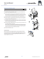
Service Manual Service Manual Contents General.......................................................................................................................... 4 Introduction 4 Spare parts and adaptations 4 Fastening with hexagon socket bolts 4 Torque 5 Checks 5 Identifying and repairing faults 5 Seat................................................................................................................................ 6 Seat width (SB) 6 Seat depth (ST) 6 Sitzhöhe hinten (SHh) 6 Rear seat-to-floor height (SHh) 6 Rear seat height adjustment – Low impact system 7 Rear seat height adjustment – without Low impact system 7 Tipping point adjustment 8 Front seat-to-floor height (SHv) 10 Backrest....................................................................................................................... 11 Backrest height (RH) 11 Backrest height adjustment 11 Backrest angle 13 Backrest angle adjustment 13 Footrests..................................................................................................................... 14 Knee-to-heel length (UL) 14 Footrest replacement 14 Footrest height adjustment 14 Footrest mounted in high position 15 Footplate angle adjustment 15 Side parts.................................................................................................................... 16 Clothes guard / Mudguard 16 Clothes-guard assembly 16 Mudguard assembly 17 Siderest 17 Siderest assembly and adjustment 17 Front wheels................................................................................................................ 18 Front wheel replacement 18 Front fork replacement 18 Rear wheels................................................................................................................. 19 Control of rear wheel parallelism 19 Rear wheel axle replacement 20 Brakes.......................................................................................................................... 21 Parking brakes assembly and adjustment 21 Options & accessories................................................................................................ 22 Antitipper assembly and adjustment 22 3 © Küschall AG, Schweiz | 2011-07 Service Manual General Introduction This Service Manual contains all the technical information necessary for the inspection, configuration or repair of a Küschall® wheelchair. To maintain the necessary levels of safety and reliability, every wheelchair must be thoroughly examined once a year. Some aspects of the assembly and configuration of the wheelchair require a high level of expertise. These assembly instructions therefore break the various tasks down into three categories: Requirement Symbol Easy – technical understanding required Medium – technical knowledge required Difficult – technical knowledge and expertise in assembling wheelchairs required SB The required tools and their sizes are listed before the instructions. The various torque values with which the nuts are to be tightened are also specified in the instructions. A torque spanner must be used, in order to comply with the specified torque values. Tool Symbol Allen key à 3, 4, 5,8 Open-end spanner Socket spanner/Box spanner 8, 10 8, 10 GB Spare parts and adaptations All spare parts may be obtained from the Küschall® customer service department. An electronic spare parts catalogue can be found at www.kueschall.com. Only original spare parts may be used. The written authorisation of Küschall® AG must be obtained before installing additional adaptations on a Küschall® wheelchair. Fastening with hexagon socket bolts Hexagon socket bolts are not designed to withstand an excessive application of force. When tightening or undoing a hexagon socket bolt, force must be applied to the nut wherever possible to avoid damaging the bolt. Tightening and undoing Turn the nut using a socket spanner (only use an open-end spanner if there is insufficient space), using the Allen key simply to stop the bolt turning. Tightening and undoing when no nut is present If a hexagon socket bolt is screwed directly into a thread, the bolt must be tightened using the Allen key. Ensure that the Allen key is of good quality i and not worn. 4 © Küschall AG, Schweiz | 2011-07 Service Manual Torque All bolts must be tightened with the torque specified in the following instructions. Checks Visual check Check the entire frame for cracks, especially in the vicinity of joints and weld seams. Check of the bolts Check that all bolts have been tightened with the torque specified in the instructions. Several bolts are secured with adhesive. If these are loosened, they have to be cleaned and j secured with adhesive again. Self-locking nuts and screws, once loosened, have to be replaced by new ones. j Identifying and repairing faults Fault The wheelchair does not travel in a straight line The wheelchair tips too easily The brakes are gripping poorly or asymmetrically Possible cause Action Incorrect tyre pressure on one rear wheel Correct tyre pressure One or more spokes broken Replace broken spoke(s) Spokes tightened unevenly Front wheel bearings are dirty or damaged Rear wheels are not parallel Backrest angle too large Wrong seat position Incorrect tyre pressure in one or both rear tyres Brake setting incorrect Tighten loose spokes Tyre pressure in rear tyres is too low Correct tyre pressure Rear wheels are not parallel The rolling resistance is very Front wheel axles are restrained by dirt high or hair Bearings are dirty or faulty The front wheels wobble Too little tension on the clevis pin when moving fast housing The front wheel is stiff or Bearings are dirty or faulty stuck 5 Clean or replace the bearings Make rear wheels parallel Reduce backrest angle Change seat position Correct tyre pressure Correct brake setting Make rear wheels parallel Clean front wheel axles Replace the bearings Tighten the nut on the castor fork slightly Replace the bearings © Küschall AG, Schweiz | 2011-07 Service Manual Seat Seat Seat width (SB) Available seat widths: SB 34 to SB 44, in 20 mm steps. Once it has been set the seat width cannot be modified easily. It requires replacing the seat module, backrest, axle and footrest. This modification is not described in the Mentor. Seat depth (ST) Available seat depths: ST 37.5 to ST 47.5 in 25 mm steps. Adjusting the seat depth requires replacing the entire seat module including seat upholstery and rail, as well as the seat cushion. Rear seat-to-floor height (SHh) Available rear seat heights: SHh 40 to SHh 49 in 10 mm steps. To adjust the rear seat height it is necessary to change the rear suspension configuration of the spring (or fixed connection piece) and distance rings, Chap. Seat; ‹Rear seat height adjustment with/without „Low-Impact-System“›. The following configurations are possible: Rear seat-to-floor height by rear wheel size SHh with ‹low impact system› 24‘‘ wheel 25‘‘ wheel without ‹low impact system› 24‘‘ wheel 25‘‘ wheel 40 — — S1 — 41 — — S2 S1 42 — — S3 / M1 S2 43 1 — M2 S3 / M1 44 — 1 M3 / L1 M2 45 2 — L2 M3 / L1 46 — 2 L3 / XL1 L2 47 3 — XL2 L3 / XL1 48 — 3 XL3 XL2 49 — — — XL3 6 © Küschall AG, Schweiz | 2011-07 Service Manual Seat Rear seat height adjustment – Low impact system 3 à 7 Nm 1 3 7 4 1 5 6 7 2 2 Difficulty: Tool: Ã5,8 Loosen the bolts and remove bolt . Lift up the seat module and remove the spring , rubber and distance rings (if fitted). Insert spring , rubber and distance rings according to the required seat height, Table ‹Rear seat-to-floor height by rear wheel size (SHh)›. Turn the clamp on the seat module against the spring unit, until all parts fit together. Fasten the spring unit with the bolt (with adhesive). Make certain to use the correct bolt length, Table ‹Rear seat-to-floor height by rear wheel size (SHh)›. Tighten the bolts . Rear seat height adjustment – without Low impact system 4 1 à 7 Nm 4 1 5 7 6 7 3 3 2 2 Difficulty: Tool: Ã5,8 Loosen the bolts and remove bolt and rings (if fitted). Lift up the seat module and remove the seat-to-frame connection and the distance rings (if fitted). Insert seat-to-frame connection , with or without the distance rings , according to the requested seat height, Table ‹Rear seat-to-floor height by rear wheel size (SHh)›. Turn the clamp on the seat module against the seat-to-frame connection, until all parts fit together. Fasten the seat-to-frame connection with the bolt (with adhesive). Slide 1 or 2 rings onto the bolt if necessary, Table ‹Rear seat-to-floor height by rear wheel size (SHh)›. Tighten the bolts . 7 © Küschall AG, Schweiz | 2011-07 Service Manual Seat Tipping point adjustment The tipping point of the wheelchair can be adjusted by changing the horizontal position of the seat module. à 7 Nm 1 à 7 Nm 3 à 7 Nm 2 à 13 Nm 6 4 5 7 Making it easier to tip the wheelchair Tool: à 4 Difficulty: Loosen bolts . Remove bolts (=4 bolts that connect the rear brace and the seat module ). Move the rear brace forward and use the bolts to secure it in the required position. Remove bolts (=4 bolts that connect the front brace and the seat module ). Move the front brace forward and use the bolts to secure it in the required position. Retighten the bolts . Making it more difficult to tip the wheelchair Tool: à 4 Difficulty: Loosen bolts . Remove bolts (=4 bolts that connect the front brace and the seat module ). Move the front brace backwards and use the bolts to secure it in the required position. Remove bolts (=4 bolts that connect the rear brace and the seat module ). Move the rear brace backwards and use the bolts to secure it in the required position. Retighten the bolts . Additional positions can be set by turning the front brace . In this case, i the fastening elements must be moved. When tightening the fastening elements , it must be ensured that the j slots in the fastening elements are parallel to one another and that the distance of both fastening elements from the centre part is identical. 8 © Küschall AG, Schweiz | 2011-07 Service Manual Seat Seat position and tipping point Seat position (1=rearmost, 6=frontmost seat position) Dimension x Front brace Rear brace (the larger the value of x, the easier it is to tip the wheelchair) (1=frontmost, 4=rearmost position of brace at seat module) (1=frontmost, 5=rearmost position of brace at seat module) Bracket distance Brace distance (=distance between brackets of front brace) (=distance between rear brace and front brace) 1 154 1 1 small 190 2 131 2 2 small 190 3 108 3 3 small 190 4 85 4 4 small 190 3 108 1 3 large 236 4 85 2 4 large 236 5 62 3 5 large 236 6 39 4 5 large 213 54 32 1 4 9 3 2 1 © Küschall AG, Schweiz | 2011-07 Service Manual Seat Front seat-to-floor height (SHv) The front seat height is variable between SHv 48 and SHv 51 (± 10 mm). The front seat height cannot be adjusted independently; it is dependent on the rear seat to floor height, the rear wheel size, the front wheel size, the front fork size and the position of the front wheel within the front fork. It can also be varied by altering the tipping point and the seat angle. The following combinations of front and rear wheels are possible: 75° A B C 3'' 4'' 5'' D E F 24 25 90° Front and rear wheel combination Rear wheel 24’’ 25’’ Frame Front wheel 3'' 4'' 5'' 75° D C B 90° B A — 75° E D C 90° C B — Only choose wheel and axle combinations specified in the table to i ensure that the frame is straight and the axis of the front wheel fork is perpendicular to the ground. 10 © Küschall AG, Schweiz | 2011-07 Service Manual Backrest Backrest Backrest height (RH) To adjust the backrest height, either adjust the push handles (or telescopic tubes) or replace the backrest tube. Suitable backrest tubes and push handles per backrest height RH Without push handles Standard push handles Foldable push handles Cover 27 S S S S S S S 28.5 S S S S S S S 30 S S S S S S S 31.5 S S S S S S M 33 L S S S L S M 34.5 L M L S L S M 36 L M L S L S M 37.5 L M L S L S L 39 L M L S L M L 40.5 L M L L L M L 42 L L L L L M L 43.5 L L L L L M L 45 L L L L L M L 46.5 L L L L L M L Backrest height adjustment A Adjustment of the push handles or telescopic tubes Difficulty: Tool: à 3 8 1 A without push handles Remove the backrest cover. Locate the spring clips inside the backrest straps then press them into the tube. Adjust the telescopic tube to the required height and let the spring clips snap into the nearest holes. Replace the backrest cover. B with push handles B Remove the backrest cover. Slide the backrest strap either up or down to locate the fixing bolt . Remove nut and bolt from both sides. Adjust the push handle to the required height then fit the bolts into the nearest holes and secure with the nuts. Replace the backrest cover. If the required height is not achieved, replace either the push handle, i the telescopic tube or the backrest tube. 11 2 © Küschall AG, Schweiz | 2011-07 Service Manual Backrest Replacement of backrest tube Difficulty: Tool: à 4, 8, 10 Remove the backrest cover. Slide the backrest strap either up or down to locate the fixing bolt . Remove nut and bolt from both sides. Remove the push handles and the upper adjustable backrest straps. If the wheelchair is fitted without push handles, remove the telescopic tubes and the upper adjustable backrest straps by pressing the spring clips into the tube and then pulling the tubes out of the backrest. Remove the bolts securing the backrest tube to the seat module. Remove the lower adjustable backrest straps and the sleeve with the 1 2 stop bolt from the backrest tube . Assemble the lower adjustable backrest straps and the sleeve with the stop bolt to the new backrest tube then secure the backrest tube to the seat module with the bolts . Replace the upper adjustable backrest straps and the push handles and secure with the bolts and nuts. 3 If the wheelchair is fitted without push handles, replace the telescopic tubes and the upper adjustable backrest straps by pressing the spring clips into the tube and then sliding the tubes to the required position until the spring clips snap into the nearest holes. 4 Replace the backrest cover. Functional check: With the backrest in the upright position, check the adjustment of the backrest stop bolt . The bolt head may only slightly touch the seat module when the backrest clicks into its upright position. Adjust if necessary by loosening the lock nut and moving the stop bolt either in or out as required. Tighten the lock nuts. 12 5 © Küschall AG, Schweiz | 2011-07 Service Manual Backrest Backrest angle To adjust the backrest angle re-position the eccentric plate in the backrest joint. The following angles can be set (in relation to the seat): Angle: 74° 78° 82° 86° 90° Setting: Backrest angle adjustment Difficulty: Tool: à 3, 10 Fold the backrest onto the seat and loosen the lock nut of the stop bolt 2 . Tighten the adjustment bolt completely. Remove the bolt of the eccentric plate . Remove the eccentric plate and reinsert it in the required position. 1 3 Verify that both eccentric plates are in the same position. j 4 Reinsert bolt and tighten. Unfold the backrest to the upright position until the spring pins engage in the eccentric plate. Loosen the stop bolt until it slightly touches the frame and the backrest joint no longer has any free movement. Tighten the lock nuts. Functional check: Unfold the backrest.The spring pins must lock into the hole in the eccentric plate. 13 © Küschall AG, Schweiz | 2011-07 Service Manual Footrests Footrests Knee-to-heel length (UL) The footrest must be attached in a higher or lower position to adjust the knee-to-heel length (UL). The UL can be adjusted from 39 cm to 46 cm. For shorter knee-to-heel lengths a high mounted footrest must be fitted, Chap. Footrests; ‹Footrest mounted in high position›. Footrest replacement Difficulty: Tool: à 4, 8 Remove the bolts on both sides of the frame. Remove the footrest from the frame and insert the new one. Replace the bolts on both sides of the footrest and tighten. 1 Footrest height adjustment Difficulty: Tool: à 4, 8 The footrest height can be adjusted in 10 mm steps. à 4 Nm Remove the bolts on both sides of frame. Slide the tube into the correct position. Replace the bolts on both sides of the footrest and tighten. 1 The footrest must be firmly attached in the frame tube. A highmounted footrest may be required if the knee-to-heel length cannot be achieved with the standard footrest. j 14 © Küschall AG, Schweiz | 2011-07 Service Manual Footrests Footrest mounted in high position Difficulty: Tool: à 4, 3 8 1 Slide the frame connector for the high-mounted footrest into the 2 frame and attach with bolt on both sides. 2 Fasten the clamp set with bolt to both sides of the frame, tighten slightly. 1 Slide the high-mounted footrest in the clamp set to the required height. Tighten bolt . à 4 Nm 5 4 Footplate angle adjustment Difficulty: Tool: à 4, 10 The footplate angle can only be adjusted if the footrest is angle adjustable. Loosen all four bolts until the footplate can be moved. Pivot the footplate to the required position and then tighten the bolts . The footplate must be firmly secured to the wheelchair with no room for movement. j 1 à 13 Nm 15 © Küschall AG, Schweiz | 2011-07 Service Manual Side parts Side parts Clothes guard / Mudguard The standard clothes guard can be replaced by a mudguard. Suitable sizes of clothes-guard / mud guard Rear wheels 24‘‘ 25‘‘ SHh 40 L L 41 L L 42 L L 43 M L 44 M L 45 M L 46 M L 47 M M 48 49 M M M M M L Clothes-guard assembly The clothe-guard fixation piece must be already fitted on the backrest tube. Difficulty: Tool: à 3, 4 1 8 Remove existing clothes guard by removing bolt . Align the clothes-guard to the rear wheel. Locate the required position 3 to fasten the clothes guard to the fixation piece before removing the rear wheels. Fasten the clothes-guard to the fixation piece with bolt . 2 If the seat module fixation piece needs to be replaced, remove the bolt . When unfolded, the tip of the clothes-guard must be below the seat i module and the upper rim must run parallel to the rear wheel. à 4 Nm à 4 Nm 4 5 16 © Küschall AG, Schweiz | 2011-07 Service Manual Side parts Mudguard assembly Difficulty: Tool: à 4, 8 If replacing a clothes-guard with a mudguard, first remove the clothesguard and the bracket attached to the seat module. Remove the rear wheels. Attach the bracket to the seat module and remount the rear wheels. Slightly loosen the three bolts on the adjustment plate and move it along the mounting bracket until the mudguard is in position. The position of the mudguard can also be altered by loosening the 1 nuts and and adjusting the mudguard as required so that it runs parallel to the rear wheel. Tighten the bolts. 4 The distance between the mudguard and wheel must be at least i 20 mm if the wheelchair is equipped with the low impact system. 3 2 à 4 Nm à 7 Nm à 7 Nm à 7 Nm Siderest The standard clothes guard can be complemented with a siderest. A siderest cannot be fitted together with a mudguard. 2 Siderest assembly and adjustment 3 1 If replacing mudguards with siderests, first remove the mudguards and the brackets attached to the seat module. 2 If complementing clothes guards with a siderests, remove only the bracket attached to the seat module. Difficulty: Tool: à 4, 8 4 Remove the rear wheels. Attach the brackets and to the seat module on both sides then fix the connecting tube between the two brackets with the bolts. Slightly loosen the three bolts on the height adjustment bracket then fit the siderest into the bracket . 5 6 With the height adjustment bracket touching the seat module bracket , slide the siderest up or down to the required height then tighten the bolts . 17 © Küschall AG, Schweiz | 2011-07 Service Manual Front wheels Front wheels Front wheel replacement Tool: à 3 Difficulty: Remove the bolts and washers and then remove the front wheel axle . 1 Remove the front wheel . Position the two bushings between the new wheel and fork. 3 1 Guide the front wheel axle through the fork, bushings and wheel , replace and tighten the bolts . 2 à 4 Nm 4 Functional check: 4 The wheel must be secured firmly, but still be able to spin easily. Front fork replacement Difficulty: Tool: 1 2 5 8 4 Remove the bearing block cap by inserting two boltdrivers into the grooves and pushing it upward. Remove the nut and washer . Remove the front fork . 4 Check the ball bearing blocks and replace if necessary. 3 Attach the new front fork with the washer and nut and tighten. Perform functional check (see below). Replace the bearing block cap . Functional check: Tip the wheelchair 90° backwards, so that the chair is lying on the backrest and rear wheels. Turn the fork upwards (position A) and let it tip downwards. The fork is tightened correctly when it turns slightly over the lowest point and stays there (position B). The fork hasn’t been tightened sufficiently if it turns back into the lowest position (position C). If tightened wrongly, there is a possibility for the front wheels to start fluttering at high speeds. A B C 18 © Küschall AG, Schweiz | 2011-07 Service Manual Rear wheels Rear wheels Control of rear wheel parallelism 2 Tool: à 5 Difficulty: Loosen the two bolts that clamp the centrepart to the axle . Remove the wheels then remove the axle protection rings from the ends of the axle (if fitted). Replace the rear wheels. Remove one of the rear wheels slightly to create a gap between the axle and the hub of the rear wheel, wide enough for a spirit level. Hold the spirit level against the flat part at the end of the axle . This flat must be exactly vertical, if adjustment is necessary it can be achieved by turning the axle within the centrepart . Drehen Sie das Achsrohr im Centerpart bis die Fläche exakt vertikal ist. Tighten the two centrepart bolts , then replace the axle protection 3 1 rings (if fitted). Replace the rear wheels. check the track of the wheels by measuring distances x and y. 5 4 This adjustment must be carried out on a perfectly horizontal i surface. The track of the rear wheel is correct if (measured at height of hub) the distance between the rear wheels is the same at the front and back (x=y). 19 à 7 Nm © Küschall AG, Schweiz | 2011-07 Service Manual Rear wheels Rear wheel axle replacement A new axle has to be fitted if a different rear wheel camber is required. Tool: à 5 Difficulty: Remove the antitipper (if fitted), Chap. Options and accessories; ‹Antitipper assembly and adjustment›. A Remove the rear wheels and the axle protection rings (if fitted). Remove the two bolts that clamp the centrepart to the axle . Remove the axle by sliding it out of the centrepart . It may be necessary to gently prise the centrepart apart slightly with i a boltdriver to remove or replace the axle without scratching it. This 2 must be done very carefully to prevent cracking the coating of the centrepart. Slide the new axle into the centrepart . The centrepart must be 3 approximately in the middle of the axle and the two flats at the ends of the axle must be vertical. Loosely replace the two bolts , then replace the rear wheels. 4 Check that the axle is exactly in the middle by measuring the distance from the inside of the wheel to the edge of the seat module (distance A). Both sides must have the same measurement. If adjustment is necessary, slide the axle to the appropriate side. Check that the rear wheel parallelism is correct by referring to control of rear wheel parallelism, Chap. Rear wheels; ‹Control of rear wheel parallelism›. 2 1 5 à 7 Nm Tighten the two centrepart bolts . Replace the axle protection rings (if fitted) The bore of the axle protection ring is slightly larger at one end to i make it easier to fit it to the end of the axle. Replace the antitipper (if fitted). 20 © Küschall AG, Schweiz | 2011-07 Service Manual Brakes Brakes Parking brakes assembly and adjustment Tool: à 5 Difficulty: 2 The parking brakes must be readjusted after alterations to the rear j wheels are made or the axle is changed. Ensure sufficient air is in the tyres. Loosen the hexagon socket bolt holding the brake assembly to the frame clamp . Slide the brake assembly to the required position and tighten the hexagon socket bolt . i The brake is adjusted correctly if the distance between the wheel and brake shoe is 25 mm when the brake is disengaged. When engaged the brake shoe may not sink into the tyre more than 4 mm. 3 à 13 Nm 1 4 Visual check Check that the parking brakes are positioned correctly. The brake is set correctly if the brake shoe depresses the tyre by no more than 4 mm when the brake is applied. (In the case of active brakes and standard brakes this will be the case when the brake shoe is approx. 25 mm away from the tyre when released.) Functional check Place a weighted wheelchair with parking brake engaged facing uphill and then facing downhill on a ramp with an incline of 7°. The wheelchair may not move. 21 © Küschall AG, Schweiz | 2011-07 Service Manual Options & accessories Options & accessories Antitipper assembly and adjustment 5 Tool: à 5 Difficulty: 2 Remove the existing (short) pivot pin and replace with the longer 1 pivot pin . (Please note that the pivot pin is secured with strong adhesive.) Loosely assemble the 2 parts of the clamp onto the axle with the 6 4 bolts . Slide the clamp as close as possible to the centerpart and onto the pivot pin . 7 3 The pivot pin must be fully engaged in the clamp to prevent the j antitipper from turning on the axle. Tighten the bolts . Slide the antitipper onto the clamp and secure with the QuickPin . Adjusting the height of the antitipper The height of the antitipper can be adjusted by pressing the spring 8 pin and sliding the inner part of the antitipper to the required position until the spring pin locates in the correct hole. Function check: The distance between the antitipper and the ground must be 40 - 60 mm. It must be easy to fold up the antitipper. Tip the wheelchair backwards using the antitipper until the axle is perpendicular to the antitipper’s point of contact with the ground. In this position, the distance between the rear wheel and the ground must be at least 50 mm. x x 50 mm 22 © Küschall AG, Schweiz | 2011-07 Küschall AG Benkenstrasse 260 CH-4108 Witterswil [email protected] www.kueschall.com Service Manual R33 ENGLISH | 2011-07 küschall® distributors Belgium & Luxemburg: Invacare nv • Autobaan 22 • B-8210 Loppem Tel: (32) (0)50 83 10 10 • Fax: (32) (0)50 83 10 11 • [email protected] Danmark: Invacare A/S • Sdr. Ringvej 37 • DK-2605 Brøndby Tel: (45) (0)36 90 00 00 • Fax: (45) (0)36 90 00 01 • [email protected] Deutschland: Invacare Aquatec GmbH • Alemannenstraße 10 • D-88316 Isny Tel: (49) (0)75 62 7 00 0 • Fax: (49) (0)75 62 7 00 66 • [email protected] Deutschland: Ulrich Alber GmbH • Vor dem Weissen Stein 21 • D-72461 Albstadt-Tailfingen Tel: (49) (0)74 32 2006 0 • Fax: (49) (0) 74 32 2006 299 • [email protected] European Distributor Organisation: Invacare • Kleiststraße 49 • D-32457 Porta Westfalica Tel: (49) (0)57 31 754 540 • Fax: (49) (0)57 31 754 541 • [email protected] España: Invacare SA • c/Areny s/n • Polígon Industrial de Celrà • E-17460 Celrà (Girona) Tel: (34) (0)972 49 32 00 • Fax: (34) (0)972 49 32 20 • [email protected] France: Invacare Poirier SAS • Route de St Roch • F-37230 Fondettes Tel: (33) (0)2 47 62 64 66 • Fax: (33) (0)2 47 42 12 24 • [email protected] Ireland: Invacare Ireland Ltd • Unit 5 Seatown Business Campus • Seatown Road • Swords • County Dublin – Ireland Tel : (353) 1 810 7084 • Fax: (353) 1 810 7085 • [email protected] Italia: Invacare Mecc San s.r.l. • Via dei Pini 62 • I-36016 Thiene (VI) Tel: (39) 0445 38 00 59 • Fax: (39) 0445 38 00 34 • [email protected] Nederland: Invacare BV • Celsiusstraat 46 • NL-6716 BZ Ede Tel: (31) (0)318 695 757 • Fax: (31) (0)318 695 758 • [email protected] • [email protected] Norge: Invacare AS • Grensesvingen 9 • Postboks 6230 • Etterstad • N-0603 Oslo Tel: (47) (0)22 57 95 00 • Fax: (47) (0)22 57 95 01 • [email protected] • [email protected] Österreich: Invacare Austria GmbH • Herzog Odilostrasse 101 • A-5310 Mondsee Tel.: (43) 6232 5535 0 • Fax.: (43) 6232 5535 4 • [email protected] Portugal: Invacare Lda • Rua Estrada Velha • 949 • P-4465-784 Leça do Balio Tel: (351) (0)225 1059 46/47 • Fax: (351) (0)225 1057 39 • [email protected] Sverige & Suomi: Invacare AB • Fagerstagatan 9 • S-163 91 Spånga Tel: (46) (0)8 761 70 90 • Fax: (46) (0)8 761 81 08 • [email protected] • [email protected] Switzerland: Invacare AG • Benkenstrasse 260 • CH-4108 Witterswil Tel.: (41) (0)61 487 70 80 • Fax.: (41) (0)61 487 70 81 • [email protected] United Kingdom: Invacare Limited • Pencoed Technology Park, Pencoed, Bridgend CF35 5HZ • Switchboard Tel: (44) (0)1656 776 200, Fax: (44) (0)1656 776 201 • Customer services Tel: (44) (0) 1656 776 222 • Fax: (44) (0) 1656 776 220 © Küschall AG, Schweiz | 2011-07