1
O P T I M I Z I N G
S Y S T E M
MARK II
version 1.2
USER'S GUIDE
960412
1
TABLE OF CONTENTS
1 INTRODUCTION ................................................................ 2
1.1 THE KEYBOARD .............................................................. 3
1.2 INPUTTING VALUES .......................................................... 4
2 BASIC FUNCTIONS ............................................................. 5
2.1
2.2
2.3
2.4
2.5
2.6
2.7
2.8
2.9
THE SCREEN ................................................................
ACTIVATION ................................................................
DEACTIVATION ..............................................................
CHOICE OF CONTROL MODE ....................................................
CONSUMPTION LIMIT .........................................................
CHANGE LIMIT ..............................................................
AUTO LIMIT ................................................................
CONTROL ON DEEP WATER .....................................................
STEP UP/DOWN ..............................................................
5
7
7
8
8
8
9
9
9
3 CONTROL MODES .............................................................. 10
3.1
3.2
3.3
3.4
3.5
3.6
3.7
SPEED MODE ...............................................................
CONSUMPTION (L/NM) MODE ..................................................
CONSUMPTION (L/H) MODE ...................................................
POWER (KW) MODE ..........................................................
POSITION/ARRIVAL MODE ....................................................
DISTANCE/ARRIVAL MODE ....................................................
AUTOMATIC CALCULATION OF THE TIME OF ARRIVAL .............................
10
11
11
11
12
14
15
4 ROUTE PLANNING ............................................................. 16
4.1 THE ROUTE PLANNING MENU ..................................................
4.2 ROUTE ACTIVATION .........................................................
4.2.1 THE ROUTE KEY ........................................................
4.3 THE ROUTE PLAN IN OPERATION ..............................................
4.3.1 GENERAL ..............................................................
4.3.2 SWITCHING ROUTE LEG ..................................................
4.3.3 MANUAL SPEED CORRECTIONS .............................................
4.3.4 IMPORT ROUTE PLANS AND WAYPOINTS .....................................
16
16
17
18
18
18
18
18
5 MORE ....................................................................... 19
5.1
5.2
5.3
5.4
5.5
5.6
MARKING FOR PRINTOUT .....................................................
MENU .....................................................................
SIMULATION ...............................................................
DISTANCE RECORDERS .......................................................
LOGGING DATA FROM THE VOYAGE .............................................
ERRORMESSAGES DURING OPERATION ...........................................
19
19
20
20
21
21
2
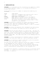
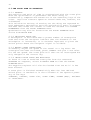
1 INTRODUCTION
SEAPACER is an advanced tool for controlling the speed of a vessel
in an optimal way with respect to its economy and navigation
between destinations.
During operation any of a number of operational modes may be
selected:
SPEED
L/NM
L/H
POWER
POS/ARR
DIST/ARR
ROUTE
Fixed speed.
Fixed fuel consumption per nautical mile (l/nm ).
Fixed fuel consumption per hour (l/h).
Fixed power from engine.
Adapt speed to planned arrival and waypoint.
Adapt speed to planned arrival and distance.
Describe which mode to use at what time during
the voyage. The alternation between modes is done
automatically by SEAPACER.
SEAPACER automatically optimizes the speed distribution between
the route legs. Legs with different depth and/or weather
conditions will then run at different speeds in order to minimize
the total fuel consumption.
SEAPACER minimises the momentary fuel consumption by maintaining
an optimal ratio between the propeller's pitch and speed of
rotation.
SEAPACER controls the main engines in a gentle way. One may, for
instance, limit the speed by which acceleration and retardation is
done. This causes the main engines to operate more smoothly than
when run manually, and thereby avoiding unnecessary rapid termic
changes in the load. The load limits set in the loadregulator are
never exceeded.
SEAPACER is easily configurated for different types of connected
equipment and individual needs by a user friendly menu system.
SEAPACER has an extensive graphics mode which gives the operator
on line curves with speed, fuel, trim etc.
The data from the vessel's operation during the transit is stored
in the SEAPACER for later analysis on the connected PC.
Various kinds of lists and charts can be produced, enabling for
instance long term analysis, comparative evaluations before and
after a reconstruction, maintainance at the shipyard, etc.
For educational purposes, a simulation function is provided inside
SEAPACER. It is built up around similar parameters to those of
the vessel in question.
3
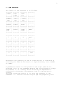
1.1 THE KEYBOARD
The layout of the keyboard is as follows:
+------+
¦SPEED ¦
¦
¦
+------+
+------+
¦POWER ¦
¦(KW) ¦
+------+
+------+
¦ROUTE ¦
¦
¦
+------+
+------+
¦HAN- ¦
¦DLE
¦
+------+
+------+
¦CONS ¦
¦L/NM ¦
+------+
+------+
¦ POS/ ¦
¦ ARR ¦
+------+
+------+
¦LIMIT ¦
¦
¦
+------+
+------+
¦PRINT ¦
¦
¦
+------+
+------+
¦CONS ¦
¦L/H
¦
+------+
+------+
¦ DIST/¦
¦ ARR ¦
+------+
+------+
¦AUTO ¦
¦
¦
+------+
+------+
¦SIMU- ¦
¦LATE ¦
+------+
+------+
¦
¦
¦
¦
+------+
+------+
¦
¦
¦
¦
+------+
+------+
¦
_ ¦
¦
¦
+------+
+------+
¦MENU ¦
¦
¦
+------+
+------+
¦ 7
¦
¦
¦
+------+
+------+
¦ 4
¦
¦
¦
+------+
+------+
¦ 1
¦
¦
¦
+------+
+------+
¦ <- ¦
¦
¦
+------+
+------+
¦ 8
¦
¦
¦
+------+
+------+
¦ 5
¦
¦
¦
+------+
+------+
¦ 2
¦
¦
¦
+------+
+------+
¦ 0
¦
¦
¦
+------+
+------+
¦ 9
¦
¦
¦
+------+
+------+
¦ 6
¦
¦
¦
+------+
+------+
¦ 3
¦
¦
¦
+------+
+------+
¦ .
¦
¦
¦
+------+
+------+
¦CE/C ¦
¦
¦
+------+
+------+
¦ N
¦
¦
¦
+------+
+------+
¦ Y
¦
¦
¦
+------+
+------+
¦ ENT ¦
¦
¦
+------+
Henceforth the pressing of one of these buttons is indicated by
enclosing the name of the button in angle-brackets, thus <SPEED>
or <ENT>.
A pushbutton switch is also placed on the right side of the
keyboard. This is the "CONTROL SWITCH" and should normally always
be pressed. It is a safety switch which may be depressed to
electrically disconnect the Seapacer from all rpm and pitch
control.
The bulb inside the switch is lit when the Seapacer is "IN
CONTROL" i.e. controls the main engine rpm and propeller pitch.
4
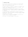
1.2 INPUTTING VALUES
For all input of values from the keyboard the following apply:
Answer questions appearing at the bottom line of the screen.
Submit the input by pressing <ENT>.
By pressing <ENT> as a response to a question, the default value
already in the "answer area" is submitted to the system. This
value is often a "sensible" choice.
A mistyped digit or character can be erased by the <- button.
Pushing <CE/C> once while typing an answer to a question erases
all input typed so far. Pushing <CE/E> twice cancels the question
all together.
It is also possible in dubious cases, to cancel all buttons
pressed so far, even in the middle of a question or while feeding
in new values. The question area on the screen disappears after
approximately thirty seconds.
To answer "yes or no"-queries from SEAPACER, use the keys <Y>
(Yes) or <N> (No) followed by the <ENT>.
User input in this manual appears in bold style.
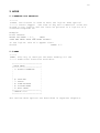
5
2 BASIC FUNCTIONS
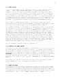
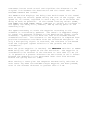
2.1 THE SCREEN
The SEAPACER is normally always in CONTROL MODE. In this mode it
can be told to control the speed of the vessel, and the automatic
logging of data from the voyage takes place.
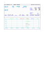
In CONTROL MODE the picture on the next page is on the screen.
An annotated picture is inclued in the beginning of this document.
The screen is divided into two parts; the upper showing measured
signals and input set values, and the lower part showing a sweep
diagram with speed, fuel, rpm etc.
The large digits over the "SPEED BT"-text show the bottomtracksignal from the log. The digits over the "SPEED WT"-text show the
water-track speed, if such a signal is connected. An estimated
value for the current (+0.5) is shown on the mid line. A positive
value signifies that the current has the same direction as the
ship.
The value for CONS L/NM shows the consumption of oil per nautical
mile. The water-track log signal is, if connected, used in the
calculation of L/NM.
The sampled values shown in the mid row on the screen may vary
somewhat depending on which measuring-instruments that are
connected to the SEAPACER-system.
If there is no power-meter connected an estimated value is shown.
The size of the slip is an estimated value since no instrument
measuring the pitch of the propeller is connected.
The digits over the text "CORR" show the "correcting"-signals for
the propeller-pitch for starboard and port (port to the left). A
zero corresponds to an uncorrected pitch. Increasing values
signify a damped pitch in relation to the parameters set for the
load-controller. While pitch-optimizing the values will vary
slowly. A minus ("-") between the values for starboard and port
conveys a decreasing correction (increasing pitch) while a plus
("+") signifies an increasing correction (decreasing pitch). An
optimal level is found when neither a plus or a minus appears.
The CORR fields are left blank when in "HANDLE MODE" i.e when the
Seapacer is not in control.
6
7
2.2 ACTIVATION
The controlfunction of the SEAPACER can be activated only after
both the "WH Control Handles" are above handle-level 5.5 and the
"Controlswitch" is in the ON (in) position.
Note that depending on the shape of the combinatorcurve , the area
for pitch-control may be limited if the handles are not in the
"full ahead"-position while SEAPACER is in control.
SEAPACER is activated by selecting one of the following controlmodes:
+-----+ +-----+
+-----+
+-----+
+-----+
+-----+
¦SPEED¦ ¦CONS ¦
¦CONS ¦
¦DIST/¦
¦POS/ ¦
¦POWER¦
¦
¦ ¦L/NM ¦
¦L/H ¦
¦ARR ¦
¦ARR ¦
¦(KW) ¦
+-----+ +-----+
+-----+
+-----+
+-----+
+-----+
Answer the questions and press <ENT>. See below for a more
detailed description of each control-mode.
That the SEAPACER has control
headline such as "SPEED MODE"
inside the controlswitch. In
fuelconsumption is written in
is signalled both by having a
, and by turning on the small lamp
addition the desirable speed and
a dark green colour.
2.3 DEACTIVATION
SEAPACER can be deactivated in several ways:
• With the HANDLE-button .
+------+
The ¦HANDLE¦ -button should normally be used to ensure a
+------+ controlled transition to manual mode.
Press <HANDLE>. Put the manoeuvring handles into the designated
position. Press <Y> and then <ENT>.
• With the WH Control Handles.
The SEAPACER is immediately deactivated by pulling the WH Control
handles under level 5.The SEAPACER will remain deactivated until
activated, even if the handles are taken above this level again.
• With the Controlswitch
Put the controlswitch in OFF (out) -position. The light inside the
controlswitch will then be turned off.
• Disconnect Seapacer mains power
Disconnect the SEAPACER from the the mains power by switching
off the switch on the front of the central unit.
Note that the all ways but the first may cause a jolt in the main
engines due to a rapid change in the number of revolutions.
The deactivation of the SEAPACER causes the lamp inside the
controlswitch to be turned off, the coloured headline on the
screen to change to read "HANDLE CONTROL", and the dark green
coloured numbers showing the set values for speed and fuel
consumption to disappear.
8
2.4 CHOICE OF CONTROL MODE
For easy use of the SEAPACER, simply choose one of the five
available control-modes: SPEED, CONS L/M, CONS L/H, DIST/ARR or
POS/ARR.
Having chosen a suitable control-mode, press the corresponding
button on the keyboard, and respond to the questions pressing
<ENT> after each response. Failing to press <ENT> will cause the
current control-mode to persist.
The ROUTE-function facilitates automatic alternation between
different control-modes on different parts of the voyage.
2.5 CONSUMPTION LIMIT
A value for the CONSUMPTION LIMIT (L/NM) is requested in controlmodes SPEED, POS/ARR and DIST/ARR.
The significance of this value is as follows. Consumption limit
is given in litres per nautical mile and signifies an upper
ceiling that never should be exceeded. Apart from in rare
transitory cases the SEAPACER never sets a speed that would cause
this ceiling to be violated.
This function allows a maximum, yet safe level of power to be
drawn from the main engines if appropriate values are input. The
operator can input a new value for the limit at any time. If 0
(zero) is given, or if only <ENT> is pushed when CONSUMPTION LIMIT
(L/NM) is requested, there will be no upper limit.
2.6 CHANGE LIMIT
+------+ Change-limit is used to alter the consumption and
¦CHANGE¦ power limits chosen when either of SPEED,DIST/ARR
¦LIMIT ¦ or POS/ARR was selected.
+------+
The following questions appear on the screen:
ENTER CONSUMPTION LIMIT (L/NM) (0 MEANS NO LIMIT):
ENTER LOW POWER LIMIT (KW) (0 MEANS NO LIMIT):
ENTER HIGH POWER LIMIT (KW) (0 MEANS NO LIMIT):
If the given high limit on consumption conflicts with the LOW
POWER LIMIT, the latter is given precedense. That is, CONS L/NM
may be exceeded.
9
2.7 AUTO LIMIT
+------+ AUTO LIMIT is an adaptive function that automatically
¦AUTO ¦ sets the CONSUMPTION LIMIT 2 litres/nautical mile
¦LIMIT ¦ above the actual consumption when a steady state has
+------+ reached. This function prevents instantanous peaks in
the consumption caused by headsea, currentsetting, wind, sudden
large changes in the depth of the sea, etc. If the disturbance is
of a more permanent character the upper limit of consumption will
automatically be increased. The new limit will not, however, be
allowed to exceed the original level of the CONSUMPTION LIMIT.
Auto limit is deactivated after a new control-mode has been
selected by one of the buttons SPEED, DIST/ARR or POS/ARR or when
new limits has been input with the CHANGE LIMIT command.
If a power-reading is available (or the power-level is estimated
on the basis of the fuelconsumption) an automatic adaptation to
the power-limits submitted via the CHANGE-LIMIT-command is also
attempted. The limits are used in an attempt to put a window
around the power needed at the moment to uphold the set speed.
The function will thereby prevent sudden changes in the output of
power caused by arbitrary variations in the conditions at sea.
Lasting changes in the conditions cause the window to be moved
and/or increased to attain the set speed. The window will then,
after a preset period of time stepwise decrease until adapted to
the new conditions that prevail. The original values for LOW
POWER and HIGH POWER are, however, never violated.
For an example, please refer to chapter 3.1.
2.8 CONTROL ON DEEP WATER
On certain routes on deep water, disturbances on the logsignal can
be seen before reaching shallow waters. In SPEED control-mode
this results in great variations in the speed of revolutions to
compensate for imaginary changes in speed. To prevent this the
SEAPACER can be ordered to keep the speed of revolution fixed when
passing deep water stretches. The only control of speed of
revolution allowed is then through CONSUMPTION L/H MODE and POWER
MODE.
This function can be turned on and off in via the menu system;
press <MENU> 8 3 5 5 to change the default value.
2.9 STEP UP/DOWN
The operator may in some circumstances require a very fast speed
reduction or increase. The up-arrow- and down-arrow-keys may be
used for this purpose. They force an rpm/pitch step up or down
corresponding to a fixed percentage of current power outtake (the
percentage is set in the "POWER LIMITS" menu: <MENU> 8 4 7).
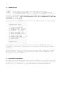
10
3 CONTROL MODES
3.1 SPEED MODE
+-----+ Type the desired speed (knots) and press <ENT>.
¦SPEED¦ This can be combined with an upper limit for the fuel
+-----+ consumption. If no limit is wanted simply press <ENT>
without typing a value. SEAPACER will maintain this speed until a
new command sets a new value, or the given upper limit is reached.
Increases and decreases in speed are always very slow to save fuel
and protect the engines. The command should therefore be given in
good time before the speed is to be reached.
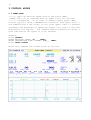
Example:
Press <SPEED>
ENTER REQUIRED SPEED: 18____ <ENT>
ENTER CONSUMPTION LIMIT (L/NM): 100___ <ENT>
Press <AUTO LIMIT>
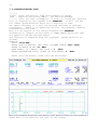
After this command the screen looks as follows:
11
The vessel will now attempt to reach a speed of 18.0 knots, as
long as the limitations on fuel consumption and power output are
not exceeded.
When <AUTO LIMIT> is pressed, three adaptive limits are put into
effect; CONS LIMIT, LOW POWER and HIGH POWER LIMIT.
CONS LIMIT automatically becomes 98 l/nm, that is just below the
set upper limit. This upper limit, 100 l/nm, is shown below the
dynamically set CONS LIMIT.
HIGH POWER LIMIT is assigned the value 8565 hp, that is somewhat
over the actual power level. LOW POWER LIMIT is set to be the
same as the power level stated as the default lowest permissible.
(Refer to separate chapters for more information about the
limits.)
3.2 CONSUMPTION (L/NM) MODE
+----+
¦CONS¦ State the desired fuel consumption in litres per
¦L/NM¦ nautical mile and press <ENT>. The SEAPACER will
+----+ stay at this level of consumption until another command is
issued. A certain variation is allowed to prevent sudden
unmotivated changes in the speed of revolution.
The fuel consumption L/NM is computed from readings from the fuel
meter and the log of the speed through the water if available.
This is a measure of the resistance the vessel is facing while
navigating the sea.
3.3 CONSUMPTION (L/H) MODE
(This mode is replaced by POWER MODE in some installations.)
+----+
¦CONS¦ State the fuel consumption in litres per hour and press
¦L/H ¦ <ENT>. The SEAPACER will stay at this level of
+----+ of consumption until another command is issued. A certain
variation is allowed to prevent sudden unmotivated changes in the
speed of revolution.
3.4 POWER (KW) MODE
+-----+
¦POWER¦ State the desired power in kilowatts and press <ENT>.
¦(KW) ¦ The SEAPACER will maintain this level of power output
+-----+ until another command is issued. A certain variation is
tolerated so as to avoid sudden changes in the speed of revolution
due to attempts to keep the power level constant.
12
3.5 POSITION/ARRIVAL MODE
+----+
¦POS/¦ State the arrival time and the number for the selected
¦ARR ¦ waypoint and press <ENT>. If it desirable to have
+----+ an upper limit on the fuelconsumption (litres per nautical
mile), enter it in response to the request from the SEAPACER. The
SEAPACER will now attempt to use the lowest possible while still
arriving according to schedule.
Example:
Press <POS/ARR>
ENTER TIME OF ARRIVAL (EG: 0805) OR MEAN SPEED: 0002 <ENT>
ENTER WAYPOINT NUMBER: 2 <ENT>
MEAN SPEED: 19 KNOTS. OK? (Y/N) Y <ENT>
ENTER CONSUMPTION LIMIT (L/NM) OR JUST ENTER: 110 <ENT>
The waypoint number are put into one separate register that may be
inspected and modified by the operator. The register can be
accessed by pressing <MENU> <1>:ROUTE PLANNING <6>:WAYPOINT
REGISTER.
If 0 (zero) is typed as an answer to the question "ENTER WAYPOINT
NUMBER", the latitude and longitude are requested by two
questions.
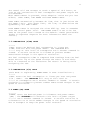
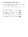
The screen now holds the following picture:
13
CTE means "Cross track error" and signifies the distance to the
original line between the destination and the vessel when the
POS/ARR-command was issued.
The DELAY-field displays the delay that would ensue if the vessel
were to keep the current speed during the rest of the voyage. The
speed is, of course, adjusted in such a way so as to minimise the
delay as much as possible. If the stated limiting values (CONS,
LOW POWER and HIGH POWER LIMIT) combines to inhibit an increase in
the speed, the delay will, however, add up during parts of the
remaining trip.
The speed necessary to reach the waypoint according to the
schedule is continuously updated. The vessel is supposed always
to travel the shortest distance to the destination (great circle
distance). Updating is not done the last five minutes before
scheduled arrival. The distance to the waypoint is computed from
position-information available from the connected navigator. If
only a bad quality signal is received, the distance is estimated
from the logsignal (speed relative to the ground) and time
information.
When the given waypoint is reached, the SEAPACER switches to SPEED
MODE using the last speed as the new set-value. The waypoint is
considered to be reached if the distance is less than 0.5 nm (if
it is passed on a greater distance the set-values is still frozen
because the updating is not performed later than five minutes
before the giving arrival time).
When running a route plan the Seapacer automatically switches to
next route leg when the POS/ARR target waypoint has been passed,
even if the nearest distance is greater then 0.5 nm.
14
3.6 DISTANCE/ARRIVAL MODE
+-----+
¦DIST/¦ State the arrival time and distance to chosen
¦ARR ¦ waypoint and press <ENT>. The desired maximum
+-----+ limit for fuel consumption is given in litres per nautical
mile in response to the request from SEAPACER. It will now use
the lowest speed possible while still arriving in time.
The speed necessary to travel the desired distance is updated
continuosly. There is no updating the five last minutes ahead of
estimated arrival time.
When 0.5 nm remains of the stated distance the SEAPACER
automatically changes control-mode to SPEED MODE, using the last
set speed as the new desired speed.
The distance is computed from the logsignal (speed relative to
ground).
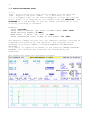
Example:
Press <DIST/ARR>
ENTER TIME OF ARRIVAL (EG: 1805) OR MEAN SPEED: 0020 <ENT>
ENTER DISTANCE IN NM: 40 <ENT>
MEAN SPEED: 18.1 KNOTS. OK? (Y/N)? Y <ENT>
ENTER CONSUMPTION LIMIT (L/NM) OR JUST ENTER: 0 <ENT>
After this the screen looks like the following:
The field DELAY displays the delay that would ensue if the present
speed were to be used for the rest of the voyage.
15
3.7 AUTOMATIC CALCULATION OF THE TIME OF ARRIVAL
If the remaining distance as well as the wanted average speed is
known, the "TIME OF ARRIVAL" must be tried out by repeated inputs.
To simplify this particular application of DIST/ARR and POS/ARR
an automatic procedure has been developed:
If the desired speed is stated as response to the question "ENTER
TIME OF ARRIVAL OR MEAN SPEED", the time of arrival is computed
and is displayed on the screen whereupon it can be accepted by
responding <Y> <ENT>:
Example (fed in at 10:00):
Press <DIST/ARR>
ENTER TIME OF ARRIVAL (EG: 1805) OR MEAN SPEED:20.0 <ENT>
ENTER DISTANCE IN NM: 40 <ENT>
ARRIVAL 12:00 ? (Y/N)? Y <ENT>
ENTER CONSUMPTION LIMIT (L/NM) OR JUST ENTER: 0 <ENT>
Corresponding example with POS/ARR:
Press <POS/ARR>
ENTER TIME OF ARRIVAL (EG: 1805) OR MEAN SPEED:20.0 <ENT>
ENTER WAYPOINT NUMBER: 12 <ENT>
ARRIVAL 13:12 ? (Y/N)? Y <ENT>
ENTER CONSUMPTION LIMIT (L/NM) OR JUST ENTER: 0 <ENT>
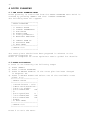
16
4 ROUTE PLANNING
4.1 THE ROUTE PLANNING MENU
Route planning is controlled from the ROUTE PLANNING menu which is
reached by pressing <MENU> and then 1:ROUTE PLANNING.
The following menu will appear:
+-----------------------+
¦ ROUTE PLANNING
¦
+-----------------------¦
¦ 1: SELECT ROUTE
¦
¦ 2: VOYAGE PARAMETERS ¦
¦ 3: RUN ROUTE
¦
¦ 4: ROUTE PLAN
¦
¦ 5: route parameters
¦
¦ 6: WAYPOINT REGISTER ¦
¦
¦
¦ 8: IMPORT FROM PC
¦
¦ 9: OPTIMIZE NOW!
¦
¦ 0: EXIT MENU
¦
+-----------------------¦
¦ CHOOSE 0-9:
¦
+-----------------------+
The route plans should have been prepared in advance on the
connected Seapacer PC.
Refer to "Seapacer PC route optimizer user's guide" for details.
4.2 ROUTE ACTIVATION
A route is activated by the following steps:
1) Press <MENU>
2) Press 1:ROUTE PLANNING
3) Press 8:IMPORT FROM PC if the route plan has been changed
in Seapacer PC.
4) Press 1:SELECT ROUTE and select one of the available route
plans. E.g:
+-----------------------+
¦ SELECT ROUTE
¦
+-----------------------¦
¦ 1:Fredrikshavn - Oslo ¦
¦ 2:Moss Nord-Fredriksh.¦
¦ 3:G-K via Fladen
¦
¦ 4:T-G SPEED/POS
DW¦
¦ 5:
¦
¦ 6:T-G Speed/Pos
H ¦
¦ 7:T-G SPEED/POS
DW¦
¦ 8:T-G SPEED/POS
DW¦
¦ 9:TEST
¦
¦ 0: EXIT MENU
¦
+-----------------------¦
¦ CHOOSE 0-9:
¦
+-----------------------+
Press 0 to exit the menu.
17
5) Press 2:VOYAGE PARAMETERS and enter departure time and
weather conditions.
The route is divided into three parts; A, B and C. (this is
done in the route set up stage performed on the Seapacer PC
and may be viewed in 4:ROUTE PLAN from the ROUTE PLANNING
in Seapapcer PC).
menu
+-----------------------+
¦ VOYAGE PARAMETERS
¦
+-----------------------¦
¦
PART:
A
B
C ¦
¦ 1:WIND
0.0 3.0 0.0 ¦
¦ 2:DIR.
0 130
0 ¦
¦ 3:CURRENT 0.0 0.0 1.0 ¦
¦ 4:DIR.
0
0 80 ¦
¦
¦
¦ 5:DRAUGHT
5.60 M¦
¦ 6:DEPART. 19:00 940320¦
¦
ARRIVAL 23:00 940320¦
¦ 0:EXIT MENU
¦
+-----------------------¦
¦ CHOOSE 0-6:
¦
+-----------------------+
The speed profile will be computed when you exit by pressing 0.
5) Press 4:ROUTE PLAN to check the resulting speed profile.
6) Press 3:RUN ROUTE to start the route plan or go back to 5)
correct the input values.
to
4.2.1 THE ROUTE KEY
+-----+
¦ROUTE¦
+-----+
The <ROUTE> key gives a faster and easier way to perform the above
described procedure to start a route plan.
Follow the instructions on the screen and update the departure
time, current, draft and wind values.
Exit the menu by pressing 0. The route plan will now be optimized,
i.e. a speed profile will be calculated.
Pressing <ROUTE> while a route plan is running gives the same
result as entering the sequence:
<MENU> <1>:ROUTE PLANNING <4>:ROUTE PLAN
i.e. the current route plan will be listed on the screen.
18
4.3 THE ROUTE PLAN IN OPERATION
4.3.1 GENERAL
The position and point of time is synchronised with the route plan
when the optimization is performed. The exact delay is
automatically computed and evened out on the remaining legs of the
route. Legs with constant speed as control-mode are, however, not
influenced.
This calculation and way of evening out the delay are repeated at
each subsequent switchpoint and also periodically every 10 minutes
and when new values for current or wind are entered in 2:VOYAGE
PARAMETERS from the ROUTE PLANNING menu.
Optimization way also be forced from the ROUTE PLANNING menu
choice 9:OPTIMIZE NOW!
4.3.2 SWITCHING ROUTE LEG
A switchpoint is activated when a preset number of consequtive
read outs from the navigator indicate that the distance to the
switchpoint is increasing. It is therefor important to place the
switch points where the navigator signal is reliable.
4.3.3 MANUAL SPEED CORRECTIONS
To manually adjust the speed of the vessel on a leg after the
route-plan has been activated, press <SPEED> and give a new value
for the set speed. The route plan will then not be interrupted but
only changed on the current leg.
4.3.4 IMPORT ROUTE PLANS AND WAYPOINTS
To fetch all new or modified route plan from the connected
SEAPACER PC computer, select 8:IMPORT FROM PC from the ROUTEPLANNING-menu.
The waypoint-register will also be fetched from the PC if it has
been altered.
A route plan is finished automatically when the last defined
switch point is reached.It is also finished if the operator press
any of the keys
<HANDLE>, <SPEED>, <CONS L/H>, <CONS L/NM>, <POWER (KW)>, POS/ARR>
or <DIST/ARR>.
19
5 MORE
5.1 MARKING FOR PRINTOUT
+-----+
¦PRINT¦ This button is used to mark the loglist when special
+-----+ events happen. The time of day and a numerical value are
stored in the logfile and can later be printed in a loglist on a
connected Seapacer PC.
Example:
Press <PRINT>
ENTER LOG MARK : 2.3__
<ENT>
TIME AND MARK HAVE NOW BEEN STORED!
In the loglist this will appear thus:
081230
MARK: 2.3
5.2 MENU
+----+
¦MENU¦ This key is used get the menu showing all the
+----+ additional functions available.
+-----------------------+
¦ MAIN MENU
¦
+-----------------------¦
¦ 1: ROUTE PLANNING
¦
¦
¦
¦
¦
¦
¦
¦
¦
¦ 6: TESTING
¦
¦ 7: SETUP
¦
¦ 8: CONFIGURATE
¦
¦ 9: SYSTEM MENU
¦
¦ 0: EXIT MENU
¦
+-----------------------¦
¦ CHOOSE 0-9:
¦
+-----------------------+
The various menu options are described in separate chapters.
20
5.3 SIMULATION
+-----+
¦SIMU-¦ This mode can be used for demonstrations and
¦LATE ¦ educational purposes. It can only be invoked while
+-----+ in HANDLE CONTROL, that is when the SEAPACER is not in
control. Different operational conditions and control modes can
now be simulated. No controlsignals will be transmitted from the
SEAPACER in this mode.
By pressing the SIMULATE button the following menu is displayed:
+-----------------------+
¦ SIMULATION SETUP
¦
+-----------------------¦
¦ 1: SIMULATE ON/OFF
¦
¦ 2: WATER DEPTH 100 M.¦
¦ 3: CURRENT 0.5 KNOTS ¦
¦ 4: COURSE
0.0 DEG. ¦
¦ 5: MAIN ENGINES STB 1¦
¦ 6: MAIN ENGINES PORT 1¦
¦ 7: SHAFT GEN STB.
0¦
¦ 8: SHAFT GEN PORT
0¦
¦ 9: TIME CONST. 60 SEC.¦
¦ 0: EXIT MENU
¦
+-----------------------¦
¦ CHOOSE 0-9:
¦
+-----------------------+
The default start values for simulation are shown and may be
altered in the menu. Simulation is turned on and off with menu
choice 1.
During simulation no logging of the actual data from the voyage
will be done. Instead, all simulated values and commands are
stored on logfile number 0.
5.4 DISTANCE RECORDERS
The two distance recorders are reset automatically each time the
propellers start to move. The left one is also reset at start of a
route leg or a manually given DIST/ARR or POS/ARR command.
21
5.5 LOGGING DATA FROM THE VOYAGE
The SEAPACER stores all interesting data sampled. All commands are
also logged. This data can be used later for documentation,
analysis, statistics, and so on.
The logging-interval can be set to any period between one minute
and one hour. In this installation it set to 1 minutes.
The data from each voyage is stored on logfiles consecutively
numbered from 1 and upwards. The logfiles are overwritten in a
rotational way, that is the oldest file is overwritten first. The
maximum number of logfiles is 30.
For comparative analysis from a great number of voyages, the log
files are automatically transferred to the connected PC equipped
with SEAPACER PC, a comprehensive program-system for voyageanalysis and route planning.
5.6 ERRORMESSAGES DURING OPERATION
Errorsituations are indicated by red messages on the screen. They
vanish when the next command is invoked. The following messages
may appear:
ERROR IN CONS. SENSOR:
The signal from the fuel meter was distorted. If it happens
frequently the malfunctioning must be rectified.
Spurious distortions are filtered by SEAPACER and does not affect
operation.
ERROR IN LOG SIGNAL:
The signal from the speed logg was distorted. If it happens
frequently the malfunctioning must be rectified.
Spurious distortions are filtered by SEAPACER and does not affect
operation.
PASSIVE DUE TO RPM MISMATCH:
The propeller speed commanded by SEAPACER and that measured
deviates too much. May be caused by a malfunctioning rpm pickup
or an incorrect calibration in the control system for the
propeller.
In this situation SEAPACER will apply a constant signal to the
main engines.
Weak signal from the navigator is indicated by a question mark in
front of the latitude value. In these cases the POS/ARR cannot be
started. An already initiated POS/ARR leg switches over to
position calculation based on the speed log is is thus not
interrupted.