1
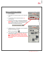
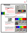
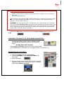
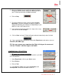
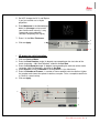
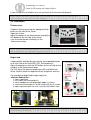
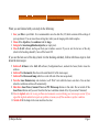
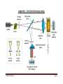
Leica TCS SP5
LASAF New User Guide
This Application Note was created by:
Myriam Gastard, Ph.D.
Leica Application and Technology Support Group, Life Science Division
Exton, PA 19341, USA
Leica Microsystems, Inc. 1
QUICK-START FOR SP5
STARTING YOUR SP5 system:
1- Turn on the laser, scan, and computer/Mic buttons on your console (push
green buttons, turn your laser’s key).
2- Logon to Windows.
3- Double Click on LAS AF icon on your
computer.
4- Click on Start in the LAS AF window.
ACTIVATE YOUR LASERS:
1- Click on the Configuration tab.
2- Click on laser.
1
2
3- Activate the laser(s) needed for your experiment by checking the box(es).
If you do not know which laser(s) to activate, then check every boxes to be sure that the
needed laser(s) will be turned on.
3
If you are using the Argon laser, do NOT forget to put the digital
power slider at 20-30%.
Leica Microsystems, Inc. 2
SETUP for ACQUISITION OF IMAGES:
1- Click on Acquire.
1
2
2- The window will automatically open on the Acquisition
mode.
3
3- The acquisition will be automatically be on xyz
scanning mode.
4
4- The format of your image is automatically displayed in
512x512 pixels. The speed is automatically chosen at
400 Hz and the image size as well as the pixel size is
automatically calculated and displayed.
5
5- Imaging parameters (XY Window) can be changed by
opening the drop-down window.
Click on the arrowhead.
6
6- In the opened XY window, image format and scanning
speed can be changed. We encourage new users
not to change these parameters at first. A better
understanding of your confocal system will allow
you to modify later on scan format and speed when
appropriate.
Leica Microsystems, Inc. 3
1
BEAM PATH SETTINGS:
2
1- Click on Visible to activate the laser(s).
2- Select the laser and their intensity by
moving the sliders up or down (AOTF%,
between 20-30% to begin with).
Choice of the laser line(s) is depending
on the fluorophore(s) your sample is
labeled with.
For instance:
• Alexa 488, FITC or GFP will be excited
using the 488 Argon laser line.
• Alexa 568 is excited using the568 laser
line or the 543 laser line if your system
is not equipped with a 568 laser line.
An active laser line will be expressed as a line
on the spectrum.
3
3- Activate the PMTs (3a) by clicking on the Active button and chose the color for
your fluorophore emission (3b). A gray shadow will then appear underneath the
PMT bar confirming that the PMT is active.
3b
3a
4- Click on None to open the drop-down
window, and choose the fluorophore
emission wavelength. This step will help
you in setting your PMT
In our example: Alexa 488 was chosen for
the PMT1.
5- Place the PMT bars in correspondence
with the fluorophore wavelength by sliding
it left and right. The slider can also
be resized by clicking on the right or left
side of it. Also, double clicking on the
slider will open a window where you can
enter the begin and end position of the
slider
Leica Microsystems, Inc. 4
7- Click on the Live button (lower left corner of your setup screen) to check a live
image of your sample.
8- Turn the Smart Gain knob until you can visualize your signal. If you have more than
1 fluorescence, and then more than 1 PMT activated, your viewer screen (right
monitor) will be separated in 2 halves.
• Click on one half of the viewing screen to select the channel, and adjust your
gain using the Smart Gain knob.
• Then, click on the other half of the screen to select the other channel, and
adjust the gain for this channel using the Smart Gain knob again.
9- Adjust your gain and offset, using the QLUT button (Quick Look Up Table) to
change your image color as intensity values. Set up your intensity as shown below
with few blue (saturated) pixels, most orange and white pixels, and your background
as mostly green pixels (using your Smart Offset button).
Gain
adjustment
Offset
adjustment
Blue = saturated
signal = 255
Gain
adjustment
Black to Orange to
= signal
between 1 to 254
Green = no signal
=0
Click twice on the QLUT button to go back to your original colors.
10- Adjust if necessary the laser intensities (as described in 2) and PMTs bars position
(as described in 5).
Leica Microsystems, Inc. 5
Offset
adjustment
If the image is still too dim or not visible at all:
•
•
Enhance the laser power using the vertical slider (AOTF %) until you can see an image on
the screen.
Adjust the PMT Smart Gain.
PS: A smart gain value lower than 400 V would mean that you can lower the laser power and go
up the smart gain until about 900-1000 V). A smart gain between 1100-1250 would suggest
going up on the laser power (AOTF %).
REMEMBER: By enhancing the AOTF% you will expose your sample to more laser exposition,
hence your sample will bleach faster. On the other hand, enhancing the gain won’t expose your
sample to more laser exposition, and it will protect your sample from too much laser exposition.
Thus, in order to protect your sample signal, it is better to first adjust your gain, and then if not
enough signal is found to enhance your AOTF %.
Click on the Stop button, and then click on the Capture Image button to acquire an
image.
CHANGING THE QUALITY OF YOUR IMAGE ACQUISITION:
1- Averaging the Line number and/or the Frame number
can dramatically enhance the quality of the acquired
image.
1
Acquisition XY window
Under Acquire and Setup, click on the arrows of either Line
and/or Frame buttons and choose the averaging number (for instance 1-4).
ACQUISITION OF A Z-STACK:
1
1- Under the Acquire Tab, go to Acquisition.
2- Click on Scan Modes in the Acquisition Mode and
select xyz.
3- Go to Live Mode.
2
4- Move at the top of your sample (on the Z plan, using the
z-position knob), and set the position of your Z-Stack by
clicking on the Begin arrowhead.
Leica Microsystems, Inc. 6
5- Move at the bottom of your sample (or region of interest,
using the z-position knob), And set the bottom position of
your Z-Stack by clicking on the End arrowhead.
4
6- Click on Stop.
5
7- To set the number of z-steps, you can choosesystem
optimized if you desire to obtain the optimal number of
image calculated for your Z-Stack size (depending on your
objective, zoom and image format).
7
8- If you choose to enter the number of z-steps or the z-step
size then click on Nr. of steps.
8
9-
Click on Start, and your Z-Stack will begin and end automatically when finished.
10- Your z-stack will be automatically saved under Experiment, and under a name as:
Serie001 (56.4 MB, xyz).
PS: You can rename your experiment by Right clicking on the name and
click on “Rename” and then type a new name.
3-DIMENSIONAL PROJECTION:
2
•
3D projection without animation:
After acquiring a z-stack (or series), you can process your data
to a 3-D projection.
1
1- Under Experiment, click on your Series name.
2- Go to Process.
3- Click on Tool.
3
4- In the Process Tools, click under Visualization and
3D Projection, located at the bottom of the list.
4
Leica Microsystems, Inc. 7
5- Do NOT change the X, Y, and Z plans
if you just need to see a simple
projection .
6- Enter Maximum in the Method drop
down list (Average can be used if
your fluorescence intensity is very
strong and a max projection
saturates completely the signal).
7- Enter 1 in the Slice Thickness.
6
8- Click on Apply.
5
7
8
3D projection with Animation:
•
1- Click on Create a Movie.
2- Enter the Start Rotation angle (in degree) corresponding to the start view of the
movie (example: –190, Start Rotation), and click on Set Start.
3- Enter the End Rotation angle (in degree) corresponding the end view of the movie
(example: 190, End Rotation), and click on Set End.
4- Under Options, enter the Method in the drop down list (ex: Maximum).
5- Enter the Number of Frames (= number of frame needed to do the rotation. Higher
the number and slower the speed of rotation; example: 70 for a complete rotation for
a 512x512 z-stack series).
6- Click on Apply.
4
2
1
3
5
3
6
Leica Microsystems, Inc. 8
The 3D movie can be visualized on your right screen.
1- Click the Play (►) button, to begin the movie.
2- Click the Overlay (
) button to visualize both colors.
3- Double click on the overlay image to have the movie full screen.
3- Click on the Stop button to end the movie.
2
3
1
4
Leica Microsystems, Inc. 9
Leica Microsystems, Inc. 10
University of Zurich
3
Center for Microscopy and Image Analysis
2. Mount and focus sample
The microscope:
Controller unit
2.1. Mounting of sample:
Put the slide up-side-down on the stage. If you are using immersion objectives, make
sure you use the appropriate immersion medium and never mix different media. Add
a drop to the objective or coverslip.
2.2. Selection of objective:
Select the objective directly on the scope by pressing the
objective changer buttons or more conveniently by the
software.
.
Note: Check objectives for the proper adjustment of correction collars and make sure
that the cap on the front of the objective is released.
2.3. Focusing your sample:
Start with the 10 x air objective to find the focus and to get an overview
of your sample. Focus your sample by moving the objective up with the
focus wheel or button on the microscope or with the z-drive on the
controller unit. Start in the coarse focus mode and fine tune with the fine
focus mode (toggle button on the controller unit).
Fix the focal plane:
To save your focal plane press button 1 and 2 (see illustration above) on
the right side of the stand together twice. The Z-position is now on 0.
3
University of Zurich
4
Center for Microscopy and Image Analysis
If you change than to another lens you just have to fine tune the focal plane.
Note: Always start with a low magnifying air objective. Be careful when working with
immersion lenses to not run into the sample.
2.4. Illumination:
Fluorescence:
Choose a filter by pressing the appropriate filter
button on the front of the stand.
Open the shutter.
Adjust the power of the fluorescence lamp by the
INT button on the left side of the stand
(see illustration below) or directly on the
fluorescence lamp.
Note: To avoid photobleaching work with an intensity as low as possible and close
the shutter when you stop observing your sample.
Bright field:
Choose bright field light by pressing the corresponding button
on the left side of the stand (BF, DIC, Phasecontrast).
Adjust the brightness with the INT button on the left side of the
stand or at the fluorescence lamp.
For DIC adjust the aperture diaphragm (AP) and Wollaston
Shear Control (wheel on objective turret) for optimal contrast.
For recording of bright field images adjust for
“Koehler illumination”:
1. focus specimen
2. fully close the illumination iris
3. focus condenser until diaphragm edge is in focus
4. move the illumination iris to the center with the 2 screws
5. open up illumination iris until it just fills the field of view
2
3
4
Note: It is always worthwhile to observe your cells in bright field mode to check
whether they are healthy.
4
Only people who have received an introduction from one of the BioVis personal or Stefan
Gunnarson are allowed to operate the system! If you need intro please write
to [email protected] or [email protected].
1. Check the microscope if everything looks clean and normal. If not report it in the logbook.
2. Switch on all the three green buttons marked as PC Microscope, Scanner Power and Laser Power on the
right side under the table are. Switch these on in this order and turn the Laser Emission key 90 degrees
clockwise.
3. Switch on the fluorescent lamp (white box on the left side of the microscope desk).
4. Switch on the thermostat (blue box on the small desk left of the microscope) if you want to do live imaging
with temperature control.
1. Login to the computer with your account.
2. Wait 1 min so the system is fully booted.
3. Click on the LAS AF software icon on the desktop. Shortly you will see the LAS start screen. Check under
configuration that machine is selected. Press OK to start the system.
4. At the end of the starting process it will ask you to initialize the stage. Click YES.
5. Switch on those lasers that you want to use in the LAS AF software under the Configuration\Laser menu.
If you switch on the argon laser put it on 20% always. Note that the 405 and argon lasers need at least 20
minutes warm up time for proper use.
6. The machine is ready to use.
© Matyas Molnar
Page 1
When you are finished with your study do the following:
1. Save your files to your folder. It is recommended to save the data file (.lif) which contains all the settings of
your experiment. You can reuse these settings later when you do imaging with similar samples.
2. Clean all the objectives, the condenser and the stage.
3. Swing in the lowest magnification objective (or empty slot).
4. Close LAS AF software and log-out from your windows account. If you are not the last one of the day
(check in the booking calendar!), leave all the lasers ON.
If you are the last user of the day (check it in the booking calendar), follow with these steps to shut
down the microscope:
5. Switch off all lasers in the LAS AF software (Configuration\Laser, uncheck the boxes) before close the
software.
6. Switch off the thermostat (blue box on the small desk left of the microscope).
7. Switch off the fluorescent lamp (white box on the left side of the microscope desk).
8. Turn the Laser Emission key anti clockwise to off. Wait 5 min while the lasers cool down. You can hear
when the ventilation switches off automatically.
9. Shut down Laser Power, Scanner Power and PC Microscope buttons in this order. Do not switch off the
Laser Power button until you can’t hear that the laser ventilation turned off (or if you waited 5 minutes)!
10. Use the logbook and write in any problems and comments occurred during your microscope session! If you
signed the logbook and did not report any problem, it means you left the machine in perfect condition.
11. Switch off all the lamps in the room and close the door.
© Matyas Molnar
Page 2
Appendix I - Confocal microscopy setup
© Matyas Molnar
Page 3
Appendix II - Leica confocal microscope
1. UV Laser
2. IR Laser
3. Visible range Laser(s)
4. UV AOTF
5. IR EOM
6. Visible range AOTF
7. UV adaptation optics
8. UC excitation pinhole
9. IR excitation pinhole
10. VIS excitation pinhole
11. Primary beam splitter
12. Adjustable pupil illumination
13. "K"-Scanner with rotator
14. Microscope & objective
15. Transmitted light detector
16. Confocal detection pinhole
17. Analyzer wheel
18. Spectrophotometer prism
19. Photomultiplier channel 1
20. Photomultiplier channel 2
21. Photomultiplier channel 3
22. Photomultiplier channel 4
23. External optical port
© Matyas Molnar
Page 4
Appendix III – Using the pinhole
© Matyas Molnar
Page 5
Appendix IV - Laser characterization using the AOTF
© Matyas Molnar
Page 6
Appendix V - Optical resolution of the microscope
© Matyas Molnar
Page 7
Appendix VI - Weekly check to keep the microscope up and running
1. Check the microscope. Make sure that everything looks normally. Check for dust and oil spots in the stage and objectives
(especially the dry objectives!). Check the stage. If you push it gently you should feel that it bounces back in the normal
position. Be careful, the stage is very sensitive!
2. Switch on the machine and start the software. Check for error messages, everything should start normally.
3. Switch on all the lasers and wait at least 30 min.
4. Center the light for brightfield imaging (i. e. do a KÖLHERING).
5. Make xy acquisition of a well prepared sample with different fluorophores using all the lasers and all the detectors in
separate channels if it is possible. Image should be 400 Hz, 1024x1024 with 1 or 2 line averaging.
6. Check the image for the following:
a. The lasers (especially the 405!) should operate normally, they shouldn’t be weaker as usual (i. e. you have to use more
GAIN or laser power to get a normal image).
b. There shouldn’t be any stripes in any of the channels. If you find horizontal stripes in one (or more) of the channels it
means one (or more) of the laser intensity is fluctuating.
c. Check the brightfield image for shadows, dirt and any unusual artifact in the image. You should check this for all of the
objectives
7. Focus on your sample and using one laser make a time lapse acquisition with snapshots at every 30 sec for 5 min. Make sure
that the focus is not shifting dramatically during the acquisition.
8. Make an xyz acquisition with several channels and check if everything is normal and usual.
9. Switch off the lasers in the Configuration menu, wait 5 min, shut down the software and the PC (check for error messages),
and switch on the buttons and key on the control panel.
10. If you found anything which is unusual or found problems please call one of the BioVis personal or write an email to us.
11. It is very important to write any unusual things and problems about the microscope in the logbook!
© Matyas Molnar
Page 8
Appendix VII – Contacts
The microscope is operated and taken care by the BioVis facility together with the facility at EBC. If you have any
questions about the machine or need help please contact us.
OBS! We are operating several microscopes in our facility at Uppsala Science Park (Rudbeck laboratory) therefore
please be aware that we can’t always come immediately to help the users at EBC. Please be patient, we try to
solve every problems either by phone or coming here to EBC.
BioVis homepage: http://www.scilifelab.uu.se/technologyplatforms/BioVis/
Matyas Molnar
[email protected]
Tel: 070-1679083
Dirk Pacholsky
[email protected]
Tel: 070-1679338
If you need urgent help and we are unable to come, you can contact alternatively Stefan Gunnarson:
Tel: 018-4712638
Mobil: 073-6827423
[email protected]
© Matyas Molnar
Page 9