1
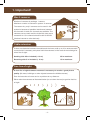
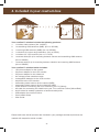
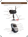
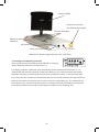
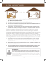
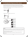
EN – User Guide
Contents
1.
Important......................................................................................................3
2.
Introduction..................................................................................................4
3.
Safety precautions / Important information.................................................5
4.
Included in your cowCam-box.....................................................................6
5.
Explanation of the included products..........................................................7
6.
How cowCam works....................................................................................9
7.
Before you begin the installation................................................................10
8.
Setting up the camera in your barn............................................................10
9.
Installing the transmitting A300-antenna...................................................11
10. Installing the receiving A300-antenna........................................................12
11. Setting up the videoLink............................................................................13
12. Permanent attachment and shrink tube heating........................................13
13. The different ways to view..........................................................................14
14. Troubleshooting..........................................................................................15
15. Interference................................................................................................17
16. Changing the frequency of the camera......................................................18
17. Frequently Asked Questions (FAQ)............................................................19
18. Warranty.....................................................................................................20
19. Information regarding recycling..................................................................20
20. Technical specifications.............................................................................21
21. Contact us, accessories & support............................................................22
22. Declaration of Conformity..........................................................................23
-2-
1. Important!
Max 2 cameras
Number of cameras in package: 1 camera
Maximum number of cameras in system: 2 cameras
The reason why only 2 cameras can be used in the
system is because of possible interference between
the channels. A total of 4 channels are available. The
cameras use one each and the videoLink uses one to
retransmit on. One channel should be left for WLAN
(wireless internet or other devices).
CH4
CH3
Cable extension
If there are obstacles between the stable and the home, add up to 10 m antenna cable
on each side if necessary and place both the antennas on the roofs of the buildings for
a free line of sight.
Sending side: 25 m included (+ 10 m): 35 m maximum
Receiving side: 5 m included (+ 10 m): 15 m maximum
Free line of sight
A clear line of sight between antennas is necessary to receive a good picture
quality. (No trees, buildings or other objects between the A300 antennas)
Even the branches of a tree can be a problem at any distance.
Either raise the antennas as illustrated below (or cut down the tree) to get the free line
of sight.
-3-
2. Introduction
Congratulations to your purchase of cowCam™ from LUDA Elektronik AB.
The cowCam™-solution provides safe supervision your cattle and barn.
We hope that the cowCam™-solution will satisfy your needs and exceed your
expectations.
Note that cowCam transmits on an open frequency and that the signal is not encrypted.
This means that the signal can be captured by another 2,4GHz device within the camera
range.
The product is CE-certified meaning that it fulfils all established rules and demands for
use within the EU. The CE-certification further implies that the radiation level is below the
established radiation levels stated in the R&TTE directive (1999/5/EC).
We thank you for purchasing the cowCam™-solution and we hope you’ll easily get trough
the installation process. If questions arise during the installation, please read through the
different troubleshooting chapters and the FAQ chapter. If further questions arise you are
very welcome to contact our friendly customer support.
Before you start reading about the installation of your cowCam™-solution we ask you to
read through Chapter 3: Safety precautions / Important information.
For news on our product range or accessories to your cowCam™-solution, please visit our
website: www.cowcam-europe.com
LUDA Elektronik AB
-4-
3. Safety precautions / Important information
T
R
A
N
SM
IT
T
ER
nk
Li
eo
vid
Channel 1
R
™
!
EC
EI
V
ER
!
12V
Channel 4
AV
DC
!
5V
1
4
2 3
DC
5V
Always use the correct power adaptor for each product.
The products will be damaged if they are supplied with wrong voltage!
Do not use the products in the following places:
Do not use the products in hospitals since they might interfere with sensitive equipment.
Do not use the products on-board airplanes since they might interfere with sensitive
equipment.
Do not use the products in a way that might violate the integrity of others.
-
Always follow the laws and legislations that apply in your country.
-
Do not leave plastic packaging material near children to avoid the risk of suffocation.
-
Do not place any of the included power adaptors outside or close to water.
-
Do not cover the power adaptors or place them on heat sensitive materials.
-
Do not lift the camera or the videoLink with the antennas.
-
If you use several cameras within the same area, place the cameras/antennas in a way allowing the signals to reach the receiver from different angles.
-
Do not use several cameras with the same frequency within the same area since they will interfere with each other.
LUDA Elektronik AB resigns all responsibility that might occur from abuse or
incorrect use of the products. Always follow the instructions in this User Guide or in
the included Quick Install Guide.
-5-
4. Included in your cowCam box
BARN
HOME
1.
2.
3.
6.
5.
7.
4.
Your cowCam™-solution includes the following products:
1. 1 wireless video camera. (Art. no 905T)
2. 1 transmitting A300-antenna. (9dBi). (Art. no 307A00)
3. 1 receiving A300-antenna. (9dBi). (Art. no 307A00)
4. 1 videoLink for indoor range extension. (Art. no 870VL)
5. 1 wireless 2,5” LCD-monitor. (Art. no 711LCD)
6. 1 antenna cable (25 m) for mounting between camera and transmitting A300-antenna (Art. no 325K25)
7. 1 antenna cable (5 m) for mounting between videoLink and receiving A300-antenna
(Art. no 305K05)
Your cowCam™-solution further includes:
1 12V power adaptor for the camera.
1 5V power adaptor for the LCD-monitor.
1 5V power adaptor for the videoLink.
1 low voltage power extension cable
2 rechargeable batteries for the LCD-monitor.
1 earphone to the LCD-monitor.
1 transmitting black antenna for the camera (2dBi).
1 transmitting black antenna for the videoLink (2dBi).
1 video cable for connecting the LCD-monitor to your TV (Yellow).
1 AV-cable for connecting the videoLink to your TV or cowCam Online (Yellow/Red).
4 shrink tubes for weather protection of antenna cable joints.
1 USB adapter for cowCam Online
1 Quick Install Guide.
1 User Guide.
Please make sure that all products are included in your package and that all products are
marked with respective article number.
-6-
5. Explanation of the included products
To succeed with the installation process, it is important that you get familiar with the
included products.
Antenna (2dBi)
Protective hood
Lens
Day / Night sensor
Channel selector
Microphone
IR-LEDs
Mounting foot
Power connection (12V)
Wireless video camera. (Art. no 905T)
Volume
On/Off-button
LCD-display
Channel selector
Video out for TV
Channel indicator
Power connection (5V)
Speaker
Bracket
Wireless 2,5” LCD-monitor. (Art. no 711LCD)
-7-
Antenna (2dBi)
Antenna connection (for A300-antenna 9dBi)
Channel indicators
Manual channel
selectors
Dip switches*
Power connection (5V)
AV-out
videoLink for indoor range extension. (Art. no 870VL)
* Choosing and switching channels
You can set the receiving side to either Manual or Looping
mode. (Right dip switch set to either M or L.)
In Looping mode the videoLink will automatically switch between the channels (1, 2, 3,
4) set to ON with the dip switches. In Manual mode you can switch between the chosen
channels manually by pressing the manual channel selector button on the receiving side.
If you only use one camera we recommend that you set the dip switch to the right to M and
keep all channels off except for the one your camera is transmitting on. The videoLink will
be locked to your camera channel and will not change channels if somebody for example
by mistake presses the manual channel selector button on the receiving side.
-8-
6. How cowCam™ works
BARN
HOME
2
1
4
2
3
1.
The camera monitors your cattle, the signal is transmitted through the cable to the A300-antenna outside the barn.
2.
The signal is sent from barn to home via the A300-antennas.
3.
The videoLink receives the signal through the A300-antenna and retransmits it in your home for better picture quality.
4.
In your home, you can monitor your cattle comfortably, either wirelessly on the portable LCD monitor, or through a computer or TV connected to the videoLink.
Optimal picture quality is obtained when there is a clear line of sight, i.e. no obstacles
whatsoever between the antennas. Keep this in mind when planning your installation.
It is important that both A300-antennas are placed on the outside of the barn and the house
to reduce the number of obstacles. The antenna can be placed on the roof, outside an
upper floor or on another wall to avoid buildings or large trees in the line between the A300antennas. The included antenna cable allows the camera to be placed up to 25 m from the
transmitting A300-antenna. Extension cables are available, please contact your local retailer.
1.
Decide where you intend to place the transmitting A300-antenna and the receiving A300-antenna. It is important that the antennas are pointed as straight as possible towards each other.
2.
Make sure that there are as few obstacles (trees, bushes, buildings) as possible in the line between the A300-antennas.
3.
The receiving A300-antenna is connected to the videoLink to obtain a wireless range extension inside your house. The videoLink has a range of 20-30 meters indoors.
Information
The 2,4 GHz frequency signals are sent out as radio waves in the air. The
waves can penetrate most objects or bounce around them. However, the
signals loose strength at every obstacle (trees, windows, walls etc.) they
need to penetrate. If penetrating metal or concrete, the signal strength will
be substantially reduced.
-9-
7. Before you begin the installation
Read the whole user guide before you start installing your cowCam-solution.
Begin with charging your LCD-monitor. You will need to use it
later on in the installation process. The battery is only partially
charged at delivery. The LCD-monitor will only function for a
short while if not charged. A fully charged battery will last
for approximately 2 hours.
1. Insert one of the included batteries into the
LCD-monitor.
!
1
4
2 3
DC
2. Connect the power adaptor marked with 5V to the LCD monitor’s power socket (marked with DC 5V IN) and the other end to a wall socket (220V).
3. Make sure that the ring around the button on the LCD-
monitor lights up. The light will turn off when the battery is fully charged.
5V
NOTE!
Only use the 5V adapter marked LCD Monitor to power the monitor! Use of any other
power source may damage the receiver and is NOT covered by the warranty.
8. Setting up the camera in your barn
1. Connect the small camera antenna to the back of the camera.
2. Attach the camera to the wall, up to 12 m* from a 220V socket and up to 25 m* from where you intend to place the transmitting A300-antenna.
3. Use the LCD-monitor to check the camera angle.
*Low voltage power extension cables and longer antenna
cables can be purchased from your local retailer.
!
12V
- 10 -
9. Installing the transmitting A300-antenna
In order to send the picture from the camera wirelessly at the longest possible range, the
A300-antennas must be placed on the outer walls of the buildings, pointing directly at
each other.
1. Unplug the camera power supply.
2. Remove the small camera antenna.
3. 90˚
90˚
Attach the antenna cable to the camera and drag the cable to the outer wall where you have chosen to place the transmitting A300-antenna.
4. Attach the antenna to the wall temporarily using only 1 or 2 screws.
5. Slide the shrink tube onto the antenna cable, connect the antenna cable to the A300-antenna. Do not heat the shrink tube yet!
Information
Place the antenna as illustrated above to obtain optimal picture quality.
Make sure there are no other objects such as a roof gutter or a pipe close
to the antenna, as it may decrease the image quality.
Test the signal reception
a
As the receiving A300-antenna is
significantly more sensitive than the
built-in receiving antenna of the LCDmonitor, a somewhat unstable picture is
acceptable at this point.
c
b
c1
c2
1.
!
2.
Do this after you have made sure that you
receive interference free picture quality inside your house.
c3
- 11 -
Plug in the power to the camera again.
Test the signal reception by bringing your LCD-monitor to the place where you intend to put the receiving A300-antenna. Generally you achieve a better signal quality when placing both antennas as high as possible.
10. Installing the receiving A300-antenna
Place the receiving A300-antenna on an outer wall of your home facing the barn, and
point it towards the transmitting A300-antenna. Use the 5m antenna cable to connect the
antenna to the videoLink.
Information
Place the antenna as illustrated above to obtain optimal picture quality.
Make sure there are no other objects such as a roof gutter or a pipe close
to the antenna, as it may decrease the image quality.
5m
1. Point the receiving A300-antenna as exact as possible towards the transmitting A300-antenna.
a
2.
Screw the receiving A300-antenna temporarily on to the wall you have chosen with 1 or 2 screws.
3.
Slide the shrink tube onto the antenna cable (5m) without heating it.
4.
Lead the antenna cable to the place indoors where you will put the videoLink. Be careful not to break the cable, especially when mounting in cold weather.
b
!
- 12 -
c
Do this after you have
made sure that you
receive interference
free picture quality
inside your house.
11. Setting up the videoLink
1. Connect the 5m antenna cable to the receiving part of the videoLink.
2. Attach the square videoLink antenna to the transmitting part of the videoLink.
T
A
N
SM
IT
T
ER
nk
Li
eo
vid
Channel 1
R
EC
EI
V
ER
The camera is preset to send on channel 4. Set the videoLink to receive on the same channel as the camera is sending on.
™
4.
R
3. Connect the videoLink to a power source using the 5V power adaptor.
Channel 4
5. We recommend to set the transmitting channel of the videoLink to 1. Choose the same channel on your LCD monitor.
AV
DC
!
5V
Information
The videoLink receives the weakened signal and transmits it again with
increased strength. This way you will receive a stable and interference free
picture inside your home.
12. Permanent attachment and shrink tube heating
1. Check the picture quality in your home using the LCD-
monitor.
2. When satisfied, mount the A300-antennas permanently and heat the shrink tube over the antenna connection.
- 13 -
13. The different ways to view
The standard way to view the picture from your camera is by using the LCD monitor as you
have done in the installation, but you can also view in three other ways:
Viewing online through cowCam Online (mobile phone or computer)
cowCam Online is free during the first 30 days, and you
can watch over your cattle from anywhere in the world,
using a mobile phone or computer with an internet
connection.
After the first 30 days, further subscription to the service
is entirely optional.
To get started, go to http://cowcam-online.com and
follow the instructions.
Viewing locally on a computer
Included in the cowCam is LUDA Camera Viewer, an easy
to use software for viewing your camera on your PC without
connecting to the internet.
Insert the CD included in the cowCam box into your
computer, open Instructions.pdf on the CD and follow the
instructions.
Viewing on a TV
1. Connect the AV-cable to the videoLink and then to your TV.
(Red to red, yellow to yellow, in the same way as you would
connect for example a DVD player.)
2. Choose the AV-In/Video Channel on your TV.
- 14 -
14. Troubleshooting
In this Troubleshooting chapter we will presume that you have mounted and installed all
parts of your cowCam system.
Troubleshooting is also available online at http://ludaelektronik.com/support/en/
Please see chapter 21 for contact information to our support team.
1.
–
–
–
–
–
–
–
We will start troubleshooting using the portable LCD monitor.
If you can’t see a picture on any of the channels, and the monitor is completely black, go to section 2.
If the picture is black on one or more channels, but not all, go to section 3.
If there is only noise on all channels, go to section 4.
If there is interference in the picture, read chapter 15, Interference.
If you see a bright circle in the picture, read chapter 15, Interference.
If the picture is black and white/lacking in colour, read chapter 15, Interference.
If the contrast is very sharp, read chapter 15, Interference.
2.Make sure that the monitor is connected to a power source and is turned on. One of the channel indicators should light up, and when charging the red ring
around the channel button should be lit up as well. If no LEDs are lit please
check the following:
– That the battery is charged. Charge by using the included 5V adapter or change battery. If the b
attery seems to have very short battery life, you may need to get a new one.
– If you experience problems with charging the monitor or if the display is black despite the LCD monitor is receiving power, please contact customer service.
Never charge the monitor with any other adapter than the included 5V adapters! Charging with the wrong adapter may lead to damage on the equipment not covered by the warranty.
3.
–
A black picture on one of the channels, but not all, is caused by a transmitting unit sending a b
lack picture. Is it the camera or the videoLink that is sending a black picture?
If the camera is sending black it is likely that you see a black picture both on the channel the camera is transmitting on and the one transmitted by the videoLink. Check the camera picture by standing close to the camera antenna, choose the channel the camera is sending on. Turn the videoLink off before doing this, to avoid mistaking one channel for the other. Please contact the LUDA support after checking this.
4.
Check if the camera is supplied with power by cupping your hands around and peeking into the camera lens. The IR light should turn on, and you should see a red light.
- 15 -
–
–
If you see a red light the camera is supplied with power, proceed to step 5.
If not please check that the adapter is connected to a working socket, connected to the camera, marked 12V and that the cable isn’t damaged in any way.
5. Make sure that the camera is working by screwing the small black antenna back on and holding the LCD monitor nearby.
– If you do not receive a picture using the small antenna, contact the support.
– If you do receive a picture using the small antenna, please screw the A300 antenna
cable back on and check that the antennas are mounted with the “spikes” horisontally, that the cable isn’t damaged and that the cables are connected properly.
– If you can’t find any problem with the antennas, go to section 6.
6.
Begin with making sure the channel switchers are set correctly. The switch to the right
marked with M L sets the videoLink to Automatic Channel Looping (L) or Manual Channel (M). The important switches for the troubleshooting are the four other switches. By setting them to o
n or off, you choose which channels the videoLink is to
receive on, in other words the channel(s)l your camera(s) is sending on. For example, if the camera is sending on channel 4, the switch marked 4 should be set to ON. (Pointing down)
On the top side of the videoLink, on the right side (Receiver) you will see the receiving channels you have chosen. If we follow the example above we will see number 4 lit up.
On the left side (Transmitter) you will see the channel the videoLink is retransmitting the camera signal on. The transmitting channel must not be the same as the receiving channel. In our example it would be suitable to let the videoLink transmit on channel 1 or 2.
–
–
–
When troubleshooting the videoLink, choose the transmitting channel of the videoLink on the LCD monitor.
If you only see noise in the LCD monitor and no LEDs on the videoLink are lit up, please check that the adapter is connected to a working socket, connected to the videoLink, marked 5V and that the cable isn’t damaged in any way.
If the LEDs on the videoLink are lit up, but you only see noise in the LCD monitor, check that the channels are set correctly.
If you see interference in the picture, please go to chapter 15, Interference.
- 16 -
15. Interference
Interference caused by WLAN, microwave ovens and wireless telephones.
Other wireless equipment around the camera or receiver may cause interference in the
picture. WLAN, microwave ovens and wireless telephones may cause horizontal lines
across the display and a clicking sound. Microwave ovens only cause interference when in
use.
This can be resolved by changing the frequency of the WLAN or the camera, as described
in the next chapter.
Interference caused by one or more units are sending on the same channel
Make sure that the cameras are sending on separate channels. Also make sure that the
videoLink isn’t sending on a channel that a camera is already sending on, and not receiving
on the channel the videoLink is sending on.
Very high contrast
A picture where the contrast is very high is often caused by metal objects, for example
drainpipes, within one meter of the antenna. Move the interfering objects or the antenna.
videoLink interference
If you are using the videoLink and experiencing interference that goes away when you
place your hand on the videoLink or remove the sending antenna, please contact our
support for further assistance.
There is a bright circle in the middle of the picture
The IR bulbs that makes it possible to monitor in the dark are placed in a ring around the
lens of the camera. Hence the light can be experienced as ring shaped, but this is normal.
Try to move the camera further away from the box and make sure it isn’t placed behind
glass, as the light will bounce back into the lens.
You can increase the IR light by purchasing our Extra Night Light accessory.
The picture is black and white/there is almost no colour in the picture
In dark surroundings the IR light is turned on. The darker the room, the more black and
white the picture will be, as the camera goes from filming daylight with many colours, to IR
light with only one colour. If the picture seems to be black and white even though the room
is well lit, try moving the camera into strong daylight. If the picture is in colour when doing
this, the camera is OK. Sometimes a room seems more lit up to the naked eye than it really
is.
- 17 -
16. Changing the frequency of the camera
If you believe that interferences in the picture are not a result of unnecessary obstacles
between the antennas, we advise you to change the camera frequency. The cowCam
camera can be changed to any of the four radio frequencies to avoid possible interferences.
Please take a look at the illustrations to learn how the respective frequency can be set.
1. Slide the camera hood forward
2. Rotate the camera objective counter clock-wise.
3. Change the dip switches according to the illustration.
1
2
Channel 1
2414MHz
1
2
Channel 2
2432MHz
12
1
2
Channel 3
2450MHz
1
2
Channel 4
2468MHz
NOTE!
By changing the camera frequency you change the transmitting channel of the camera.
If you do this you also need to change the channel of the receiving part of the videoLink.
The transmitting channel of the camera and the channel of the receiving part of the
videoLink should always be the same.
Also make sure that the videoLink is transmitting on a different channel than it is
receiving on.
- 18 -
17. Frequently Asked Questions (FAQ)
1.
Is the signal between the camera and the receiver encrypted?
The signal between the camera and the receiver is not encrypted and is not possible to encrypt. In order to catch the signal, a receiver must be within range and on the same frequency as the camera.
2.
What does a clear line of sight mean?
A clear line of sight means that no objects what so ever (walls, trees etc.) are
inbetween the camera and the receiver. The picture will gradually worsen and become more and more unstable when the camera gets too far away from the receiver.
3.
Is the camera water resistant?
The camera in your cowCam™-solution is IP66 classed. This means that the camera is well protected from both dust and humidity. It can be put outside in rain or in damp environments such as barns.
4.
Is it possible to add extra cameras to my cowCam™ solution?
It is possible to add cameras to your cowCam™-solution. Please contact your retailer or visit http://cowcam-europe.com
5.
Can I see my cattle on my TV/computer/mobile phone?
Yes! More information is available in Chapter 13: The different ways to view
6.
How do I obtain a wider camera viewing angle?
The camera covers up to 60-80 m2 depending on placement. Try to move the camera or extend your system to include more than one camera to supervise a larger area. For the latest product news visit: www.cowcam-europe.com
7.
Will the camera break at very low temperatures?
No, at very low temperatures the picture might tone into red. At extremely low temperatures the camera might turn off. However, when the temperature goes up again the camera will regain its functionality.
8.Further questions?
You are always welcome to visit our website www.ludaelektronik.com or contact us directly (see chapter 21. Contact us).
- 19 -
18. Warranty
The warranty is due, if no other terms agreed, 12 months from the date the product is
purchased from the authorised LUDA Elektronik AB dealer. During the warranty time
LUDA Elektronik AB is obliged to repair, alternately, replace the broken product to a
similar product or a product with better functions. When LUDA Elektronik AB replaces the
product, the new product will be covered by the original warranty during the remaining
warranty time. If your product is replaced, previously used, completely functioning parts
might be used. Replaced parts are owned and controlled by LUDA Elektronik AB.
The warranty does not cover damage that have arisen due to physical damage, accidents,
natural disasters, the usage of incorrect power adaptors or usage of the products in
deviant behaviours from what is recommended by LUDA Elektronik AB and in this users
guide.
The end consumer will be responsible for all shipping costs that occur from transportation
to the LUDA Elektronik AB repair shop. The warranty will only be valid if the original receipt,
issued by the authorised LUDA dealer, can be presented. The original receipt needs to
contain information regarding place of purchase, issue date and product description.
LUDA Elektronik AB reserve the right to refuse to perform the warranty service if above
mentioned receipt information has been removed, changed or is missing.
19. Information regarding recycling
The crossed-out wheeled-bin symbol on your product, battery, literature, or packaging
reminds you that all electrical and electronic products, batteries, and accumulators must
be taken to separate collection at the end of their working life. This requirement applies in
the European Union. Do not dispose of these products as unsorted municipal waste.
Always return your used electronic products, batteries, and packaging materials to a
dedicated collection point. This way you help prevent uncontrolled waste disposal and
promote the recycling of materials. Batteries can contain mercury, lead or cadmium substances that are harmful to our health and our environment. More detailed information
is available from the product retailer, local waste authorities or your national producer
responsibility organization.
- 20 -
20. Technical specifications
Wireless video camera (Art. no 905T)
Transmitting frequency
Transmission power
Channels
Transmitting antenna
Imaging sensor
Resolution
Horizontal resolution
Angle
Minimum Illumination IR night range Power supply
Power consumption
Operating temperature Size (W×D×H)
Weight ISM 2400~2483 MHz < 10mW/CE
2414MHz (CH1); 2432MHz (CH2); 2450MHz (CH3); 2468MHz (CH4)
50 ohm SMA
CCD PAL: 512×582
420TV Lines
PAL: 90°
0Lux 10m DC +12V 120mA (IR OFF) & 270mA (IR ON) -20 ~ +50 (Celsius)
50*50*75 mm 200g
Wireless 2,5” LCD-monitor (Art. no 711LCD)
LCD screen type
TFT
Display size
2,5”
Resolution
480x234
Contrast
150:1
Channels
2414MHz (CH1); 2432MHz (CH2); 2450MHz (CH3); 2468MHz (CH4)
Receiver sensitivity
< -85dBm
Video out
1V p-p @ 75 ohm
Audio out
1V p-p @ 600 ohm
Power supply
DC +5V Power consumption
700mA
Operating temperature
±0 ~ +45 (Celsius)
Size (WxDxH)
80*38*130 mm
Weight
250g
videoLink (Art. no 870VL)
Transmitting frequency
Transmission power
Channels
Transmitting antenna
Receiving sensitivity
Video out
Audio out
Power supply
Power consumption
Operating temperature
Size (BxDxH)
Weight
ISM 2400~2483 MHz 10mW/CE
2414MHz (CH1); 2432MHz (CH2); 2450MHz (CH3); 2468MHz (CH4) 50 ohm SMA
< -85dBm
1V p-p @ 75 ohm
3V p-p @ 600 ohm
DC +5V 180mA
-10 ~ +50 (Celsius)
68*16*156 mm
240g
- 21 -
21. Contact us, accessories and support
LUDA Elektronik, founded in 2003, is a leading distributor of wireless video equipment. We
have in-depth expertise of wireless video technology and its usage areas. Thanks to this
we can offer our customers the latest products and high quality sales support, service and
customer support.
Accessories and support
Visit www.ludaelektronik.com/support/en/ for support and accessories for your cowCam.
Contact:
LUDA Elektronik AB, Aschebergsgatan 46, SE41133 Göteborg, Sweden
Tel: +46 (0)31 3130290
Fax: +46 (0)31 3130299
E-mail: [email protected]
- 22 -
22. Declaration of conformity
R&TTE Declaration of Conformity (DoC)
R&TTE Declaration of Conformity (DoC)
Unique identification of this DoC: 621COW-2010-2-CE
We, LUDA Elektronik AB,
Unik identifiering av denna DoC: 621COW-2010-2-CE
Vi, LUDA Elektronik AB,
declare that the product:
product name: cowCam
type or model: 621COW
to which this declaration relates is in conformity with the
essential requirements and other relevant requirements of
the R&TTE Directive (1999/5/EC). The product is in
conformity with the following standards and/or other
normative documents:
försäkrar att:
produktnamn: cowCam
typ eller model: 621COW
överensstämmer med gällande direktiv och standarder
samt uppfyller kraven enligt R&TTE Directive
(1999/5/EC):
Aschebergsgatan 46
411 33 Göteborg
Sweden
Phone: +46 31 3131290
Aschebergsgatan 46
411 33 Göteborg
Sweden
Phone: +46 31 3131290
HEALTH & SAFETY (Art. 3(1)(a)):
EN 50371:2002
EN 60950-1:2006 + A11:2009
HEALTH & SAFETY (Art. 3(1)(a)):
EN 50371:2002
EN 60950-1:2006 + A11:2009
EMC (Art. 3(1)(b)): Electromagnetic Compatibility (EMC)
Directive 2004/108/EC
EN 301 489-1 V 1.8.1
EN 301 489-3 V 1.4.1
EMC (Art. 3(1)(b)): Electromagnetic Compatibility (EMC)
Directive 2004/108/EC
EN 301 489-1 V 1.8.1
EN 301 489-3 V 1.4.1
SPECTRUM (Art. 3(2)):
EN 300 440-1 V1.5.1
EN 300 440-2 V1.3.1
SPECTRUM (Art. 3(2)):
EN 300 440-1 V1.5.1
EN 300 440-2 V1.3.1
Technical file held by:
LUDA Elektronik AB
Aschebergsgatan 46
411 33 Göteborg
Sweden
Teknisk dokumentation finns hos:
LUDA Elektronik AB
Aschebergsgatan 46
411 33 Göteborg
Sweden
Place and date of issue (of this DoC):
Göteborg, 2010-06-17
Ort och datum (för denna DoC):
Göteborg, 2010-06-17
Signed by or for the manufacturer:
Signatur för tillverkaren:
.................................................................................
Name (in print): Ludvig Brost
Title: CEO
.................................................................................
Namn (textat): Ludvig Brost
Titel: VD
Signed by or for the manufacturer:
Signatur för tillverkaren:
.................................................................................
Name (in print): Daniel Ludwiszewski
Title: Product Manager
.................................................................................
Namn (textat): Daniel Ludwiszewski
Titel: Produktansvarig
- 23 -
© Copyright LUDA Elektronik AB 2011
This guide is published by LUDA Elektronik AB.
All rights reserved. Any rights not expressly granted herein are reserved.
- 24 -