1
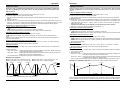
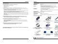
General Contents General Operating instructions I / 2007 Installation Operation Appendix Safety information Definition of terms Application and function Components Wiring diagrams Wiring diagrams System extension Master/slave mode Remote control display Remote control settings Lighting control mode Sequencer mode Daylight simulation Troubleshooting Technical data 2 3 4 5 6 7 8 9 10 11 12 13 14 15 16 Safety information DALI EASY II Version 1.0 The following information is provided for your safety: OSRAM GmbH Customer-Service-Center (CSC) Steinerne Furt 6286167 Augsburg, Germany Tel. : (+49) 1803 / 677 - 200 (charges apply) Fax.: (+49) 1803 / 677 - 202 www.osram.com www.osram.de • Please read these operating instructions carefully before installing and using the DALI EASY lighting controller. This is the only way to ensure that you use the equipment safely and correctly. Keep these operating instructions in a safe place for future reference. You should make sure that everyone who uses DALI EASY has read these operating instructions. • DALI EASY is intended exclusively for operating control gear with a DALI interface. No further control units may be operated on the control line. The appropriate infra-red receiver must be used (see Technical data). • DALI EASY may only be installed by qualified personnel who have been appropriately trained and who have the relevant authority. The installation personnel must be familiar with the operating instructions. Power must be switched off before any work is undertaken on the unit. • The EASY control unit is especially designed for installation within luminaires, an independent installation is only allowed in combination with the mounting kit LMS CI BOX. • The relevant safety and accident prevention regulations must be observed. • The external switch must be designed for mains voltages. • If the control cable or switch input is wired with external voltage, particularly with a mains voltage of 230 V, the unit may be destroyed. Page 2 OSRAM- Operating Instructions: DALI EASY II control unit General General Definition of terms Application and function Sequence The DALI EASY lighting control unit has four channels. With the remote control 4, with the push button coupler 12 and via PC up to 16 lighting scenes can be stored and retrieved. Most settings are made from an infra-red remote control. An external (light) switch can also be used to switch all the luminaires on and off and to fade them up and down. A sequence is taken to be the automatic retrieval of stored lighting scenes and their cyclic playback. Group, luminaire group A group is a collection of luminaires connected to the same DALI output channel. This means that all the luminaires in a group always have the same brightness. IR receiver The infra-red receiver receives the signals from the remote control and forwards them to the DALI EASY controller. Short press With DALI EASY it is possible to set up a coloured light mixing system in which a different lamp colour (red, green, blue and white) is assigned to each group. By setting the individual groups to different values, any colours can be “mixed”. These colours can be stored as lighting scenes and retrieved at any time. A uniform distribution of the light colour can be achieved by arranging the coloured luminaires behind diffusors. DALI EASY can be synchronised with other DALI EASY light controllers via a master-slave connection. This means that more than 32 DALI units can be provided per installation. A short press means pressing a pushbutton for less than one second. A short press is used for example for switching luminaires on and off. DALI EASY has three operating modes: Long press A long press means pressing a pushbutton for more than one second. A long press is used for example for dimming the luminaires. The lighting levels and the lighting scenes are adjusted manually. In lighting control mode with the remote control up to four, with the push button coupler up to 12 static lighting scenes can be stored and retrieved. Light switch Sequencer mode Light switches are used to switch luminaires on and off in a room and to fade them up and down. They are connected to the “external switch” input on the DALI EASY controller. In sequencer mode the lighting scenes stored by the user are called up automatically one after the other. The fade time between the individual lighting scenes can be adjusted. If DALI EASY is used as a colour mixing system, automatic colour changes are generated. Scene, lighting scene A lighting scene defines the lighting situation in a room. This presupposes that there are a number of luminaires or luminaire groups in a room and that their brightness can be adjusted independently of one another. Example 1: Office lighting Offices often have rows of luminaires running in parallel to the window. Lighting scene A: (in daylight) The luminaires near the window are set to minimal brightness. The luminaires furthest away from the window are set to maximum brightness. Lighting scene B: (after dusk) All the luminaires are set to the same brightness. Lighting control mode Daylight simulation Daylight simulation operates in much the same way as the sequencer mode. The difference is in the use of lighting scenes that correspond to the lighting conditions as they change during the course of a day. The duration of the entire cycle (in other words a simulated day) and the predefined lighting scenes can be changed. DALI EASY is not intended for any applications other than the ones indicated here. Other applications are considered to be inappropriate. If DALI EASY is used inappropriately there is no guarantee that it will operate safely. Example 2: Coloured effect lighting Behaviour after a power failure The luminaires or luminaire groups have different colours (red, green, blue, white). They are set to different brightness levels according to the shade of colour required for the room lighting. This mixing colour is a lighting scene. In the event of a power failure the luminaires behave as follows: Fade time • The fade time is the time in which the lighting system changes from one lighting scene to the next in sequencer mode. Sequencer mode Cycle time Lighting control mode • The last status before the power failure is automatically restored. The sequence is restarted, beginning with the first active scene. Daylight simulation The cycle time is the time in which the daylight simulation system runs through a complete daylight cycle. • OSRAM – Operating Instructions: DALI EASY II control unit Page 4 Page 3 The simulation is restarted, beginning with the first active scene. OSRAM- Operating Instructions: DALI EASY II control unit General Installation Components Wiring diagrams DALI EASY II control unit: Controlling fluorescent and low voltage halogen lamps N PE L Line switch or clock controlled switch (optional) external push button (optional) L N Easy Signal GND (-) CH4+ (W) CH3+ (B) CH2+ (G) CH1+ (R) DALI ECG lamp (red) Remote control type EASY RMC (accessories, not included) Y-Connector OSRAM Infra-red transmitter ON DIP Display Channel switches: Ch1 Ch2 Ch3 Ch4 Start / Time+ Stop / Time - Infra-red receiver (optional) DALI ECG lamp (green) DALI ECG 4 lamp (blue) Scene 1 Scene 2 Scene 3 Scene 4 Y-Connector ~ ~ DALI transformer Halogen lamps Y-Connector max. 100m overall cable length 1 2 3 4 DALI ECG lamp (white) On/Off Dimming DIP-Switches Push button coupler (optional) EASY PC Kit (optional) Note: Make sure that there is a line of sight between the IR receiver and the remote control. Up to 4 IR receivers may be connected. To ensure that the remote control function operates properly, the IR receiver must not be exposed to direct light. Wherever possible, mount the IR receiver in a shaded spot. OSRAM – Operating Instructions: DALI EASY II control unit Page 5 Page 6 OSRAM- Operating Instructions: DALI EASY II control unit Installation Wiring diagrams Installation System extension Master/slave circuit Controlling LED modules N N L L Line switch and/or clock controlled switch Line switch and / or clock controlled switch (optional) PE external push button (optional) L N external push button (optional) OT Supply 24V L N L N Easy Signal GND (-) CH4+ (W) CH3+ (B) CH2+ (G) CH1+ (R) DALI ECG lamp (red) + R G B Infra-red receiver (optional) LED moduls LINEARlight Colormix Infra-red receiver (optional) Y-Connector Easy Signal OTi DALI OTi DALI GND (-) CH4+ (W) CH3+ (B) CH2+ (G) CH1+ (R) DALI ECG Y-Connector lamp (green) OTi DALI 4 DALI ECG lamp (blue) Y-Connector Push button coupler (optional) DALI ECG lamp (white) L N Y-Connector max. 100m overall cable length EASY PC Kit (optional) GND (-) CH4+ (W) CH3+ (B) CH2+ (G) CH1+ (R) Easy Signal DALI ECG lamp (red) Y-Connector up to 15 Slaves DALI ECG Note: lamp (green) 4 Make sure that there is a line of sight between the IR receiver and the remote control. Up to 4 IR receivers may be connected. To ensure that the remote control function operates properly, the IR receiver must not be exposed to direct light. Wherever possible, mount the IR receiver in a shaded spot. Y-Connector Push button coupler (optional) DALI ECG lamp (blue) DALI ECG lamp (white) Y-Connector max. 100m overall cable length EASY PC Kit (optional) Note: In the master/slave circuit there must be precisely one master; all other control units must be configured as slaves by having a bridge placed over the switch input. OSRAM – Operating Instructions: DALI EASY II control unit Page 7 Page 8 OSRAM- Operating Instructions: DALI EASY II control unit Installation Master/slave mode Operation Remote control display In master/slave mode, up to 16 DALI EASY or OT EASY lighting controllers can be controlled simultaneously via a single remote control, a single push button coupler or a single PC. This means that lighting systems with more than 32 DALI units can easily be set up. Display in response to buttons Display This is how to set up the master/slave circuit (see wiring diagrams): 1. For one lighting controller you should proceed as follows: If required, connect an external switch or leave the switch input free. This lighting controller will act as the master. 2. For all the other lighting controllers, bridge the input of the external switch. These lighting controllers will be automatically recognised as slaves when mains voltage is applied. 3. Connect the individual DALI EASY lighting controllers using the connecting cable provided. Use “YConnector” (available as an accessory) for branching. 4. Connect the infra-red receiver to one of the “Y-Connector” units. b) 1. 2. 3. 4. 5. 6. 7. 8. 9. Configuration via remote control: Remove the bridges from the external switch inputs on all the lighting controllers. Connect the infra-red receiver to the DALI EASY lighting controller to be set. Set up the lighting scenes you require and store them. Repeat steps 2 and 3 for all the other DALI EASY lighting controllers. For one lighting controller you should proceed as follows: If required, connect an external switch or leave the switch input free. This lighting controller will act as the master. For all the other lighting controllers, bridge the input of the external switch. These lighting controllers will be automatically recognised as slaves when mains voltage is applied. Connect the individual DALI EASY lighting controllers using the connecting cable provided. Use “YConnector” (available as an accessory) for branching. Connect the infra-red receiver to one of the “Y-Connector” units. Activate the scene lock so that the lighting scenes already set are not changed by mistake. To do this, set DIP switch 2 on the remote control to OFF. Description The sequence or daylight simulation is started hold The sequence or daylight simulation is put on hold scene 1…4 Scenes 1 to 4 are called up daylight Scenes 1 to 4 of the daylight simulation are called up scene 1...4 daylight Daylight simulation is started sequence learn IRA new IR coding is transferred sequence A command via “Ch1..4” or “On/Off/Dimming” is transferred The function is not available in the current operating mode. The special case of expert mode: different sequences for master and slaves For each DALI EASY controller, sequences with different lighting scenes can be set as described below. The master determines the fade time and ensures that the individual sequences run in synchronism. a) Configuration via PC (please see EASY Color Control Software manual) Meaning sequence Display for the fade time of a sequence Description Effect Light Display Time range 0.1 to 0.9 seconds Wellness 1 to 59 seconds Long Time 1 to 99 minutes Display for the cycle time in daylight simulation Description Daylight simulation Display Time range 1 to 24 hours Notes on master/slave mode In the master/slave circuit there must be precisely one master; all other control units must be configured as slaves by having a bridge placed over the switch input. Up to 4 IR receivers may be connected. In expert mode, to delete control units that have already been programmed and to return to normal master/slave mode you need to perform a RESET as described on page 11. OSRAM – Operating Instructions: DALI EASY II control unit Page 9 Page 10 OSRAM- Operating Instructions: DALI EASY II control unit Operation Operation Remote control settings Lighting control mode The following settings can be made using the DIP switches in the battery compartment of the remote control: If a sequence or a daylight simulation is terminated the system changes to lighting control mode automatically. DIP switch 1 OFF 1 ON 2 OFF 2 ON 3 OFF 3 ON 4 OFF 4 ON 3 / 4 ON / ON Switching on a luminaire group: Function IR code 1 is active IR code 2 is active Storing of scenes is disabled Storing of scenes is enabled Sequencer mode is disabled Sequencer mode is enabled Daylight simulation is disabled Daylight simulation is enabled Learn mode for transferring the IR code to DALI EASY and resetting DALI EASY to the factory defaults (RESET) Disabling scene storage Storing of scenes can be disabled by means of DIP switch 2. The ensures that scenes cannot be changed by mistake. The DIP switch positions are shown in the table. Switching off a luminaire group: Briefly press the button for the luminaire group (“Ch1” to “Ch4”) that you want to switch off. The luminaires in the selected group are switched off. Switching on all the luminaires: Briefly press the “On/Off; Dimming” button or the external switch (light switch). Short press: All the luminaires are switched on. Long press: All the luminaires are switched on and faded from minimum to maximum brightness. Switching off all the luminaires: Changing between sequencer mode and daylight simulation Sequencer mode and daylight simulation mode are activated using DIP switches 3 and 4. Both operating modes may also be deactivated. DALI EASY then operates in lighting control mode. The necessary DIP switch positions are shown in the table. RESET or setting the IR code The two IR codes enable two separate DALI EASY lighting control systems to be operated in the same room, each with its own remote control with no interference between them. This is how you process a RESET and change the infra-red codes: 1. Set the infra-red code you want on DIP switch 1: • DIP switch 1 to OFF:IR code 1 • DIP switch 1 to ON: IR code 2 2. Note the settings of DIP switches 3 and 4. 3. Set DIP switches 3 and 4 to ON. 4. Press any button on the remote control (the remote control must be pointing at the IR sensor). ” then appears on the remote control display. The luminaires provide confirmation of the “ setting: • For IR code 1: the luminaires flash once • For IR code 2: the luminaires flash twice 5. Set DIP switches 3 and 4 to their original positions. The functions of the DIP switches are given in the table above. Notes on RESET and changing the IR code: In the event of a RESET or change of IR code, all the connected control units are reset or changed. You should therefore disable the connection to the IR receiver for the control units that are not to be reset or changed, or disconnect the power supply for these units. If there is more than one system in the reception area their IR receivers must first be disconnected or adequately covered to avoid an unwanted RESET. OSRAM – Operating Instructions: DALI EASY II control unit Press the button for the luminaire group (“Ch1” to “Ch4”) that you want to switch on. Short press: The luminaires in the selected group are switched on. Long press: The luminaires in the selected group are switched on and faded from minimum to maximum brightness. Page 11 Briefly press the “On/Off; Dimming” button or the external switch (light switch). All the luminaires are switched off. Fading luminaires in a group: Press the button for the luminaire group (“Ch1” to “Ch4”) that you want to fade up or down. Hold down the external switch until the required brightness is reached. The longer you hold it down the more the brightness will change. Fading all the luminaires: Press the “On/Off; Dimming” button or the external switch (light switch). Hold down the switch until the required brightness is reached. The longer you hold it down the more the brightness will change. Changing the fade direction: 1. The fading operation will stop when you release the button or switch. 2. Press the button or switch again. The fade direction is reversed. Storing lighting scenes: 1. Set the lighting scene you want using buttons “Ch1” to “Ch4”. 2. Press the button for the scene you want to store. Hold down the button. After about three seconds the luminaires will flash to indicate that the scene has been successfully stored. 3. Release the button. Calling up a scene: Briefly press the button for the scene (“Scene 1” to “Scene 4”) that you want to call up. The selected scene ( Page 12 ) appears on the display. The scene is called up OSRAM- Operating Instructions: DALI EASY II control unit Operation Operation Sequencer mode Daylight simulation Sequencer mode is enabled bringing DIP-Switch 3 in the remote control battery compartment into ‘ON’ and DIP-Switch 4 into ‘OFF’ position. Further DIP-Switch positions are given in the table on page 11. Daylight simulation mode is enabled bringing DIP-Switch 4 in the remote control battery compartment into ‘ON’ and DIP-Switch 3 into ‘OFF’ position. Further DIP-Switch positions are given in the table on page 11. Creating a sequence 1. Set the first lighting scene of the sequence using buttons “Ch1” to “Ch4”. 2. Press the “Scene 1” button. Hold down the button. After about three seconds the luminaires will flash to indicate that the scene has been successfully stored. 3. Release the button. 4. Repeat steps 1 to 3 to store the subsequent lighting scenes in the sequence with buttons “Scene 2” to “Scene 4”. The sequence created in this way always starts with scene 1, runs through scenes 2 to 4 and starts again with scene 1. Lighting scenes for which all the channels are switched off are skipped. Switching on a sequence and continuing a sequence: Briefly press the “Start; time +” button. Switching on and continuing a sequence: “ ” appears on the display. The sequence is started or continued. An interrupted sequence is also continued after a short press onto the external switch. 1. Briefly press the “Start; time +” button. ” appears on the display. The sequence is started or continued. “ An interrupted simulation sequence is also continued after a short press onto the external switch. Interrupting a sequence (placing on hold): Press the external switch or briefly press the “Stop; time +” button . Interrupting a sequence (placing on hold): Ending a sequence and change to light control mode: End the sequence by pressing any of the “Ch1” to “Ch4”, “Scene 1” to “Scene 4” or “On/Off; Dimming” buttons. The function of the button pressed will be performed. Setting the fade time: 1. Press the “Start; time +” or “Stop; time –“ button for about three seconds until the current fade time is shown on the display. 2. Set the fade time: “Start; time +” button: Holding down the button increases the time at a rapid pace. Briefly pressing the button increases the time in individual steps. “Stop; time -” button: Holding down the button shortens the time at a rapid pace. Briefly pressing the button reduces the time in individual steps. The new fade time is activated when the sequence is started next time. Example of a sequence: brightness Scene 1: Ch1 (red)= max.; Ch2,Ch3,Ch4= min. Scene 2: Ch2 (green) = max; Ch1,Ch3,Ch4 = min. Scene 3: Ch3 (blue)= max.; Ch1,Ch2,Ch4= min. Scene 4: Ch1..Ch4 = off (will be skipped) Scene 2 red green blue Scene 3 1. Press the external switch or briefly press the “Stop; time +” button. “ ” appears on the display. The sequence is stopped. The sequence can be resumed with the external switch or with the “Start; time +” button, provided no other button has been pressed after the sequence was interrupted. Ending a sequence: 1. End the sequence by pressing any of the “Ch1” to “Ch4”, “Scene 1” to “Scene 4” or “On/Off; Dimming” buttons. The function of the button pressed will be performed. Setting the cycle time: 1. Press the “Start; time +” or “Stop; time –“ button for about three seconds until the current fade time is shown on the display. 2. Set the fade time: “Start; time +” button: Holding down the button increases the time at a rapid pace. Briefly pressing the button increases the time in individual steps. “Stop; time -” button: Holding down the button shortens the time at a rapid pace. Briefly pressing the button reduces the time in individual steps. The new cycle time is activated when the sequence is started next time by the remote control. Example of a simulation sequence: Cycle time 12h., clock controlled switch on at 8a.m. Scene 3 brightness ” appears on the display. The sequence is stopped. The sequence can be resumed with the “ external switch or with the “Start; time +” button, provided no other button has been pressed after the sequence was interrupted. Scene 1 Creating a daylight simulation sequence 1. Set the first lighting scene of the sequence using buttons “Ch1” to “Ch4”. 2. Press the “Scene 1” button. Hold down the button. After about three seconds the luminaires will flash to indicate that the scene has been stored. 3. Release the button. 4. Repeat steps 1 to 3 to store the subsequent lighting scenes in the sequence with buttons “Scene 2” to “Scene 4”. The sequence created in this way always starts with scene 1, runs through scenes 2 to 4 and starts again with scene 1. Lighting scenes for which all the channels are switched off are skipped and not used. The fade time between the scenes depends on the selected cycle time as follows: Fade time = cycle time / (number of lighting scenes stored – 1) Scene 2 90% 80% Scene 4 Scene 1 50% Cycle time time fade time hold time* 8a.m *The hold time is set automaticially to 25% of the fade time. OSRAM – Operating Instructions: DALI EASY II control unit 12a.m. 4p.m. 8p.m. clock time If the groups are equipped with lamps of different colour temperature, beside a change of brightness, also a dynamique change of colour temperature dependent on the time of day can be achieved. Page 13 Page 14 OSRAM- Operating Instructions: DALI EASY II control unit Appendix Appendix Technical data Troubleshooting Designation: Power supply: Inputs: The luminaires cannot be switched on. Possible causes: • There is no power. Check the fuses for the power supply. • The lamps are faulty. Replace them. The DALI EASY lighting controller is not reacting to the remote control. Possible causes: • Switch DALI EASY on at the external switch (light switch). If the luminaires do not respond to the external switch (light switch), check the lamps and the power supply. • The batteries in the remote control are too weak. Press a switch on the remote control. There must be something showing on the display. If this is not the case, change the batteries. Make sure the batteries are inserted correctly. • The remote control is outside the range of the infra-red receiver. Hold the infra-red transmitter on the remote control close to the infra-red receiver. Press a switch on the remote control. The LED on the infra-red receiver must flicker. If this is not the case, check the IR code. • The IR receiver is “blinded” by direct light. Shade the IR receiver and if possible choose a different mounting location. The DALI EASY lighting controller is not reacting to the external switch. Possible cause: • Switch DALI EASY on using the remote control. If the luminaires do not respond to the remote control, check the lamps and the fuses for the power supply. The luminaires are not doing what you want them to. Possible causes: • The switch is being pressed too long or not long enough. DALI EASY distinguishes between a long and a short press. Please check the information in these operating instructions. • The power supply has been interrupted. Read the section on what happens after a break in the power supply. DALI EASY II L, N IR-Sensor input, SELV equivalent, basic insulation to IEC 664 potential-free switch input, basic insulation Outputs - 4 DALI broadcast control signals, basic insulation to IEC 664 - max. 32 DALI devices connectable (64 mA total over all channels) - max. 100m DALI control wire (total over all channels) Master-slave - max. 100m connection cable in total connection: - max. 10 slaves connectable - do not run master-slave connections together with power cables or lamp wires Operating voltage: 100-230V AC 50/60 Hz (DC operation allowed) Power input: approx. 3,5 W Operating temperature: 0 °C …+ 50 °C Protection type: IP 20 CE requirement: EMC to EN 61547, EN 61347-11 Dimensions: 189 x 30 x 21 mm (W x H x D), hole spacing for mounting: 180 mm Accessories (Not included) EASY RMC Infra-red remote control 4008321053152 Y-CONNECTOR Branch for build-up of a master-slave installation 4050300803135 EASY IR Infra-red receiver with connection cable 4008321053138 EASY PB COUPLER connection of conventional push buttons, switches or motion detectors 4008321915597 EASY PC KIT EASY USB Adapter incl. Software for facile system configuration 4008321915559 EASY IR CI Infra-red receiver for ceiling installation 4008321915573 OT EASY 60 60W 4-ch LED control unit 4008321187796 LMS CI BOX Independent mounting of DALI EASY II 4008321083692 Sensor Mounting Kit on top mounting of EASY IR CI 4008321916662 The sequence in master/slave mode is not synchronous. Possible cause: • The slaves have already been programmed and have their own scenes. Perform a RESET and create the sequence again. If you cannot remedy the problem, please contact the customer service department of your luminaire manufacturer. The CE symbol signifies compliance with the relevant EU Directives. OSRAM – Operating Instructions: DALI EASY II control unit Page 15 Page 16 OSRAM- Operating Instructions: DALI EASY II control unit