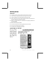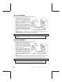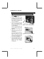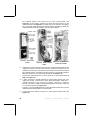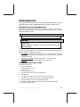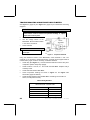
1
COLD/FROZEN SATELLITE FOOD VENDOR CF-1000/FF-2000 MODELS: 3162 - COLD FOOD 3182 - FROZEN FOOD SERVICE MANUAL SEP 2002 4211906 F TABLE OF CONTENTS INTRODUCTION ......................................... 1 SPECIFICATIONS....................................... 2 Model.................................................... 2 Food Type / Temperature Range ............... 2 Refrigeration .......................................... 2 Electrical ............................................... 2 General ................................................. 2 Pricing................................................... 2 Selections .............................................. 2 UNPACKING............................................. 3 Remove Shipping Pallet ........................... 3 INSTALLATION .......................................... 4 Checklist ............................................... 4 Locate Next To The Host ......................... 4 Grounding (Earthing) & Electrical............... 5 230 Volt Vendors .................................... 6 120 Volt Vendors .................................... 6 Connecting To The Host .......................... 7 Anchor Plate Installation .........................10 LOADING INSTRUCTIONS..........................10 Special Products....................................10 Product Ejectors ....................................10 Auger Timing.........................................11 Tray Spacing.........................................12 REFRIGERATION ......................................19 Refrigeration Troubleshooting ..................19 Compressor Will Not Start.......................19 Compressor Trips On Overload................20 Noisy Or Vibrating Unit ...........................20 Unit Short Cycles ...................................20 Unit Operates Long Or Continuously ........21 Refrigerated Space Too Cold...................21 Refrigerated Space Too Warm.................21 Troubleshooting Circuits With Multi-Meter ..22 REFRIGERATION UNIT REMOVAL (COLD FOOD ONLY) .................................23 DOOR REMOVAL ......................................25 CARE & CLEANING...................................26 Cabinet Exterior.....................................26 Cabinet Interior......................................26 Refrigeration System ..............................26 STORING THE SATELLITE FOOD VENDOR ...26 BEFORE CALLING FOR SERVICE...............27 SCHEMATIC.............................................28 REFRIGERATION CONTROL .......................13 Temperature Sensors .............................13 Host Controller Programming...................13 Default Configurations .........................13 Health Safety .....................................17 Temperature Mode ..............................17 Frozen Cycle .....................................17 Door Open .........................................18 Defrost Cycle .....................................18 Record the Model Number and Serial Number of your machine below. The Model and Serial numbers are needed to obtain quick service and parts information for your machine. The numbers are available on the identification plate located on the backside of the cabinet of the machine. MODEL NUMBER: SERIAL NUMBER: ii 3 1 6 2 3182 Ÿ CF1000 FF2000 Ÿ 4211906 INTRODUCTION This manual should be read thoroughly to become familiar with the functions and features of all components. The initial set-up of a vending machine is a very important step of insuring that the equipment operates in a trouble-free manner. Follow the instructions at the initial installation of the machine to avoid service problems and minimize setup time. This service manual contains installation and service information on the Model 3162 Cold Food Satellite Vendor and Model 3182 Frozen Food Satellite Vendor. Both vendors do not have a controller and must be connected to a host vendor that is equipped with a controller with Health Safety Features. NOTE: Unless specified otherwise in this manual, the term Satellite Food Vendor refers to features and/or specifications for both the Cold Food Satellite Vendor and Frozen Food Satellite Vendor. Both models consist of six trays, are multiple select and operates on the “first-in, first-out” vending principle. The selections can be individually priced. Pricing is set at the host vendor controller. It utilizes the electronics of the host vendor for credit accumulation and refund of change when required. The Cold Food Satellite Vendor is designed to vend cold food products that require storage temperatures of 41°F (5°C) or lower. The Frozen Food Satellite Vendor is designed to for the following: • • Vend frozen foods that require storage temperatures of 0°F (-18°C) or lower. Vend slacking precooked frozen foods that require storage temperatures of 15°F (-9°C) or lower. • Vend cold food products that require or lower. Each machine has a model and a serial number given on the Serial Number Plate attached to the inside or back of the vendor. Record these numbers for your records in the space provided on the inside front cover. All inquires and correspondence pertaining to this vendor should reference the model and serial numbers. Should you have any questions pertaining to the information in the manual, replacement parts or the operation of the vendor you should contact your machine supplier. 3 1 6 2 3182 Ÿ CF1000 FF2000 Ÿ 4211906 storage temperatures of 41°F (5°C) FOR U.S. UNITS: VendNet 165 North 10th Street Waukee, Iowa 50263-0488 PHONE: 1-515-274-3641 US TOLL FREE: 1-800-833-4411 PARTS FAX: 1-515-987-4447 SALES FAX: 1-515-274-0390 1 SPECIFICATIONS INDOOR USE ONLY COLD FOOD SATELLITE VENDOR FROZEN FOOD SATELLITE VENDOR 3162 3182 MODEL FOOD TYPE / TEMPERATURE RANGE COLD FOOD SLACKING PRECOOKED FROZEN FOOD FROZEN FOOD 41°F/5°C or lower 41°F/5°C or lower Not Recommended 15°F/-9°C or lower Not Recommended 0°F/-18°C or lower REFRIGERATION UNIT SIZE 1/3 HP Hermetically Sealed 1/2 HP Hermetically Sealed REFRIGERANT R-134a R-404a CHARGE 5.9 Oz. 48 Oz. 145HS/20LS PSIG 265HS/14LS PSIG DESIGN PRESSURE ELECTRICAL VOLTAGE HERTZ PHASE RUNNING AMPS 115 VAC 230 VAC 115 VAC 230 VAC 60 Hz 50 Hz 60 Hz 60 Hz 1 Ph 1 Ph 1 Ph 1 Ph 7 Amps 7 Amps GENERAL HEIGHT WIDTH 22 inches (56 cm) DEPTH 33.5 inches (85 cm) 37 inches (94 cm) WEIGHT 513 pounds (233 kg) 523 pounds (237 kg) PRICING SELECTIONS 2 72 inches (183 cm) Multi-Pricing Factory Standard 16 Selections - Maximum 30 Selections 3 1 6 2 3182 Ÿ CF1000 FF2000 Ÿ 4211906 UNPACKING This machine was thoroughly inspected before leaving the factory and the delivering carrier has accepted it as their responsibility. Any damage or irregularities should be noted at the time of delivery and reported to the carrier. Request a written inspection report from the claims inspector to file any claim for damage. File the claim with the carrier (not the manufacturer) within 15 days after receipt of the vendor. Carefully remove the outside packing material in a manner not to damage the finish or exterior of the machine. Inspect the machine for concealed shipping damage. Report any damage hidden by the shipping material directly to the delivering carrier on a Hidden Damage Report. Record the model number and serial number of the vendor for your records. These numbers are on the Serial Number Plate on the back of the cabinet and/or inside the vendor. Refer to these numbers on all correspondence and inquiries pertaining to this vendor. REMOVE SHIPPING PALLET CAUTION As a safety precaution, removing the vending machine from the shipping pallet may require at least two (2) persons. This is to prevent possible bodily injury and/or damage to vending equipment or property. 1. 2. 3. 4. 5. Remove all four (4) leg levelers. Discard the washers. See Figure 3.1. Slide the vending machine towards the back of the shipping pallet so that the rear leg leveler mounting holes are exposed for easy access. Install both rear leg levelers. Keep the leg levelers slightly extended. Continue to slide the vending machine to the rear and let the rear leg levelers touch the floor. Tilt the vending machine back carefully. Slide the shipping pallet forward and use it to block the front of the vending machine. Install both front leg levelers. Tilt the vending machine back and remove the shipping pallet. Adjust all four (4) leg levelers so that machine is level and stable. 3 1 6 2 3182 Ÿ CF1000 FF2000 Ÿ 4211906 Figure 3.1. Remove the Shipping Pallet 3 INSTALLATION CHECKLIST q All shipping brackets, packing material and tape have been removed. q Vendor has been properly leveled from left to right and front to back. q Vendor is positioned no more than six feet from the power outlet. q There is at least four inches of space between the back of the machine and any wall or obstruction for proper air circulation. q Machine is plugged directly into a dedicated circuit properly polarized and grounded (earthed). q Machine has been properly loaded. q The correct vend prices have been programmed into the controller. q Each price scroll agrees with the vend price. q The vendor door is closed tightly and locked. LOCATE NEXT TO THE HOST Place the Satellite Food Vendor to the right side of the host vendor. If host vendor is to the right of the Satellite Food Vendor, then replace existing “left” label with “right” label. Refer to Figure 4.1. Figure 4.1. Suggested Placement 4 3 1 6 2 3182 Ÿ CF1000 FF2000 Ÿ 4211906 Consult local, state and federal codes and regulations before installation of the vendor. To minimize installation time and to avoid service problems due to improper installation, follow the instructions outlined in this manual. Position the vendor in its place of operation no further than six feet from the power outlet or receptacle and check that the door will open fully without interference. Leave at least four inches of space between the back of the machine and any wall or obstruction for proper air circulation. CAUTION: Do not block the ventilating screens in front or in the rear of the vendor. Always allow free ventilation behind a bank installation, so that exhaust air is not trapped. Failure to do so could result in a refrigeration failure. Level the vendor, making sure all levelers are touching the floor. The vendor must be level for proper operation. If it is properly leveled, it should not “rock” or “teeter” on any of the levelers. When the vendor is level, the door can be opened to any position and not move by itself. Try the door half-closed, straight out and in a wideopen position before deciding that the machine is level. Remove all shipping brackets, tape and inner packing material from the vendor. Operating the vendor without removing the tape and packing material could result in damage to the vendor. GROUNDING (EARTHING) & ELECTRICAL Before connecting the equipment, the integrity of the main electrical supply must be checked for correct polarity, presence of ground (earth) and correct voltage. Repeat these checks every six months with the routine safety electrical testing of the equipment itself. To correct negative voltage, amperage, polarity, or ground (earth) checks, consult a licensed electrician. A noise suppresser has been installed in this machine to compensate for any mains signal noise that could interfere with the normal operation of the controller. WARNING: Do not use extension cords. 3 1 6 2 3182 Ÿ CF1000 FF2000 Ÿ 4211906 5 230 VOLT VENDORS The power source must be 230 VAC (±10%), 50 cycle. • Voltage Check: With a Multi-Meter set to check AC line voltage, insert one connector to the hot (live) terminal and the other connector to the neutral terminal. The Multi-Meter should indicate 216 - 264 VAC. • Polarity and Ground (Earth) Check: With a Multi-Meter set to check AC line voltage, insert one connector to the hot (live) terminal and the other connector to the ground (earth) terminal. The Multi-Meter should indicate 216-264 VAC. • Figure 4.2. 230V Terminal Location Amperage Check : At the fuse box or circuit breaker panel, ensure that the fuse or breaker protecting that circuit is rated at 35 amps or greater. NOTE The ground (earth) terminal is perpendicular to the other two terminals. See Figure 4.2. 120 VOLT VENDORS The power source must be 120 VAC (±10%), 60 cycle. • Voltage Check: With a Multi-Meter set to check AC line voltage, insert one connector to the hot (live) terminal and the other connector to the neutral terminal. The Multi-Meter should indicate 108-132 VAC. • Polarity and Ground (Earth) Check: With a Multi-Meter set to check AC line voltage, insert one connector to the hot (live) terminal and the other connector to the ground (earth) terminal. The Multi-Meter should indicate 108 – 132 VAC. • Figure 4.3. 115V Terminal Location Amperage Check: At the fuse box or circuit breaker panel, locate the proper circuit, and ensure that the fuse or breaker protecting that circuit is rated at 16 amps or greater. NOTE The hot (live) terminal is always counter-clockwise from the ground terminal. The neutral terminal is clockwise from the ground (earth) terminal. See Figure 4.3. 6 3 1 6 2 3182 Ÿ CF1000 FF2000 Ÿ 4211906 CONNECTING TO THE HOST WARNING: Always disconnect the power before servicing. 1. 2. 3. 4. 5. Disconnect power to the host vendor. DO NOT connect power to the Satellite Food Vendor. Find the umbilical harness inside the Satellite Food Vendor. Connect the 12-pin and 15-pin connectors to their respective sockets on the bottom back of the Satellite Food Vendor. See Figure 4.4. Remove the hole plug on the back of the host cabinet. Insert the host end of the umbilical harness through the hole in the back of the host. See Figure 4.5. Secure the umbilical harness to the host by installing screws through the attached strain relief plate. See Figure 4.6. Loosen the four (4) screws and remove the Control Panel Cover. See Figure 4.7. Loosen the two (2) top screws of the Power Panel, lift up on the handle and carefully let it swing down to open. The Power Panel should remain attached and hinged to the cabinet. See Figure 4.8. Route the umbilical harness to the control board. Do not route the harness through the Power Panel opening but use the opening to access the wire harness. See Figure 4.8. Figure 4.4. Connect to Satellite Food Vendor Figure 4.5. Insert Through Host Vendor Hole Figure 4.6. Install Screw and Tighten Strain Relief Nut 3 1 6 2 3182 Ÿ CF1000 FF2000 Ÿ 4211906 7 The umbilical harness must reach the top of the Control Board. See Figure 4.9. If more length is needed, then loosen the strain relief nut on the umbilical harness (see Figure 4.6). Carefully pull on the harness, then tighten the nut if enough length is achieved. Use the cable-tie (provided) to fasten the umbilical harness to the DEX bracket. Cut off excess cable-tie. Figure 4.7. Loosen Cover Screws 6. 7. 8. 9. 8 Figure 4.8. Route To Control Board Figure 4.9. Pull Umbilical To Reach Top Terminals Unplug the J-harness (P/N 4211433) from the control board terminal P6 and unplug its other end from the control harness. Discard the J-harness for now and store it for future use. Connect the control harness to the male terminals of the umbilical harness. Connect the female connector of the umbilical harness (Motor) connector to the control board terminal P6. See Figure 4.10. Connect the umbilical harness (L Row) connector to control board terminal P6A. See Figure 4.10. If iVend connector is already attached to control board terminal P7, then unplug the iVend™ connector from control board terminal P7. Install the Yconnector harness to P7. Connect the iVend™ harness to Y-connector harness. Connect the umbilical harness (Refrigeration) connector to other end of Y-connector harness. See Figure 4.10. If iVend™ connector is not attached to control board terminal P7, then connect umbilical harness (Refrigeration) connector to P7. Connect the (Door Switch) connector to control board terminal P8. See Figure 4.10. 3 1 6 2 3182 Ÿ CF1000 FF2000 Ÿ 4211906 10. Go to the back of the Satellite Food Vendor. Find the power cord. Pull on the cord slightly to place the rubber grommet into proper position. 11. Re-install Control Panel Cover and close the Power Panel. 12. Plug the host vendor and the Satellite Food Vendor into their electrical power source and turn on power. The Satellite Food Vendor power switch is located on the bottom left behind the filter. Refer to Figure 4.11. 13. Test the motors for proper operation. Refer to host vendor service manual for controller instructions. Figure 4.10. Controller Connections Figure 4.11. Power Switch Located Behind Filter 3 1 6 2 3182 Ÿ CF1000 FF2000 Ÿ 4211906 9 ANCHOR PLATE INSTALLATION 1. 2. 3. Unplug both Satellite Food Vendor and host vendor from electrical outlet. Anchor the Satellite Food Vendor to the host vendor. See Figure 4.12. Plug in the host and the Satellite Food Vendor. LOADING INSTRUCTIONS Figure 4.12. Anchor Plate Installation To load products, lift the tray slightly and pull forward until the tray stops and tilts down. All trays tilt down for easier loading. Load products from front to back, making sure all items fit freely between the augers (also called helixes). See Figure 5.1. When finished loading each tray, make sure the tray is returned to its proper position. All trays must be pushed to the rear of the cabinet and properly seated in the “detent” position. SPECIAL PRODUCTS Figure 5.1. Product Loading Place special care products in tray 6 (bottom tray) so that they are closer to the delivery box, and orient the products so that they fall bottom first. PRODUCT EJECTORS Product ejectors can be added to the end of the augers to help move the product out of the tray area. See Figure 5.2. 10 Figure 5.2. Product Ejectors 3 1 6 2 3182 Ÿ CF1000 FF2000 Ÿ 4211906 FOR FROZEN FOOD SATELLITE VENDOR ONLY Make sure that the clear plastic shield is correctly positioned in front of tray 6 after loading the trays. The plastic shield is installed on tray 5 to prevent the possibility of falling vended products from trays 1 through 4 from bouncing off the delivery door and into tray 6. IMPORTANT: Do not attempt to force over-size items or packages into the spaces. Do not skip a space. AUGER TIMING Each auger can be rotated in 20-degree increments, changing the auger position for a different “drop-off” point at the front of the tray. For dual-drive augers, the ideal timing is for the auger ends to meet at the center of the tray (left auger at 3 o’clock, right auger at 9 o’clock). Should you have trouble in vending odd-sized or odd-shaped items, auger re-timing can be accomplished on a trial and error basis as follows: 1. Disconnect power before servicing. 2. Pull the tray containing the auger to be re-timed forward to its stop. 3. Remove products from the tray. 4. Push down on motor retaining tab to release motor from tray. 5. Tilt motor back and lift up approximately 1/2” to disengage the auger hub from the retaining rib in the bottom of the tray. See Figure 5.3. 6. Separate the hub from the motor by pulling forward on the hub to disengage its spline from the motor’s internal gear. 7. Rotate the hub and re-install by pushing the spline into the internal Figure 5.3. Auger Timing gear motor. 8. Replace the motor back to its original position on the rear of the tray while making sure that hub is correctly installed behind the hub retaining rib. 9. Push motor retaining tab into slotted hole 10. Load product and push tray into its vend position (locked onto its detent). 11. Re-connect power and test vend for proper operation. 3 1 6 2 3182 Ÿ CF1000 FF2000 Ÿ 4211906 11 TRAY SPACING The trays can be raised or lowered in 1/2-inch (12.7 mm) increments to provide additional headroom for vending taller items. NOTE When increasing the space between two trays, a corresponding decrease in space of an adjoining tray will result. To change spacing, follow the steps outlined below: 1. 2. 3. 4. 5. 6. 7. Disengage the tray harness from the harness retaining clamp on the right side wall. Disconnect the tray plug from its receptacle on the right side wall. Lift up on the front of the tray and pull slightly forward (approximately 1/2-inch/13 mm) to clear the tray stop. Pull the tray forward until it stops. Lift up on the rear of the tray and remove it from the machine. Disengage both left and right tray rails from their corresponding slots on the left and right side walls; pull inward on the bottom front of each rail and pull its flange out of the slot. Pull each rail forward to disengage its rear tab from the hole in the rear wall. See Figure 5.4. Relocate both left and right walls by reversing steps 5 and 6. Figure 5.4. Changing Tray Spacing NOTE Rails must be level from to back and from right to left. 8. Replace the tray by placing its rear rollers on the left and right rails and lifting up on the front of the tray as you push it back. 9. Install the tray harness plug into its receptacle on the right side wall. 10. Push the tray harness into its harness clamp. 11. Test vend the tray in its new position to assure that the tray harness plug is properly connected. 12 3 1 6 2 3182 Ÿ CF1000 FF2000 Ÿ 4211906 REFRIGERATION CONTROL TEMPERATURE SENSORS SENSOR 1 SENSOR FUNCTION COLD FOOD FROZEN FOOD Monitors air temperature on inlet Monitors air temperature on the (front) side of the evaporator. inlet side of the evaporator. SENSOR 2 Monitors temperature needed in the Defrost Cycle. None Table 1. Display Current Temperature Readings To display the temperature sensor readings see instructions in Table 1. STEP 1 ACTION Go to keypad, press 0 . WILL DISPLAY -13F -7F SENSOR2 is on the left, SENSOR1 is on the right. HOST CONTROLLER PROGRAMMING The Frozen Food Satellite Vendor or Cold Food Satellite Vendor requires connection to the controller of one of the following host vendors: Snack Mart VI, SM5700 or SM6 controller; and the host controller must have program 67185-3 or higher to enable a compatible HEALTH SAFETY feature. The program number will display upon startup of the host vendor. DEFAULT CONFIGURATIONS If the host vendor has not been set to work with the Satellite Food Vendor, then the host vendor controller must be set to FROZEN , SLACK , or FOOD default configuration. Refer to Table 9 on page 14 for step-by-step instructions. IMPORTANT NOTE! Using the default configuration resets the entire controller program to display all menus, and options are reset to factory defaults. All prices are set to $.50 (or 10 times least coin value). Verify that the health safety [selection] range is set correctly. If iVend™ is present, then OPTIC must be turned on and optic selection RANGE must be reset. TIME/DATE will need to be reset. sensor1 PERIOD and DELAY (temperature sensor1 defrost delay) will need to be reset. Refer to Table 6 and Table 7 for a listing of the factory default settings. Also refer to host vendor service manual or Addendum 4212619 for a complete list of default settings. • CF-1000 Model 3162 can only be set to FOOD (32°F to 41°F). • FF-2000 Model 3182 can be set to FOOD (32°F to 41°F), SLACK (15°F and below) or FROZEN (0°F and below). 3 1 6 2 3182 Ÿ CF1000 FF2000 Ÿ 4211906 13 Table 2. Default Configuration Table 3. Optics STEP 1 DISPLAY Press Service Button n 2 Press A , B , A 3 Press A , B Note: Turn on OPTICS only if iVend™ product delivery system is already installed on host vendor. STEP DIAGNOSE 1 MENU 3 DISPLAY Press Service Button n . DEFAULT Press A , B , A . 2 4 5 Press B If CF-1000 Model 3162, then press A or C until FOOD is displayed. If FF-2000 Model 3182, then press A or C until SLACK or FROZEN is displayed. 6 7 Press D Press Service Button n SNACK * COMBO * CHILLED * CLO FRONT* FOOD * SLACK * FROZEN * DEFAULT Note: If FF-2000 Model 3182 is for vending cold food (32°F to 41°F) products, then default configuration must be set to FOOD (32°F to 41°F) [see DEFAULT CONFIGURATION above] and set SENSOR2 as follows: STEP DIAGNOSE MENU 3 Press B , C , C . SHUTDOWN Press C , B , C . SENSOR1 Press C . SENSOR2 3 Press B . OFF If ON is displayed, go to step 6. If OFF is displayed, then press B twice. ON 4 5 Press D to save. ON 6 Press C . SET POINT 7 Press B . 33F 8 Press C repeatedly until -20F is displayed. 9 Press D to save. 10 Press B . OFF 4 Press B . OFF * 5 Press B . ON * 6 Press D to save. ON 7 Press C . RANGE 8 Press B . SR/ER 9 Press staring row letter on keypad. Press ending row letter on keypad. 10 Press D to save. 11 Press Service Button n A-G RANGE (Sales Mode) Press Service Button n Table 5. Set Price STEP 1 Press A , B , C 2 Press B , B * 3 To set selection price, press selection letter and number on keypad. To set row price press starting row letter and ending row letter on keypad. 4 Press D . 5 Press numbers on keypad to set the desired price for selection(s). 6 Press D to save. -20F SET POINT (Sales Mode) DISPLAY Press Service Button n 7 8 14 OPTIC DISPLAY Press Service Button n . Press A , B , A , 2 MENU 3 3 (Sales Mode) Table 4. FF-2000 Model 3182 for Cold Food 1 Press B , A . DIAGNOSE 3 1 6 2 3182 DIAGNOSE PRICE SELECT -- SELECT A1 A1$000.50 SELECT -- Repeat steps 3 through 6 for other selections. Press Service Button n Ÿ CF1000 FF2000 (Sales Mode) Ÿ 4211906 Table 6. Configuration Default Settings DESCRIPTION FOOD SLACK 1 FROZEN ON ON ON A-L A-L A-L F F F ON 33F 5F ON 5F 10F ON -12F 10F 15 2 0 OFF COLD 30 12 0 OFF SLACK 30 12 0 OFF FROZEN (41°F / 5°C) (15°F / -9°C) (0°F / -18°C) H-L H-L H-L Sensor2 Mode Sensor2 Set Point (degrees) Sensor2 Delta (degrees) Sensor2 Defrost Duration (minutes) OFF 33F 10F 15 ON 50F 1F ON 50F 1F (Not available) (Not available) Sensor2 Defrost Period (hours) Sensor2 Defrost Delay (hours) Sensor2 Manual Defrost Sensor2 Health Safety (Temperature Limits) Sensor2 Health Safety Range 2 0 OFF (Not available) (Not available) (Not available) (Not available) (Not available) (Not available) (Not available) (Not available) (Not available) H-L (Not available) (Not available) OFF OFF OFF H-H H-H H-H Double Double Double Auto-Reinstatement Mode Auto-Reinstatement Range (Starting Row - Ending Row) Temperature Units (F = Fahrenheit, C = Celsius) Sensor1 Mode Sensor1 Set Point (degrees) Sensor1 Delta (degrees) Sensor1 Defrost Duration (minutes) Sensor1 Defrost Period (hours) Sensor1 Defrost Delay (hours) Sensor1 Manual Defrost Sensor1 Health Safety Level (Temperature Limits) Sensor1 Health Safety Range (Starting Row - Ending Row) (Starting Row - Ending Row) Can-Bottle Mode Can-Bottle Range (Starting Row - Ending Row) Can-Bottle Depth Prices All set to 10 x least coin factor Motors All motors configured with no errors 1. Slackening pre-cooked frozen food. 3 1 6 2 3182 Ÿ CF1000 FF2000 Ÿ 4211906 15 Table 7. All Configuration Default Settings DESCRIPTION Prices Motors Point of Sale Message Service Menu Configuration Diagnostic errors Accounting Reset-able Range Exact change Value Unconditional Acceptance Value All Combo values All Combo ranges Bill Escrowing Force Vending Multiple Vending Free Product Maximum change Maximum Change Value Promotional Vending Promotional Vend Range Language Time Hours value Time Minutes value Time Date value Time Month value Time Year value Daylight Savings Shutdown Shutdown Range Shutdown Turn-on Times (1 through 4) Shutdown Turn-off Times (1 through 4) Shutdown Days (1 through 4) Discount Discount start time Discount end time Discount Days Discount Range Discount Value All Coupon and Token values All Coupon and Token ranges All Reset-able fields 16 SETTING All set to 10 x least coin factor All motors configured with no errors "YOU ARE GETTING HUNGRY ITS TIME TO ENJOY A SNACK" All menus restored Cleared Start row = "A" and End Row = "L" 0 0 0 Start selection = "A1" and End selection = "A1" Enabled Disabled Disabled Disabled Disabled 200 * least coin factor Disabled Start row = "A" and End Row = "A" English 0 0 1 1 0 North American Rules Disabled Start row = "A" and End Row = "A" 00:00 ( hours : minutes ) 00:00 ( hours : minutes ) All days are turned off Disabled 00:00 ( hours : minutes ) 00:00 ( hours : minutes ) All days are turned off Start selection = "A1" and End selection = "A1" 0 0 Start selection = "A1" and End selection = "A1" Cleared 3 1 6 2 3182 Ÿ CF1000 FF2000 Ÿ 4211906 HEALTH SAFETY The HEALTH SAFETY feature prevents the sale of perishable food if the air temperature inside the Satellite Food Vendor compartment rises above the health safety temperature limits (shown in Table 6 on page 15) for more than 15 minutes. The factory defaults for health safety level and range are automatically set when the default configuration is set, but the health safety range must match the product selection range of the perishable products being vended. See Default Configurations on page 13. NOTE: The time requirements for FROZEN or SLACK levels do not apply for a period of 75 minutes immediately following machine filling (door open state), servicing (service mode button pressed or door open detected), or a defrost cycle. The time requirements for the COLD setting do not apply for 30 minutes immediately following machine filling or servicing. IMPORTANT NOTE! The operator is responsible for setting the health safety at the correct level and selection range for the product being vended. TEMPERATURE MODE The TEMPERATURE MODE is used to set the operating parameters of the sensors and the refrigeration unit. To set the display temperature to Celsius or Fahrenheit, refer to instructions in Table 8. Table 8. Celsius or Fahrenheit STEP 1 ACTION Press service button n . Press A , B , A . 2 Press B , C , C , C . Press B . WILL DISPLAY DIAGNOSE MENU 3 TEMPERTURE DEGREE F 3 Press B to change. DEGREE F * 4 DEGREE C * 5 Press B to toggle between °C or °F. Press D to save. 6 Press service button n . (Sales Mode) DEGREE C FROZEN CYCLE If the refrigeration unit is turned off or the power is interrupted, the refrigeration unit will start after three (3) minutes provided SENSOR1 probe reading is greater than SENSOR1 SET POINT and ½ of SENSOR1 DELTA . When the DEFROST PERIOD (SENSOR2) is reached the compressor and evaporator fans are turned off and the heater is turned on. DEFROST PERIOD is unaffected by compressor cycling. If either the DEFROST DURATION or the temperature value of SENSOR2 reaches SET POINT , the heater will turn off and the compressor will turn on. If the temperature value of SENSOR2 is above 30°F, then the evaporator fans will remain off. If the temperature value of SENSOR2 equals 30°F (-1.1°C) or below, then the evaporator fans turns on and they will remain on until the refrigeration time period has expired or the door is opened (door switch contacts closed). 3 1 6 2 3182 Ÿ CF1000 FF2000 Ÿ 4211906 17 DOOR OPEN When the service door is opened (door switch contacts closed) the compressor and evaporator fans are turned off. When the service door is closed (door switch contacts open) the compressor will turn on only if off time is greater than three (3) minutes. The evaporator fans will turn on if the temperature of SENSOR2 is 30°F or below. If the service door remains open (door switch contacts closed) for 30 minutes or more, then the controller will treat it as if the door is now closed and turn on the compressor and fans as according to the settings. An error message DOOR OPEN ERROR is set by the controller. This message is cleared when the door is closed (door switch contacts open). HEALTH SAFETY is reset to the standard after filling timing upon a door closure. DEFROST CYCLE Figure 6.1. Defrost Cycle DURATION is the length of time of the defrost cycle. The compressor is off and the heater turns on to melt ice buildup. It can be adjusted in one (1) minute increments with a range of 10 to 60 minutes. Default setting is 10 minutes. PERIOD is the time from the start of one defrost cycle to the start of the next defrost cycle, adjustable in half-hour increments (0.5) from 0 to 24 hours. Default setting is 12 hours. DELAY is used to delay the start time of the first defrost cycle. DELAY default is 0 hours and is adjustable in half-hour (.05) increments from 0 to 24 hours. After the first defrost cycle the PERIOD time will control the defrost cycle. If low humidity conditions, defrost cycle every 24 hours is recommended. Example: • The current time is 5:00 o’clock pm. Humidity is low so the machine will probably not get much frost. You decide that each defrost cycle should last 30 minutes. Duration=30. • You decide to start the first defrost cycle at 2:00 o’clock am tomorrow morning. Since 2:00 am is 9 hours from 5 pm, then delay=9. • And every 24 hours from the first defrost cycle and deciding that approximately 2:00 o’clock am is when few people will be using the machine. Period=24. MANUAL if turned on will start a defrost cycle. The length of time is determined by the DURATION setting. This will not effect affect the normal defrost period and the next defrost should occur as normal except if it is less than seventy-five (75) minutes after the manual cycle. If it is, then it is skipped for the period only. 18 3 1 6 2 3182 Ÿ CF1000 FF2000 Ÿ 4211906 REFRIGERATION To change the refrigeration control settings see Refrigeration Control on page 12 of this manual. Also, refer to Health Safety feature on page 17 of this manual. REFRIGERATION TROUBLESHOOTING Know and understand how to service the unit and how it operates. Units may vary, but the basic operation is the same. Never guess at the problem; find the symptom before attempting any repair. NOTE Most refrigeration problems are electrical. CAUTION: Breaking the refrigerant joints or seals on this system voids the unit warranty. Failure to keep the condenser coil clean and free of debris voids the unit warranty. The sealed hermetic system should not be worked on outside the Factory Service Center. The three things that can go wrong with a sealed system and should be repaired at the Factory Service Center are: • Low Charge - usually caused by leaks; look for oil around seals and welds. Unit will not cool properly. The capillary tube will be frosted before it enters the evaporator inlet tube. • • Restriction in Systems (unit frosts, then melts) - not cooling properly. Bad valves - unit does not cool properly; noisy compressor. COMPRESSOR WILL NOT START Compressor has no power: 1. 2. 3. 4. Machine not plugged in. Tripped breaker or blown fuse. Faulty wall outlet. Short or tear in power cord. 5. 6. 7. Thermistor circuit is open. Check with the Multi-Meter. Improper wiring. Low voltage: 5 % below. Check the power source with the Multi-Meter. 8. 9. 10. 11. Overload defective: Trips too fast. Check overload with the Multi-Meter. Start relay defective: Check start relay with the Multi-Meter. Compressor has open windings. Check compressor windings with a Multi-Meter. Defective refrigeration relay. 3 1 6 2 3182 Ÿ CF1000 FF2000 Ÿ 4211906 19 Unplug power to the machine; remove the relay plate. Use an insulated jumper wire to short the wires on relay terminals 2 and 4 or 6 and 8; then restore power to the machine. The compressor should start, indicating a problem in the control circuit. Check relay terminals 1 to 0 with a Multi-Meter. Should have 24VDC applied to them. No DC voltage: Check control board output terminal for a loose connection. COMPRESSOR TRIPS ON OVERLOAD 1. 2. 3. 4. Improper voltage: 5-10% above, 5% below. Check power source with Multi-Meter. Overload defective: Trips too fast. Check overload with Multi-Meter. Relay defective: Won’t open after starting. Check relay with Multi-Meter. Compressor has shorted windings: Check compressor windings with Multi-Meter. 5. Short in other component: Isolate and eliminate each electrical component until short is found. Compressor is too hot. 6. • Dirty condenser. • Faulty condenser motor or blade. • Restricted air flow. CAUTION: Condenser must be kept clean of dirt and debris to allow for proper air circulation. NOISY OR VIBRATING UNIT 1. 2. 3. Components rubbing or touching each other. • Check fan blades and motor. • Loose shrouds and harness. • Copper tubing. • Loose or unsecured parts. Worn or aged grommets. Compressor • Bad valves • • Slugging Bad windings (See Figure 7.1 and Figure 13.1 schematics on pages 22 and 28 respectively .) Low voltage • UNIT SHORT CYCLES 1. 2. 3. 20 Thermistor defective or not mounted in the return air duct. Defective control board. Temperature setting set too warm. See “Temperature Mode” in the host vendor Service Manual. Also refer to Health Safety feature in this manual. 3 1 6 2 3182 Ÿ CF1000 FF2000 Ÿ 4211906 UNIT OPERATES LONG OR CONTINUOUSLY 1. Thermistor defective or not mounted in the return air duct. 2. 3. 4. 5. Refrigeration relay shorted. Air flow restricted. Faulty evaporator motor or blades causing coils to ice over. Loose connections on evaporator motor. (One motor not running.) 6. 7. 8. 9. Air flow blocked by product in front of evaporator or air duct openings Gasket leak around door. Excessive load: After loading, unit will run longer to pull out excessive heat from product. Shortage of refrigerant or restriction. 10. Bad controller. REFRIGERATED SPACE TOO COLD 1. 2. Thermistor defective. Check with Multi-Meter. Refrigeration control setting too cold. See “Temperature Mode” in the host vendor service manual. Also refer to Health Safety feature in this manual. 3. 4. Refrigeration relay bad. Check with Multi-Meter. Faulty control board. REFRIGERATED SPACE TOO WARM 1. 2. Thermistor defective. Check with Multi-Meter. Refrigeration control setting too warm. See “Temperature Mode” in the host vendor Service Manual. Also refer to Health Safety feature in this manual. 3. 4. 5. Refrigeration relay bad Faulty control board Restricted evaporator space Evaporator motor or blades faulty, causing the coils to ice over the evaporator Condenser air flow restricted • Plugged or dirty condenser • Condenser motor or blades bad • Blade stuck • Condensing space restricted Unit placed too close to a wall. • Compressor - bad valves Capillary tube will start frosting 8 to 10 inches past evaporator connection tube. 3 1 6 2 3182 Ÿ CF1000 FF2000 Ÿ 4211906 21 TROUBLESHOOTING CIRCUITS WITH MULTI-METER See Figure 7.1 (page 22) and Figure 13.1 (page 28) for schematics and wiring diagrams. WARNING: Wiring diagrams must be followed as shown. Any miswiring can cause serious electrical hazard and potential damage or rupture component electrical parts. • • Check the power source. Use the voltage section of the Multi-Meter. Should measure within 5-10% above, 5% below. • Check overload. NOTE Power must be off and fan circuit open. Figure 7.1. Compressor Schematic Using the resistance section of the Multi-Meter, check terminals 1 and 3 for continuity. If no continuity is measured (infinity), overload may be tripped. Wait 10 minutes and try again. If still no continuity, overload is defective. • • Check relay (See Figure 7.1). Unscrew lead terminals and remove relay from compressor. (NOTE: keep relay upright). Check terminals 1 and S, or L and S with the Multi-Meter. Replace relay if continuity exists. • • Check thermistor with the Multi-Meter. Check compressor windings as shown in Figure 7.1 and Figure 13.1 schematics (pages 22 and 28). • Check winding resistance with the Multi-Meter. If readings are not within 2 Ohms, the compressor is faulty. Table 9. Winding Resistance Approximate resistance reading across terminals - use RXI scale: MEASURE BETWEEN COMMON To START 22 OHMS 12 COMMON To RUN 2 RUN To START 14 COMMON To SHELL 2 Meg 3 1 6 2 3182 Ÿ CF1000 FF2000 Ÿ 4211906 REFRIGERATION UNIT REMOVAL (COLD FOOD ONLY) The refrigeration unit is a hermetically sealed completely self-contained modular unit charged with ozone-friendly refrigerant. Only the refrigeration unit for the Cold Food Model 3162 can be removed if there is a service problem. Removing the refrigeration unit for the Frozen Food Model 3182 is not recommended. CAUTION: Do not place any object in the evaporator assembly area or inside the cabinet area that will block the airflow. This may damage the refrigeration system, which may void the refrigeration warranty. 1. 2. 3. Unplug the power cord. Open the door. Refer to Figure 8.1 on page 24. Unplug the tray harnesses of the bottom two trays. Remove the bottom two trays. 4. Remove the door. Refer to instructions on page 25. 5. Remove the dust filter and kick panel. 6. Remove the delivery/evap cover. 7. Remove the delivery box. 8. Remove left and right retainer brackets. 9. Unplug the refrigeration harness on the right front side of unit. 10. Pull the refrigeration unit forward and lift out. Make sure foam gaskets are correctly installed on refrigeration unit before reinstallation. To reinstall the unit, follow the preceding steps in reverse. 3 1 6 2 3182 Ÿ CF1000 FF2000 Ÿ 4211906 23 Figure 8.1. Refrigeration Unit Removal 24 3 1 6 2 3182 Ÿ CF1000 FF2000 Ÿ 4211906 DOOR REMOVAL CAUTION: Removal and handling of the door may require at least two (2) persons to prevent personal injury or damage to your vending machine. 1. 2. 3. 4. 5. 6. Open the door until you can see all three (3) Allen Head Screws of the Top Hinge Door Plate (as viewed from the top of the machine). See Figure 9.1. One person should hold on to the door to prevent it from tipping while the another person removes all three (3) Allen Head screws from the Top Hinge Door Plate. Swing the Top Hinge Door Plate out of the way. Tilt door slightly and lift door up until Bottom Hinge Pin clears Bottom Hinge Bracket. Carefully set door aside and protect it from damage. Reverse the procedure when re-installing the door. Figure 9.1. Removing the door 3 1 6 2 3182 Ÿ CF1000 FF2000 Ÿ 4211906 25 CARE & CLEANING WARNING: Always disconnect the power before cleaning. CABINET EXTERIOR Wash with a mild detergent and water, rinse and dry thoroughly. Wipe occasionally with a quality car wax. Plastic exterior parts may be cleaned with a quality plastic cleaner. CABINET INTERIOR Wipe clean with a cleaning solution of mild detergent and water. To eliminate odors, include baking soda or ammonia in the cleaning solution. The vend mechanisms must be kept clean. Use soap and water with great care so as not to get water into the electrical components. To insure proper vending keep delivery slide area free of dirt and sticky substances. All product contact surfaces must be sanitized once a month. Wipe clean using a 100 ppm chlorine solution or equivalent chemical sanitizer that is approved for use on food contact surfaces. Sanitizer/cleaner packets can be purchased from Vendnet parts department. REFRIGERATION SYSTEM Clean dust from condenser and screen in the front door with a soft bristle brush or vacuum cleaner. Remove any dirt or debris from the refrigeration system compartment. Remove and clean the condensation pan. Do not block the evaporator or any area of the airflow with product or supplies. STORING THE SATELLITE FOOD VENDOR Before storing the Satellite Food Vendor: § Clean and sanitize the interior of the vendor to prevent the possibility of bacterial growth and/or bad odor. See Care & Cleaning instructions above. § Before closing the door, prop a block of wood or something similar against the front of the delivery door to keep the delivery door open. This allows for air to circulate inside the vendor to keep it dry. § Use a drop cloth or tarp over the machine to keep it clean during storage. 26 3 1 6 2 3182 Ÿ CF1000 FF2000 Ÿ 4211906 BEFORE CALLING FOR SERVICE Please check the following: • Does your machine have at least 4” of clear air space behind it? • If the power is turned on at the fuse box, is the machine the only thing that doesn’t work? • Is the machine plugged directly into the outlet? WARNING: Extension cords cause problems. DO NOT USE EXTENSION CORDS. • Is the evaporator coil free of dust and dirt? • • Is the condenser coil free of dust and dirt? Is the compressor free of dust? (A blanket of dust can prevent the compressor from cooling off between workouts). • Is the circuit breaker at the fuse box reset? • Are evaporator fans running? Fold a sheet of 8 1/2” x 11” paper in half from top to bottom so it is now 8 1/2” x 5 1/2”. Place the paper in front of the evaporator coil and see if the evaporator fans will blow the paper away. • Is the condenser fan running? Fold a sheet of 8 1/2” x 11” paper in half. Place the paper in front of the condenser coils and see if it draws the paper to it. Is the shelf in front of the evaporator coil clear? (No tools or other air-restricting items placed on the shelf). • NOTE Setting the cold control lower does not accelerate cooling of product. If you have any questions, call VendNet Ask for the Service Department. We will be happy to assist you. International Service & Parts 515-274-3641 USA & Canada: Service 800-833-4411 • Parts 888-259-9965 Email: [email protected] • Web Site: www.vendnetusa.com 3 1 6 2 3182 Ÿ CF1000 FF2000 Ÿ 4211906 27 SCHEMATIC Figure 13.1. Cold Food Schematic 28 3 1 6 2 3182 Ÿ CF1000 FF2000 Ÿ 4211906 SCHEMATIC Figure 13.2. Frozen Food Schematic 3 1 6 2 3182 Ÿ CF1000 FF2000 Ÿ 4211906 29 The contents of this publication are presented for informational purposes only, and while every effort has been made to ensure their accuracy, they are not to be construed as warranties or guarantees, express or implied, regarding the products or services described herein or their use or applicability. We reserve the right to modify or improve the designs or specifications of such products at any time without notice. VendNet™ 165 North 10th Street Waukee, Iowa 50263 United States of America USA & Canada Service (800) 833-4411 Parts (888) 259-9965 Email Web Site 4211906F.DOC International (515) 274-3641 [email protected] www.vendnetusa.com