1
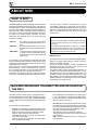
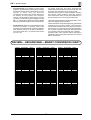
DB-3
User Manual
WARNING: READ THIS FIRST!
WARNING
RISK OF ELECTRIC SHOCK
DO NOT OPEN
AVIS
RISQUE DE CHOC ÉLECTRIQUE
NE PAS OUVRIR
This symbol is intended to alert the user to the
presence of uninsulated “dangerous voltage”
within the product’s enclosure that may be of
sufficient magnitude to constitute a risk of
electric shock to persons.
This symbol is intended to alert the user to
the presence of important operating and
maintenance (servicing) instructions in the
literature accompanying the appliance.
CAUTION
TO REDUCE THE DANGER OF ELECTRIC SHOCK
DO NOT REMOVE COVER (OR BACK)
NO USER-SERVICEABLE PARTS INSIDE
REFER SERVICING TO QUALIFIED SERVICE PERSONNEL
“INSTRUCTIONS PERTAINING TO A RISK OF FIRE,
ELECTRIC SHOCK, OR INJURY TO PERSONS”
IMPORTANT SAFETY INSTRUCTIONS
WARNING:
1) Read these instructions.
2) Keep these instructions.
3) Heed all warnings.
4) Follow all instructions.
5) Do not use this apparatus near water.
6) Clean only with dry cloth.
7) Do not block any ventilation openings. Install in accordance with the manufacturer’s instructions.
8) Do not install near any heat sources such as radiators, heat registers, stoves,
or other apparatus (including amplifiers) that produce heat.
9) Do not defeat the safety purpose of the polarized or grounding-type plug. A polarized plug has two blades with one
wider than the other. A grounding type plug has two blades and a third grounding prong. The wider blade or the third
prong are provided for your safety. If the provided plug does not fit in to your outlet, consult an electrician for replacement
of the obsolete outlet.
10) The socket-outlet shall be installed near the equipment and shall be easily accessible.
11) Protect the power cord from being walked on on pinhead, particularly at plugs, convenience receptacles,
and the point where they exit form the apparatus.
12) Only use attachments/accessories specified by the manufacturer.
13) Use only with the cart, stand, tripod, bracket, or table specified by
the manufacturer, or sold, with the apparatus.
When a cart is used, use caution when moving the cart/apparatus
combination to avoid injury from tip-over.
14) Unplug this apparatus during lightning storms or when unused for long periods of time.
15) Refer all servicing to qualified service personnel. Servicing is required when the apparatus has been damaged
in any way, such ad power-supply cord or plug is damaged, liquid has been spilled or objects have fallen into
the apparatus, the apparatus has been exposed to rain or moisture, does not operate normally, or has been dropped.
SAVE THESE INSTRUCTIONS
DB-3 Drawbar Organ
CONTENTS
1. Important notes ....................................................................................................... 31
1.1 Notes on the DB-3 .......................................................................................... 31
1.2 Notes about the manual.................................................................................. 31
2. Introduction ............................................................................................................. 32
3. Controls and connectors ........................................................................................ 33
3.1 The front panel ............................................................................................... 33
3.2 The rear panel ................................................................................................ 35
3.3 Connection examples ..................................................................................... 36
4. Using the memories and drawbars........................................................................ 37
4.1 The Global Memories ..................................................................................... 37
4.2 The Upper Memories ...................................................................................... 38
4.3 The Bass & Lower Presets ............................................................................. 38
4.4 Creating a sound with the drawbars ............................................................... 39
4.5 Factory Settings .............................................................................................. 39
5. Setting the Lower and Bass sections .................................................................... 40
6. Percussion ............................................................................................................... 43
7. The effects ............................................................................................................... 44
7.1 Vibrato & Chorus ............................................................................................ 44
7.2 Reverb ............................................................................................................ 44
7.3 Overdrive ........................................................................................................ 45
7.4 Rotary ............................................................................................................. 45
8. Additional functions ................................................................................................ 47
8.1 The equalizer .................................................................................................. 47
8.2 Adding the internal noises .............................................................................. 47
8.3 Scaling ............................................................................................................ 48
8.4 Adding the click ............................................................................................... 48
9. MIDI ........................................................................................................................... 49
9.1 Setting the MIDI functions ............................................................................... 49
9.2 Regulating the MIDI dynamic value (keyboard version only) .......................... 53
About MIDI ................................................................................................................... 54
What is MIDI? ....................................................................................................... 54
Main MIDI messages transmitted and received by the DB-3 ................................ 54
Decimal-exadecimal-binary conversion chart ....................................................... 55
Detailed MIDI implementation ............................................................................... 56
MIDI implementation chart .................................................................................... 60
29
DB-3 Drawbar Organ
1. IMPORTANT NOTES
1.1 NOTES ON THE DB-3
LOOKING AFTER THE PRODUCT
•
•
•
•
•
•
•
Do not apply excessive force to the structures or the controls (knobs, switches, etc.).
Handle the instrument with care during both transport and use. The instrument should
be transported in its original packaging or a similar container.
Do not place the instrument close to heat sources, in damp or dusty places or in the
vicinity of strong magnetic fields. Do not expose the instrument to direct sunlight.
When possible, do not place the instrument close to units which generate strong
interference, such as radios, TVs, computer videos, etc.
Never insert foreign bodies inside the instrument or pour liquids of any kind into it.
For cleaning, use only a soft brush or compressed air; never use detergents, solvents
or alcohol.
The instrument contains a buffer battery allowing retention of the data in the RAM
memory. The lifetime of this battery is normally 3 years; for replacement, contact a
specialist service centre, taking care to transfer the programming settings onto a MIDI
unit able to memorise System Exclusive messages.
CONNECTION TO THE ELECTRICAL MAINS
•
•
•
Use the external power supply adapter supplied with the instrument only.
To avoid the risk of electric shock, never make connections with wet hands.
Make sure that the mains voltage is the same as that marked on the power supply
adapter.
CONNECTING TO OTHER INSTRUMENTS
•
•
Always use good quality screened cables. When disconnecting cables from sockets,
always take hold of the connector and not the cable itself; when winding cables, do not
knot or twist them.
Before making the connections ensure that the other units (especially amplification
and speaker systems) you are about to connect are switched off. This will prevent
noisy or even dangerous signal peaks.
1.2 NOTES ABOUT THE MANUAL
•
•
•
Take good care of this manual.
This manual constitutes an integral part of the instrument. The descriptions and
illustrations in this publication are not binding.
While the instrument’s essential characteristics remain the same, the manufacturer
reserves the right to make any modifications to parts, details or accessories considered
appropriate to improve the product or due to requirements of a construction or
31
DB-3 Drawbar Organ
•
•
•
•
commercial nature, at any time and without undertaking to update this publication
immediately.
All rights reserved; the reproduction of any part of this manual, in any form, without the
manufacturer’s specific written permission is forbidden.
Read all the information described carefully. You will avoid wasting time and will obtain
the best performance from your instrument.
The codes or numbers in square brackets ([]) indicate the names of the buttons, sliders
or trimmers on the instrument control panel.
For example, “[REVERB]” refers to the REVERB trimmer.
The illustrations and display pages are purely guideline and may differ from those
actually shown on the LCD.
2. INTRODUCTION
In an electromagnetic organ, the sound is generated by 91 notched and 5 smooth wheels
turning close to a magnet with a winding.
The notches in the wheels (known as tonewheels) cause variations in the magnetic field,
which generate a voltage and therefore a signal which, controlled by the drawbars and
amplified, becomes sound.
But the tonewheels and the drawbars are not the only factors behind these organs’ special
sound; there are also many other ingredients, such as the click of the manual contacts,
the background noise due to the motor inside (needed to turn the tonewheels) and, last
but not last, the external rotary speaker which gives another special quality to the timbre.
These are just some of the characteristics of the electromagnetic organ, which has played
an important role in the history of music.
The Viscount DB-3 is able to simulate all these characteristics thanks to the new technology
known as A.S.T.M. (Advanced Synchronous Tonewheel Modelling).
This new, innovative synthesising technology considers all the factors which affect the
sound of the original organs, such as the perfect synchronisation of the tonewheels, the
cabinet (including its size and the type of wood), the imperfections of the electrical circuits,
the motor noise, and so on.
Moreover, you will be able to achieve an almost perfect simulation (whatever people may
say, it is impossible to reproduce the exact sound of a real organ) of the combination of the
organ and speaker, thanks to the TONE CABINET EMULATION technology, which provides
an optimal reproduction of all the resonance characteristics of the cabinets used for this
special type of amplifier.
32
DB-3 Drawbar Organ
3. CONTROLS AND CONNECTORS
3.1 THE FRONT PANEL
1
8
7
2
3
4
5
6
1. VOLUME & CONTROL Section: this contains four trimmers for control of:
-
[MASTER]: the instrument’s general volume.
[REVERB]: the total reverb effect.
[OVERDRIVE]: the amount of the distortion effect.
[VIBRATO & CHORUS]: selection of the type of Vibrato (V1, V2 or V3) or Chorus
(C1, C2 or C3).
2. SETTINGS Section: this section contains the buttons used to recall and regulate the
display functions. These buttons allow you to set:
-
[BASS]: the parameters relating to the Bass section.
[LOWER]: the parameters relating to the Lower section.
[ROTARY]: the setting of the Rotary effect.
[REV.TYPE]: selection of the type of reverb.
[EQUALIZER]: equalizer setting.
[MIDI]: settings concerning the MIDI functions.
[GLOBAL MEMORY]: selection of the Global Memories.
[VALUE]: increases ([+] button) or decreases ([-] button) the value of the
parameter shown on the display.
[BASS] + [LOWER] (Noise): adjustment of the levels of the Motor Noise and
Leakage Noise.
[LOWER] + [ROTARY] (Scaling): selection of the Scaling curves.
[REV.TYPE] + [EQUALIZER] (Click): adjustment of the effect which simulates
the click of the manual contacts in the original electromagnetic organs.
[EQUALIZER] + [MIDI] (Key Touch): (version with manual only) selection of
the dynamic curve transmitted by MIDI.
33
DB-3 Drawbar Organ
Interpretation of the display pages is easy and intuitive. After selecting a given group
of functions using the SETTINGS buttons, you simply press the same button again to
scroll on to the next display page.
Since the display pages have a cyclic structure, to recall a video page already displayed,
just keep pressing the button of the group of functions selected until the page you
require appears.
If you press the button of another group of functions, the video page required will be
displayed at once.
3. PERCUSSION Section: this section contains the buttons for activating and adjusting
the percussion.
-
[NORM/SOFT]: selection of the percussion level.
[SLOW/FAST]: selection of the percussion decay time.
[2nd]: activation of the second harmonic percussion.
[3rd]: activation of the third harmonic percussion.
4. VIBRATO & CHORUS Section: these two buttons allow you to enable the Vibrato or
Chorus effect selected with the [VIBRATO & CHORUS] switch in the VOLUME &
CONTROL section, on the Lower ([LOWER] button) and/or Upper ([UPPER] button)
sections of the keyboard.
5. BASS & LOWER PRESET Section: these buttons allow you to activate the presets of
the Bass section ([BASS.x] buttons) and/or of the Lower section ([ORG.x] buttons).
6. ROTARY Section: this section contains the buttons for controlling the Rotary effect,
as follows:
-
[ON]: switches on the Rotary effect (LED on). When the LED is off the Rotary
effect is deactivated.
[FAST]: selects the Fast speed of the Rotary effect (LED on). When the LED is
off, the Slow speed is activated.
7. UPPER MEMORY Section: these buttons allow you to recall one of the 6 memories
relating to the Upper section. You can also use the [DRAWBARS] button to regulate
the sound using the drawbars.
This button can also be used to save an Upper Memory (point 4.2).
8. Drawbars: these drawbars can be used to set the timbre with which you wish to play
in manual mode when the LED of the [DRAWBARS] button is on or after a Global and/
or Upper Memory selection.
34
DB-3 Drawbar Organ
3.2 THE REAR PANEL
1
2
3
4
5
6
1. [POWER ] Switch: instrument on/off switch.
2. [AC ADAPTOR] connector: socket for connecting the external power supply adapter
supplied with the instrument.
3. PEDAL Jacks: these Jacks allow you to connect the pedals for controlling:
-
[SLOW/FAST]: the speed of the Rotary effect (footswitch pedal).
[MEMORY]: cyclic selection of the last Upper Memory selected or of the manual
drawbar setup (footswitch pedal).
[VOLUME]: the instrument’s general volume (swell pedal).
4. [PITCH] Trimmer: this control allows you to regulate the instrument’s fine tuning. In
the central position, A is 440 Hz.
5. MIDI Connectors: five-pin DIN sockets for connecting remote MIDI units, as follows:
-
[MIDI IN]: connector for receiving MIDI messages from a remote unit.
[MIDI OUT]: connector for transmitting the MIDI messages generated by the
DB-3.
[MIDI THRU]: connector for transmitting the MIDI messages received by the
[MIDI IN ] port.
6. OUTPUT Jacks: the [L/Mono] and [R] jacks allow you to connect the instrument to an
amplification system, speakers with amplifier or mixers. To use a monophonic signal,
connect to the [L/Mono] jack only. The [HEADPHONES] jack allows you to connect a
headphone set.
35
DB-3 Drawbar Organ
3.3 CONNECTION EXAMPLES
36
DB-3 Drawbar Organ
4. USING THE MEMORIES AND DRAWBARS
4.1 THE GLOBAL MEMORIES
The Global Memories are main memories allowing you to save all the Upper memories
and all the instrument’s internal parameters except for the MIDI settings, the [MASTER]
volume, and the fine tuning ([PITCH] trimmer on the rear panel).
At switch-on, the instrument will automatically recall the latest selected Global Memory:
and the LED of the [DRAWBARS] button will come on, informing you that you can control
the sound with the drawbars.
You can use the VALUE [+] and [-] buttons to select another Global Memory, then press
[GLOBAL MEMORY] to activate it.
To recall a Global Memory while the display is showing another function (such as the
Equalizer), simply press the [GLOBAL MEMORY] button, the VALUE keys to make the
selection, and [GLOBAL MEMORY] another time.
To save a memory keep pressed the [GLOBAL MEMORY] key: the number of the memory
shown on the display will start to flash, informing you that you can use the VALUE buttons
to select another memory in which to save the current setup. To save the setup, press
[GLOBAL MEMORY] again, or to abort the procedure press another button in the
SETTINGS section.
WARNING!
Bear in mind that when you overwrite a memory the data it already contained will be lost. To restore the
memories present when the instrument was purchased, use the Factory Settings function described in point
4.5.
37
DB-3 Drawbar Organ
4.2 THE UPPER MEMORIES
The Upper Memories allow you to recall one of the six memories relating to the Upper
section. Unlike the Global Memories, in these memories it is only possible to save the
drawbar setting.
To activate the memory you require, press its button and the DB-3 will recall its contents
immediately, and then illuminate the LED button.
As well as the memory selection keys, there is also a [DRAWBARS] button for activating
the Drawbar manual operating mode described in point 4.4 “Creating a sound with the
Drawbars”.
To save a drawbar setup in a memory, simply press the [Store] button and keep it pressed
(the LED starts flashing) while you press the key of the memory of your choice.
WARNING!
Bear in mind that when you overwrite a memory the data it contains will be lost. To restore the memories
present when the instrument was purchased, use the Factory Settings function described in point 4.5.
4.3 THE BASS AND LOWER PRESETS
The Bass and Lower Presets are non-modifiable memories you can use to recall a preset
drawbar setup programmed in our workshops.
To select the Preset you require simply press its key: the LED will come on to confirm the
selection.
The [BASS 1] and [BASS 2] buttons allow you to recall the Presets of the Bass section.
The [ORG.1], [ORG.2], [ORG.3], [ORG.4] and [ORG.5] buttons are Presets relating to the
Lower section.
38
DB-3 Drawbar Organ
4.4 CREATING A SOUND WITH THE DRAWBRAS
The drawbars allow you to set the
timbre of the Upper section.
When completely retracted into
the organ (i.e. when none of the
numbers on the bar can be seen),
a drawbar is deactivated; as it is
gradually pulled out, the various
volume levels (numbered from
one to eight on the bar) of the
harmonic associated to the
drawbar concerned are obtained.
The DB-3 set of drawbars
consists of four white, three black and two brown drawbars. The colour of the drawbar
indicates the type of harmonic, naturally referred to the equal temperament system: white
for the fundamental, second, fourth and eighth harmonic (octave intervals); black for the
twelfth, seventeenth and nineteenth harmonic, and brown for the octave below the
fundamental and its harmonic third.
The drawbars are marked with the length in feet of the church organ pipes used to create
the notes. The pipe which produced the fundamental was 8 feet long; when it was shortened
by one half (4 feet) a note one octave higher was obtained, while if its length was doubled
(16 feet) the octave below was obtained.
To play with the real settings of the drawbars (i.e. not with the Upper Memory settings),
press the [DRAWBARS] button. The LED of the button will come on to confirm the selection.
4.5 FACTORY SETTINGS
The Factory Settings procedure allows you to perform a general reset of the instrument
and restore the settings present when it was purchased.
To do this, switch on the DB-3 with the VALUE [+] and [-] buttons pressed; the LED of
[GLOBAL MEMORY] will start to flash and the display will show:
Press [GLOBAL MEMORY] to complete the procedure, or press any other button to annul
the Factory Settings function, leaving the instrument’s current settings unchanged (in the
both case the instrument will perform an automatic reboot to restore the current values of
the parameters).
39
DB-3 Drawbar Organ
5. SETTING THE LOWER AND BASS
SECTIONS
The DB-3 allows you to simulate the two manuals (Upper and Lower) and the pedal board
(Bass) of the original electromagnetic organs by dividing the keyboard (the one of the
Keyboard version or a Master Keyboard connected to the Expander version) into zones
by means of split points.
As well as this, you can set the operating modes of the Bass section (Layer or Split),
programme any split points, the levels, and so on.
To access the Bass section setting video pages, simply press the [BASS] button in the
SETTINGS section; the display will show the first video page, for setting the volume.
Use the VALUE [+] and [-] buttons to set the value required.
Press the [BASS] button again to display the second programming video page:
You can use this parameter to set the value of the Sustain function, meaning the time for
which a note will continue to sound even after the keyboard key has been released.
To display the third video page press [BASS] again; the setting of the bass section operating
mode will be displayed:
If you set “L” the bass will play in Layer mode, i.e. in addition to the Upper or Lower
sections, up to the split point set. In this case, the bass will also play in mono mode.
Otherwise, if “S” (Split) is set the display will shows the video page described in the next
page.
40
DB-3 Drawbar Organ
With this setting you will only be able to play the Bass voices in the keyboard range
assigned to the bass.
KEYBOARD CONFIGURATION EXAMPLES
Use the VALUE [+] and [-] buttons to set the desired mode.
The fourth video page (displayed by pressing [BASS] again) allow you to set the split point
of the Bass section.
To do this press VALUE [+] button, the display will show (flashing) the current key setted
as split point. Now press the desidered key on the keyboard to set it as new split.
Since the Bass section must always be within the C2 and B3 keys range, if a nonvalid split point is set the setting will be rejected and the display will continue to show the
current video page.
If the setting is acceptable, the display will show the new split point then will return to the
previous video page.
41
DB-3 Drawbar Organ
As for the bass, you can use the display to regulate the volume and the split point of the
Lower section.
To do this, press the [LOWER] button; the display will show the current volume value:
Use the VALUE [+] and [-] buttons to set the value required.
Pressing [LOWER] button again the display will show the video page to set the desidered
split point.
To do this press VALUE [+] button, the display will show (flashing) the current key setted
as split point. Now press the desidered key on the keyboard to set it as new split.
After this the display will show the new split point then will return to the previous video
page.
N.B.
Setting the split points (Lower and Bass) using MIDI, remember that the minimun split point is C2.
Any lowest note, therefore, will set the split point as C2.
42
DB-3 Drawbar Organ
6. PERCUSSION
The percussion, an effect typical of the electromagnetic
organ, provides a repetition of a harmonic added to those
preset using the drawbars, with quick attack and
exponential decay.
In the original instrument, the sound produced by the 1' drawbar was eliminated when the
percussion was activated: the DB-3 also reproduces this feature.
For activating the percussion feature, there are two buttons in the PERCUSSION section
of the front panel marked [2nd] and [3rd].
The [2nd] button activates the percussion one octave above the fundamental note you are
playing, while the [3rd] button adds the percussion one thirteenth above the fundamental.
N.B.
The [2nd] and [3rd] buttons are self-disabling. It is therefore not possible to use the two percussion options
simultaneously
The volume of the percussion can also be regulated using the [NORM/SOFT] switch.
When the LED of the key is off, the volume of the percussion will be normal; when [NORMAL/
SOFT] is pressed the LED comes on and the volume of the percussion will be reduced.
You can use the [SLOW/DECAY] button to set the percussion decay time in both modes.
When the LED of the key is off, the decay time will be standard, while when [SLOW/
DECAY] is pressed the LED will light up and the decay time will be reduced, giving a
“shorter” percussion effect.
43
DB-3 Drawbar Organ
7. THE EFFECTS
7.1 VIBRATO & CHORUS
The [VIBRATO & CHORUS] selector in the VOLUME & CONTROL section
allows the Vibrato or Chorus effect of choice to be added to the sound.
The Vibrato modulates the pitch of the signal in cyclic mode, while the
Chorus is the sum of the direct sound and the modulated sound, so that
the signal width is also modulated.
You can use the six-setting knob to select one of the three Vibrato effects (V1-V2-V3) or
the three Chorus effects (C1-C2-C3), which vary in the depth and speed of the signal
modulation.
You can use the [UPPER] and [LOWER] buttons in the VIBRATO &
CHORUS section to assign the effect selected to the two sections of
the keyboard respectively.
The LED on the key will illuminate to show that the effect has been
assigned.
7.2 REVERB
The reverb derives from the sum of the various acoustic reflections generated
by a sound in a natural environment. When you clap your hands in a large,
reflective building, such as a church, you will hear a loud resonance which
gradually fades away.
In the original electromagnetic organs, the reverb was simulated by means of
a special device containing one or more springs.
The Reverb effect of the DB-3 allows you to simulate various types of natural reverbs, and
the reverb characteristic of this particular instrument.
You can use the [REVERB] trimmer in the VOLUME & CONTROL section to regulate the
amount of reverb effect required. Pressing the [REV.TYPE] button in the SETTINGS section
allows you to choose the type of reverb.
You can then use the VALUE [-] and [+] buttons to select the other reverbs described on
the next page.
44
DB-3 Drawbar Organ
-
Hall: reverb of a very large room
Room: reverb of an average-size room
Church: reverb typical of a church
Spring: reverb produced by the spring system
Delay: echo effect
7.3 OVERDRIVE
This effect simulates the distortion of a signal when the valve amplifier
connected to the organ is brought to saturation.
The Overdrive of the DB-3 faithfully reproduces the sound qualities and
characteristics of analogue distortion, which increased in direct proportion to
the signal entering the amplifier.
You will therefore note that the DB-3 effect depends on a large number of factors including
the general volume, the level and number of drawbars open, and the number of notes
played (at low volumes, a lot of notes have to be played to bring the signal to saturation
level).
You can use the [OVERDRIVE] trimmer to regulate the quantity of distortion you require.
7.4 ROTARY
The Rotary of the DB-3 simulates the characteristic effect produced by
a rotary amplifier connected to the organ.
This system established itself with the advent of the electromagnetic
organ, and consisted of two sections, one for the high tones and the
other for the low tones, which were able to turn at different speeds.
The DB-3 effect allows the most faithful possible simulation of both the continuous variations
in tone caused by the different rotation of the speakers and (thanks to the TONE CABINET
EMULATION technology) the special resonances generated inside the cabinet.
You can use the [ON] button in the ROTARY section to activate (LED on) or deactivate
(LED off) this effect, and the [FAST] key to select the rotation speed. When the LED is on,
the Fast speed is set.
45
DB-3 Drawbar Organ
The parameters on the display also allow you to set the two rotation speeds and the
transients, meaning the switch times between low and high speed and vice-versa.
To display these parameters, press the [ROTARY] button in the SETTINGS display; the
display will show:
This first video page allows you to set the low speed (using the VALUE buttons). The
value “b” stands for Brake, meaning rotary speaker stationary (although the cabinet tone
simulation is still present), while the numbers from 2 to 9 indicate the speeds.
When [ROTARY] is pressed again the parameter for regulating the Fast speed will be
displayed:
and, when [ROTARY] is pressed again, the time for switching from the Slow to the Fast
speed (also known as Rise Time):
and the time for switching from the Fast to the Slow speed (Fall Time):
In both video pages, use the VALUE [+] and [-] buttons to set the values you require.
ROTARY DIAGRAM
46
DB-3 Drawbar Organ
8. ADDITIONAL FUNCTIONS
8.1 THE EQUALIZER
Pressing the [EQUALIZER] button in the SETTINGS section allows you to regulate the
equalizer provided on the DB-3.
The first video page displayed allows regulation of the attenuation (negative values) or
enhancement (positive values) of the low frequencies.
As for all the other video pages, use the VALUE buttons to set the value required.
When the [EQUALIZER] button is pressed again, the system will show the video page for
regulating the high frequencies:
8.2 ADDING THE INTERNAL NOISES
To make the sound of the DB-3 as faithful a reproduction as possible of that of the
original electromagnetic organs, you can use the Noise function to add the organ’s internal
noise.
In actual fact, the noises reproduced are of two types: Motor Noise, or the noise generated
by the internal motor used to rotate the 91 tonewheels, and the Leakage Noise, generated
by the rotation of the wheels themselves.
To regulate the Leakege Noise press the [LOWER] button keeping pressed the [BASS]
button (both in the SETTINGS section):
Press again the [LOWER] button keeping pressed the [BASS] button to regulate the Motor
Noise (the video page is showed in the next page).
47
DB-3 Drawbar Organ
In both video pages, use the VALUE buttons to set the noise level required.
8.3 SCALING
The Scaling function allows you to select four variations in the instrument’s character, to
further customise the sound of the DB-3.
To select this video page, press the [ROTARY] button holding pressed the [LOWER] button:
Use the VALUE buttons to select the desidered Scaling.
8.4 ADDING THE CLICK
Like the background noise, the click is a feature typical of electromagnetic organs.
Generated by flaws in the electronic circuit, which provided anomalous amplification of
the voltage from the drawbar buses, this defect actually proved popular with most musicians
because it provides a more pronounced attack.
As for the other effects, the DB-3 also allows emulation of this characteristic.
To display the click setting video page, press the [EQUALIZER] button keeping pressed
the [REV.TYPE] button:
Here again, regulate the level of the click using the VALUE buttons.
48
DB-3 Drawbar Organ
9. MIDI
9.1 SETTING THE MIDI FUNCTIONS
You can press the [MIDI] button to show the video pages relating to the MIDI settings on
the display. For a more detailed description of the MIDI messages transmitted and received
by the DB-3, please consult the “Detailed MIDI Implementation” section on page 56.
The first video page displayed allows setting of the MIDI Mode to be used to receive and
transmit the messages.
You can use the VALUE [+] and [-] buttons to select the MIDI Mode you require from the
following options:
-
MIDI Mode 1 (Md1 on display): the instrument receives and transmits on just one
MIDI channel (the one of the Upper section, which can be set using the video page
displayed by pressing [MIDI] again). The notes received are played on the Upper,
Lower and Bass sections in accordance with the split settings in the instrument.
-
MIDI Mode 2 (Md2): the instrument receives and transmits on two channels (those
of the Upper and Lower sections, which can be set by pressing the [MIDI] button).
In reception, the notes on the channels of the Upper and Lower sections can be
received across the entire keyboard range of the DB3, while the Bass section will
play on the basis of its split point.
49
DB-3 Drawbar Organ
-
MIDI Mode 3 (Md3): the instrument receives and transmits on three channels (those
of the Upper, Lower and Bass sections). In reception, the notes on the channels of
the Upper and Lower sections can be received across the entire keyboard range of
the DB3, while the Bass section will play up to its maximum permitted range (key
B3).
N.B.
ü In the diagrams shown in the previous page, the Bass section is in Split mode.
ü Any note, received by the MIDI IN port, not included in the OB-3’s keyboard range (C2-C7) will be
shifted up (if below of C2) or down (if above of C7) of one octave.
Pressing the [MIDI] button again allows you to display the video pages for setting the
channels for receiving and transmitting the MIDI data for the Upper sections:
Lower (can only be displayed with MIDI Modes 2 and 3):
and Bass (can only be displayed with MIDI Mode 3):
To select the channel required use the VALUE [+] and [-] buttons.
50
DB-3 Drawbar Organ
When the [MIDI] button is pressed again, the video page for setting the Control Mode will
be displayed; this is the mode for transmission and reception of MIDI message relating to
the operating parameters.
The Control Mode can be set as:
-
Sys-Ex (CmS on display): the internal parameters are regulated by means of system
exclusive messages.
Control Change (CmC on display): some internal parameters (Reverb, Rotary and
Drawbars) are regulated by means of standard Control Changes to provide simple,
immediate control by means of the instrument connected by MIDI (a master
keyboard, for example).
N.B.
The Volume and Expression (expression pedal connected to the rear [VOLUME] socket) parameters are
transmitted by means of Control Changes, regardless of the Control Mode settings.
The next video page (displayed pressing [MIDI] button) allows you to transmit a Program
Change message on the channel of the Upper section:
Pressing VALUE [+] button the display will show the Program Change 1.
With the VALUE buttons you can select the desired PG, then press [MIDI] button to transmit
the message.
The last video page in the MIDI menu allows you to transmit all the instrument’s internal
programming by means of system exclusive messages (MIDI Bulk Dump).
51
DB-3 Drawbar Organ
To carry out a Bulk Dump correctly, connect the DB-3 to a Personal Computer or a remote
sequencer (see diagrams below). If you are using a PC, you will need MIDI software
capable of recording and saving the MIDI data received on the audio card on the hard
disk. Start recording on the PC or sequencer (there is normally a REC button provided for
this purpose) and then press the VALUE [+] button on the DB-3 (the display will show
three lines). Once the Bulk Dump is complete the display will show the “Mdb” video page,
then stop the recording (there is normally a STOP button for this purpose) and save all the
data on the PC hard disk / floppy disk or in the sequencer’s memory / floppy disk.
To reload the data in the DB-3, after opening the file using the MIDI software (in the PC),
start reading the file (normally using the PLAY button). The DB-3 will automatically save
the data in its internal memory.
MIDI CONNECTION EXAMPLE TO RECORD A BULK DUMP
MIDI CONNECTION EXAMPLE TO RELOAD A BULK DUMP
52
DB-3 Drawbar Organ
9.2 REGULATING THE MIDI DYNAMIC VALUE
(keyboard version only)
As in the original electromagnetic organs, the DB-3 generates the sound with fixed dynamic.
However, the Key Touch function allows you to select a dynamic curve or value to be
transmitted by MIDI, to allow control of any expanders connected.
To access this function, press [MIDI] button holding pressed [EQUALIZER]; the display
will show the first dynamic curve activated:
You can use the VALUE [+] and [-] buttons to select the curve of your choice, which will be
activated automatically.
The curves available are:
-
KEY TOUCH 1 (To1 on display): “Light” curve with which it is easy to reach high
dynamic values.
KEY TOUCH 2 (To2): “straight” curve
KEY TOUCH 3 (To3): “Heavy” curve with which it is difficult to reach high dynamic
values.
KEY TOUCH 4 (To4): dynamic set permanently at 64.
KEY TOUCH 5 (To5): dynamic permanently set at 126.
53
DB-3 Drawbar Organ
ABOUT MIDI
WHAT IS MIDI?
The same type of transfer of information is used to
record MIDI sequences. A sequencer can be used to
record the MIDI data transmitted by the DB-3 or any other
instrument. When these recorded data are sent to the
DB-3, it will automatically play back the recorded
performance.
The MIDI (Musical Instrument Digital Interface) allows
instruments of different makes and types to communicate
with each other by means of this clearly specified protocol
of codes. This makes it possible to create systems of
MIDI instruments which offer much better versatility and
control than can be achieved with separate instruments.
To make this communication possible, all MIDI
instruments are equipped with two or three 5 pin DIN
connectors marked:
- MIDI IN:
- MIDI OUT:
- MIDI THRU:
CAUTIONS
Always use top quality cables for the MIDI connections from and
to the DB-3. We also advise the use of cables no more than 5
metres long.
It is possible to use the MIDI THRU to connect two or more MIDI
devices, but in practice the limit is 5 units. This is because as the
signal path becomes longer, the signal deteriorates and the
messages can no longer be received correctly.
By means of this jack, the device
receives the MIDI data emitted by other
units.
By means of this jack the device sends
the MIDI data it has generated to other
units.
This jack, used to connect several units
in series, emits the MIDI data exactly
as they are received by the respective
MIDI IN port.
MIDI Channels
The MIDI is able to transmit a multitude of digital data by
means of a single cable and thus a single connector,
thanks to the MIDI channels.
There are 16 MIDI channels, so MIDI messages are
processed when the channels of the receiver and
transmitter instruments are the same.
The DB-3 is able to receive and transmit information on
a maximun of 3 MIDI channels simultaneously: one for
the upper manual, one for the lower manual and one for
the BASS section (see also MIDI Mode function). The
data relating to the instrument’s general information (the
Reverb parameter, for example) are sent on the channel
associated to the upper manual.
For example, most instruments equipped with MIDI
interface transmit MIDI messages which specify which
note has been played and with what dynamics by means
of the MIDI OUT connector.
If this connector is connected to the MIDI IN of another
MIDI instrument, such as a synthesiser or an expander,
the connected instrument will give a precise response
to the notes played on the transmitter instrument.
This allows you actually to play two instruments at the
same time, and obtain special multi-instrument sounds.
MAIN MIDI MESSAGES TRANSMITTED AND RECEIVED BY
THE DB-3
The MIDI includes various types of messages used to
communicate various types of data. The MIDI messages
can be subdivided into messages handled separately
on each channel, and messages dedicated to the entire
system.
Note messages are expressed as a number from 0
to 127, with Middle C represented by the number
60. Since its dynamic value is fixed, the OB5 always
sets the Velocity value as 64.
•
The channel messages include:
•
Note On: this message is transmitted when a note
is played, i.e. when a keyboard key is pressed. Each
Note On message includes the following codes:
Note On: when a key has been pressed;
Note Number: the key and thus the relative note
which has been played;
Velocity: dynamic of the note (the force with which
the key had been pressed).
54
Note Off: this message is transmitted when the key
pressed previously is released. When it is received,
the sound of the note of that key is deactivated. Each
Note Off message includes the following codes:
Note Off: a key has been released;
Note Number: which key has been released;
Velocity: dynamic (amount of force) with which it has
been released.
N.B.: A Note On message with Velocity=0 is considered as a
Note Off message.
DB-3 Drawbar Organ
•
•
Program Change: this message is used to select
programs, given that many instruments have a large
number of memories, each corresponding to a given
program or timbre. Once you know the
correspondence between the number assigned to
the memory and the number of the Program
Change, you will be able to select the type of sound
you desire. To transmit Program Changes from the
DB-3, you will be able to select the memories (Global
Memory, Upper Memory, Bass and Lower Presets).
As already mentioned, the system messages are
independent of the subdivision of the channels, and once
processed, they take effect on the entire system.
There are various types of system messages, including
the exclusive system messages (SYS-EX), meaning
those instructions which can only be interpreted by a
device identical to the one which generated them.
These messages include the BULK DUMP data, i.e. the
instrument programming instructions.
These instructions contain the programming parameters
normally saved in a memory location. They are used to
transfer these parameters from one device to another of
the same type, or to save them on a remote memorisation
unit, such as a computer or sequencer, which allows them
to be restored if they are accidentally lost or deleted.
Another function of the exclusive system messages is
identification of the transmitter instrument if the receiver
device requests this.
Control Change: these are control messages (often
associated to sliders or pedals) used to add
expression to the performance, by allowing definition
(and real-time control) of the timbre parameters,
such as the volume (CC n.7) or the amount of reverb
(CC n.91), etc.
DECIMAL - HEXADECIMAL - BINARY CONVERSION CHART
DECIMAL
0
1
2
3
4
5
6
7
8
9
10
11
12
13
14
15
16
17
18
19
20
21
22
23
24
25
26
27
28
29
30
31
32
33
34
35
36
37
38
39
40
41
42
HEXADECIMAL
00
01
02
03
04
05
06
07
08
09
0A
0B
0C
0D
0E
0F
10
11
12
13
14
15
16
17
18
19
1A
1B
1C
1D
1E
1F
20
21
22
23
24
25
26
27
28
29
2A
BINARY
0000 0000
0000 0001
0000 0010
0000 0011
0000 0100
0000 0101
0000 0110
0000 0111
0000 1000
0000 1001
0000 1010
0000 1011
0000 1100
0000 1101
0000 1110
0000 1111
0001 0000
0001 0001
0001 0010
0001 0011
0001 0100
0001 0101
0001 0110
0001 0111
0001 1000
0001 1001
0001 1010
0001 1011
0001 1100
0001 1101
0001 1110
0001 1111
0010 0000
0010 0001
0010 0010
0010 0011
0010 0100
0010 0101
0010 0110
0010 0111
0010 1000
0010 1001
0010 1010
DECIMAL
43
44
45
46
47
48
49
50
51
52
53
54
55
56
57
58
59
60
61
62
63
64
65
66
67
68
69
70
71
72
73
74
75
76
77
78
79
80
81
82
83
84
85
HEXADECIMAL
2B
2C
2D
2E
2F
30
31
32
33
34
35
36
37
38
39
3A
3B
3C
3D
3E
3F
40
41
42
43
44
45
46
47
48
49
4A
4B
4C
4D
4E
4F
50
51
52
53
54
55
55
BINARY
0010 1011
0010 1100
0010 1101
0010 1110
0010 1111
0011 0000
0011 0001
0011 0010
0011 0011
0011 0100
0011 0101
0011 0110
0011 0111
0011 1000
0011 1001
0011 1010
0011 1011
0011 1100
0011 1101
0011 1110
0011 1111
0100 0000
0100 0001
0100 0010
0100 0011
0100 0100
0100 0101
0100 0110
0100 0111
0100 1000
0100 1001
0100 1010
0100 1011
0100 1100
0100 1101
0100 1110
0100 1111
0101 0000
0101 0001
0101 0010
0101 0011
0101 0100
0101 0101
DECIMAL
86
87
88
89
90
91
92
93
94
95
96
97
98
99
100
101
102
103
104
105
106
107
108
109
110
111
112
113
114
115
116
117
118
119
120
121
122
123
124
125
126
127
HEXADECIMAL
56
57
58
59
5A
5B
5C
5D
5E
5F
60
61
62
63
64
65
66
67
68
69
6A
6B
6C
6D
6E
6F
70
71
72
73
74
75
76
77
78
79
7A
7B
7C
7D
7E
7F
BINARY
0101 0110
0101 0111
0101 1000
0101 1001
0101 1010
0101 1011
0101 1100
0101 1101
0101 1110
0101 1111
0110 0000
0110 0001
0110 0010
0110 0011
0110 0100
0110 0101
0110 0110
0110 0111
0110 1000
0110 1001
0110 1010
0110 1011
0110 1100
0110 1101
0110 1110
0110 1111
0111 0000
0111 0001
0111 0010
0111 0011
0111 0100
0111 0101
0111 0110
0111 0111
0111 1000
0111 1001
0111 1010
0111 1011
0111 1100
0111 1101
0111 1110
0111 1111
DB-3 Drawbar Organ
DETAILED MIDI IMPLEMENTATION
CHANNEL MESSAGES
Note On
-
Message which is generated when a key is pressed.
This message is transmitted by the keyboard version
only.
-
9nH kkH vvH
-
n=MIDI channel number
kk=note number
vv=note on velocity
-
-
-
: 00H – 0FH (ch.1 – ch.16)
: 00H – 7FH (0 – 127)
received
: 24H – 60H (36 – 96)
transmitted
: 01H – 7FH (1 – 127)
: 00H (0) Note Off
In MIDI Mode 1 this message controls the general
volume.
In MIDI Mode 2 if this message is received on the
upper channel, it controls the upper volume. If it is
received on the lower channel, it controls the lower
and bass volumes.
In MIDI Mode 3 this message controls the sections
volume according to the channel setted.
•
Expression (CC 11)
Message which controls the sections expression.
BnH 0BH vvH
n=MIDI channel number
vv=expression value
In MIDI Mode 1 the notes are transmitted and
received using the upper channel only. The received
notes are played according to the split points setted
(see also chapt. 5.2).
In MIDI Mode 2 the notes are transmitted and
received using the upper and lower channels only.
The bass notes are played according to the bass
split point.
In MIDI Mode 3 the notes are transmitted and
received using the upper, lower and bass channels
only. The bass notes are played until the maximun
extension allowed is reached.
-
-
: 00H – 0FH (ch.1 – ch.16)
: 00H – 7FH (0 – 127)
This message is transmitted and received on the
section (Upper, Lower and Bass) channel only.
In MIDI Mode 1 this message controls the upper
expression.
In MIDI Mode 2 if this message is received on the
upper channel, it controls the upper expression. If it
is received on the lower channel, it controls the lower
and bass expression.
In MIDI Mode 3 this message controls the sections
expression according to the channel setted.
•
Note Off
Drawbars level (CC 20 – 21 – 22 – 23 – 24 – 25 –
26 – 27 – 28)
These messages control each drawbar level.
Message which is generated when a key is released.
This message is transmitted as Note On with velocity=0
and by the keyboard version only.
BnH xxH vvH
n=MIDI channel number
xx=drawbar
8nH kkH vvH
9nH kkH 00H
n=MIDI channel number
kk=note number
vv=note off velocity
: 00H – 0FH (ch.1 – ch.16)
: 00H – 7FH (0 – 127)
: 00H – 7FH (0 – 127)
ignored
Control Change
vvH=drawbar level
Messages which control some parameters as volume,
reverb, rotary, etc.
Each type of Control Change message is assigned to a
specific control number.
-
: 00H – 0FH (ch.1 – ch.16)
: 14H (drawbar 16’)
: 15H (drawbar 5’ 1/3)
: 16H (drawbar 8’)
: 17H (drawbar 4’)
: 18H (drawbar 2’ 2/3)
: 19H (drawbar 2)
: 1AH (drawbar 1’ 3/5)
: 1BH (drawbar 1’ 1/3)
: 1CH (drawbar 1’)
: 00H – 7FH (0 – 127)
These messages have to be received on the Upper
channel only.
•
Rotary On / Off (CC 29)
This message controls the Rotary on / off switch.
•
Volume (CC 7)
Message which controls the sections volume.
BnH 1DH vvH
BnH 07H vvH
n=MIDI channel number
vv=volume value
-
n=MIDI channel number
vv=Rotary switch
: 00H – 0FH (ch.1 – ch.16)
: 00H – 7FH (0 – 127)
This message is transmitted and received on the
section (Upper, Lower and Bass) channel only.
-
56
: 00H – 0FH (ch.1 – ch.16)
: 00H – 3FH (Rotary off)
: 40H – 7FH (Roraty on)
In MIDI Mode 1 and 2 if this message is received on
the Lower (MIDI Mode 1 only) and Bass channels it
is ignored.
DB-3 Drawbar Organ
•
Rotary Slow / Fast (CC 30)
This message controls the Rotary fast / slow speeds.
SYSTEM EXCLUSIVE MESSAGES
System Exclusive messages control various parameters
of the DB-3. Some parameters are controlled by sys-ex
messages only (i.e. Vibrato, Chorus, Percussion, etc...).
Drawbars level, Reverb and Rotary parameters are
controlled by the Control Changes (with MIDI
Mode=Control Change, see the previous paragraph to
know the messages) or Sys-Ex (with MIDI Mode=SysEx).
BnH 1EH vvH
n=MIDI channel number
vv=Rotary speeds
-
: 00H – 0FH (ch.1 – ch.16)
: 00H – 3FH (slow speed)
: 40H – 7FH (fast speed)
In MIDI Mode 1 and 2 if this message is received on
the Lower (MIDI Mode 1 only) and Bass channels it
is ignored.
Message Format
•
Reverb level (CC 91)
Message which control the Reverb level.
F0H iiH ddH mmH ccH ppH xxH yyH F7H
F0H
iiH
ddH
mmH
ccH
ppH
xxH
yyH
F7H
BnH 5BH vvH
n=MIDI channel number
vv=Reverb level value
-
: 00H – 0FH (ch.1 – ch.16)
: 00H – 7FH (0 – 127)
In MIDI Mode 1 and 2 if this message is received on
the Lower (MIDI Mode 1 only) and Bass channels it
is ignored.
•
All note off (CC 123)
Terminates all notes currently on for the specific channel.
Parameters controlled by System Exclusive
messages only
BnH 7BH 00H
n=MIDI channel number
: System Exclusive Message status
: Manufacturer ID. Viscount ID is 31H
: Device ID (drawbars organs family ID is 30H)
: Model ID (DB-3 model ID is 02H).
: Command ID
: Parameter ID
: First data byte
: Second data byte (if needed)
: EOX (End Of Exclusive)
•
Ovedrive Level
This message regulates the Overdrive level.
: 00H – 0FH (ch.1 – ch.16)
Program Change
F0H 31H 30H 02H 01H 01H xxH yyH F7H
Messages for Upper Memories, Bass and Lower Presets
selection.
With a combination of Bank Select you can select the
Global Memories.
F0H
31H
30H
02H
01H
01H
xxH
yyH
F7H
CnH mmH
n=MIDI channel number
: 00H – 0FH
(ch.1 – ch.16)
mm=Memory – Preset number : 0AH (Drawbars)
: 0BH – 10H
(Upper Memory 1 – 6)
: 14H
(Lower Preset off)
: 15H – 19H
(Lower Preset 1 – 5)
: 1EH
(Bass Preset off)
: 1FH – 20H
(Bass Preset 1 – 2)
•
Type of Vibrato & Chorus
This message select the type of Vibrato or Chorus.
F0H 31H 30H 02H 01H 05H xxH F7H
F0H
31H
30H
02H
01H
05H
xxH
BnH 00H 01H (Bank Select MSB)
BnH 20H 00H (Bank Select LSB)
CnH mmH
n=MIDI channel number
mm=Global memory number
: Exclusive status
: Viscount ID
: drawbars organ ID
: DB-3 ID
: control on panel
: Overdrive level
: first data byte (00H – 01H)
: second data byte (00H – 7FH)
: EOX
: 00H – 0FH
(ch.1 – ch.16)
: 00H – 05H
(Global Memory 1 – 6)
F7H
57
: Exclusive status
: Viscount ID
: drawbars organ ID
: DB-3 ID
: control on panel
: type of Vibrato & Chorus
: data byte
01H=Vibrato V1
02H=Vibrato V2
03H=Vibrato V3
04H=Chorus C1
05H=Chorus C2
06H=Chorus C3
: EOX
DB-3 Drawbar Organ
•
Vibrato & Chorus on Upper and / or Lower
This message assigns the Vibrato or Chorus effect on
the Upper and / or Lower sections.
•
Reverb Type
This message selects the type of Reverb.
F0H 31H 30H 02H 01H 04H xxH F7H
F0H 31H 30H 02H 01H ssH xxH F7H
F0H
31H
30H
02H
01H
ssH
xxH
F7H
F0H
31H
30H
02H
01H
04H
xxH
: Exclusive status
: Viscount ID
: drawbars organ ID
: DB-3 ID
: control on panel
: Vibrato & Chorus on section
06H=Upper
07H=Lower
: data byte
00H=Vibrato & Chorus on
Upper / Lower OFF
01H=Vibrato & Chorus on
Upper / Lower ON
: EOX
F7H
: Exclusive status
: Viscount ID
: drawbars organ ID
: DB-3 ID
: control on panel
: Reverb Type
: data byte
01H=Hall
02H=Room
03H=Church
04H=Spring
05H=Delay
: EOX
•
Equalizer
This message controls the Equalizer Low and High
frequencies.
•
Percussion Norm. / Soft
This message selects the Normal or Soft Percussion.
F0H 31H 30H 02H 01H ffH xxH F7H
F0H 31H 30H 02H 01H 12H xxH F7H
F0H
31H
30H
02H
01H
12H
xxH
F7H
F0H
31H
30H
02H
01H
ffH
: Exclusive status
: Viscount ID
: drawbars organ ID
: DB-3 ID
: control on panel
: Percussion Norm./Soft
: data byte
00H=Normal Percussion
01H=Soft Percussion
: EOX
yyH
F7H
Parameters controlled by System Exclusive
messages with the Control Mode=Sys-EX
•
Percussion Slow / Fast
This message selects the Slow or Fast Percussion.
•
Drawbars Level
This message controls the drawbars level.
F0H 31H 30H 02H 01H 13H xxH F7H
F0H
31H
30H
02H
01H
13H
xxH
F7H
: Exclusive status
: Viscount ID
: drawbars organ ID
: DB-3 ID
: control on panel
: Percussion Slow/Fast
: data byte
00H=Slow Percussion
01H=Fast Percussion
: EOX
F0H 31H 30H 02H 01H ddH xxH yyH F7H
F0H
31H
30H
02H
01H
ddH
•
Percussion 2nd / 3rd / Off
This message turns on and off the Percussions.
F0H 31H 30H 02H 01H xxH F7H
F0H
31H
30H
02H
01H
xxH
F7H
: Exclusive status
: Viscount ID
: drawbars organ ID
: DB-3 ID
: control on panel
: range of frequencies
09H=Low
0BH=High
: data byte (37H – 49H)
: EOX
: Exclusive status
: Viscount ID
: drawbars organ ID
: DB-3 ID
: control on panel
: Percussion On/Off
14H=Percussion 2nd ON
15H=Percussion 3rd ON
16H=Percussion OFF
: EOX
xxH
yyH
F7H
58
: Exclusive status
: Viscount ID
: drawbars organ ID
: DB-3 ID
: control on panel
: drawbar
36H=16’
37H=5 1/3’
38H=8’
39H=4’
3AH=2 2/3’
3BH=2’
3CH=1 3/5’
3DH=1 1/3’
3EH=1’
: first data byte (00H – 01H)
: second data byte (00H – 7FH)
: EOX
DB-3 Drawbar Organ
•
Reverb Level
This message regulates the Reverb level.
F0H 31H 30H 02H 01H 02H xxH yyH F7H
F0H
31H
30H
02H
01H
02H
xxH
yyH
F7H
: Exclusive status
: Viscount ID
: drawbars organ ID
: DB-3 ID
: control on panel
: Reverb level
: first data byte (00H – 01H)
: second data byte (00H – 7FH)
: EOX
•
Rotary On / Off
This message turns on and off the Rotary effect.
F0H 31H 30H 02H 01H 0EH xxH F7H
F0H
31H
30H
02H
01H
0EH
xxH
F7H
: Exclusive status
: Viscount ID
: drawbars organ ID
: DB-3 ID
: control on panel
: Rotary On/Off
: data byte
00H=Rotary OFF
01H=Rotary ON
: EOX
•
Rotary Slow / Fast
This message selects the Rotary speed.
F0H 31H 30H 02H 01H 0FH xxH F7H
F0H
31H
30H
02H
01H
0FH
xxH
F7H
: Exclusive status
: Viscount ID
: drawbars organ ID
: DB-3 ID
: control on panel
: Rotary speed
: data byte
00H=Slow
01H=Fast
: EOX
MIDI Bulk Dump data format
F0H 31H 30H 02H 09H xxH … … F7H
F0H
31H
30H
02H
09H
xxH
F7H
: Exclusive status
: Viscount ID
: drawbars organ ID
: DB-3 ID
: MIDI Bulk Dump
: data bytes (do not edit)
: EOX
59
DB-3 Drawbar Organ
MIDI IMPLEMENTATION CHART
Viscount DB-3
Drawbar Organ
Date: 01/11/02
Version: 1.0
FUNCTION
DEFAULT
CHANGED
Default
Messages
Altered
BASIC
CHANNEL
MODE
NOTE
NUMBER
VELOCITY
AFTERTOUCH
PITCH BENDER
CONTROL
CHANGE
TRANSMITTED
1-16
1-16
Mode 3
X
******
36-96 *
True Voice
Note ON
Note OFF
Key's
Ch's
0
7
11
20
21
22
23
24
25
26
27
28
29
30
32
91
123
O*
X
X
X
X
O
O
O
O
O
O
O
O
O
O
O
O
O
O
O
O
O
O
O
O
X
X
X
X
X
X
O
O
X
PROGRAM
CHANGE
SYSTEM EXCLUSIVE
SYSTEM
Song Pos
COMMON
Song Sel
Tune
SYSTEM
Clock
REAL TIME
Commands
AUX
Local On-Off
MESSAGES
All note off
Active Sense
Reset
* Keyboard version only
NOTE:
** With Control Mode = Control Change
Mode 1: OMNI ON, POLY
Mode 3: OMNI OFF, POLY
RECOGNIZED
1-16
1-16
Mode 3
X
******
0-127
36-96
X
X
X
X
X
O
O
O
O
O
O
O
O
O
O
O
O
O
O
O
O
O
O
O
O
X
X
X
X
X
X
O
O
X
REMARKS
Bank Select LSB
Volume
Expression
Drawbar 16' **
Drawbar 5 1/3' **
Drawbar 8' **
Drawbar 4' **
Drawbar 2 2/3' **
Drawbar 2' **
Drawbar 1 3/5' **
Drawbar 1 1/3' **
Drawbar 1' **
Rotary On/Off **
Rotary Slow/Fast **
Bank Select MSB
Reverb level **
All note off
Mode 2: OMNI ON, MONO
Mode 4: OMNI OFF, MONO
60
CAUTION! This product contains a lithium battery. There is danger of explosion if battery is
incorretly replaced. Replace only with a Maxell CR2032.
Replace only with the correct polarity. Discard used battery according to manufacter’s
instruction’s.
ADVARSEL! Lithiumbatteri – Eksplosjonsfare. Vade utksifting benyttes kun batteri som anbefalt
av apparatfabrikanten. Brukt batteri returneres apparatleverandøren.
ADVARSEL! Lithiumbatteri - Eksplosjonsfare ved fejlagtig håndtering. Udskiftning må kun ske
med batteri av samme fabrikat og type. Levér det brugte batteri tilbage til leverandøren.
VAROITUS! Paristo voi räfähtää, jos se on virheellisesti asennettu. Vaihda paristo ainoastaan
laitevalmistajan suosittelemaan tyyppin. Hävitä käytetty paristovalmistajan ohjeiden mukaisesti.
WARNING! Explosionsfar vid felaktigt batteribyte. Anväd samma batterityp eller en ekvivalent
typ som rekommendars av apparatillverkaren. Kassera använt batteri enlight fabrikantens
istructions.
The information contained in this manual is subject to change at any time without notification.
Some information contained in this manual may also be inaccurate due to undocumented
changes in the product or operating system since this version of the manual was completed.
The information contained in this version of the owner’s manual supercedes all previous version.
NOTE: This equipment has been tested and found to comply with the limits for a Class B
digital Device, persuant to Part 15 if the FCC Rules. These limits are designed to provide
reasonable protection against harmful interference in a residential installation. This equipment
generates, uses and can radiate radio frequency energy and, if not installed and used in
accordance with the instruction, may cause harmful interference to radio comunications.
However, there is no guarantee that the interference will not occur in a particular installation. If
this equipment does cause harmful interference to radio or television reception, which can be
determinated by turning the equipment off and on, the user is encuraged to try to correct the
interference by one or more of the following measures:
-
Reorient or relocate the receiving antenna.
Increase the separation between the equipment and receiver.
Connect the equipment into an outlet on a circuit different from that to which the receiver
is connected.
Consult the dealer or an experienced Radio/Tv technician for help.
The user is cautioned that any changes or modification not expressly approved by the party
responsable for compliance could void the user’s authority opearate the equipment.
Sales Division: Via Belvedere Fogliense 8, I-47836 Mondaino (RN) Italy
tel.+39-0541-981700 - fax +39-0541-869605 e-mail: [email protected] - Internet: www.viscount-organs.com - www.viscount.it
Distribution for Italy: TITAN MUSIC S.A.
Strada Genghe di Atto, 80 - 47031 Acquaviva – Repubblica di San Marino
tel.0549-999164 - fax 0549-999490
e-mail: [email protected] - Internet: www.viscount-organs.com - www.viscount.it