1
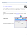
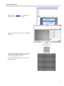
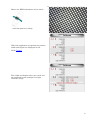
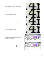
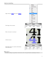
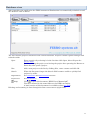
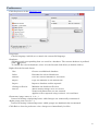
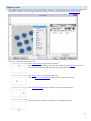
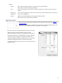
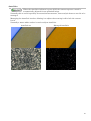
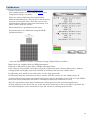
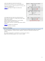
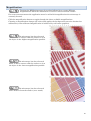
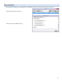
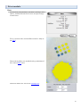
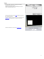
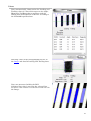
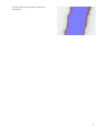
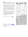
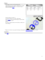
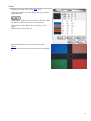
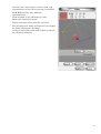
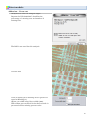
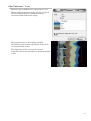
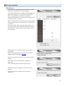
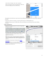
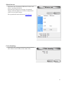
DIGITAL Pocket
Microscope
User’s manual
Version 2
2
Contents
Overview
5
Getting started
6
Installation
6
Activation
6
Create a new project
7
First calibration
9
Measure something
11
Analyze something
13
What now?
13
Database view
14
Preferences
15
Project view
16
Image
17
Zoom
17
Pan
17
Image context menu 17
ROI
18
Capture
19
Capture list
19
Operator panel
20
Settings list
21
Threshold setting
21
Tags
22
Camera Resolution
22
AutoGain
23
Calibration
24
Camera Settings
25
Magnification
26
Deactivation
27
Measure
28
Measure objects
28
Measure list
28
ROI
28
Distance
28
Angle
29
Circle
29
Area
29
Step distance
29
Print module
30
Dots
30
Voids
31
Lines
32
Mottling
34
Shapes
35
Satellites
35
Missing dots
36
Color
37
Fusing cracks
39
Color mottle
39
Paint module
40
Adhesion - Cross-cut
40
Film Thickness – V-cut
41
Hardness - Buchholz Indentation
42
Impact – Flexibility
Hardness - DUR-O-Test
Color
Color mottle
Textile module
Cleanliness
Stain spreading
Stain saturation
Abrasion test
Color bleeding
Color
Color mottle
Keyboard
Accessories
Metal Holder
Extension Tube
43
43
43
43
44
44
45
46
47
47
48
48
49
50
50
50
3
Overview
The DPM instruments deliver crisp, clear color images with a resolution up to
1280x1024 pixels. The integrated LED illumination can be switched on/off, which
allows optional external illumination for special investigations. The touch button on
the DPM is pressed to capture an image. With the DPM placed directly upon a
surface, the focus wheel has two positions giving different magnification levels. The
DPM can also be placed on a distance above the test surface and will then view a
larger area.
The DPM application features dimension calibration, background correction and
image enhancements. Captured images are stored in a database together with
comments, manual measurements (distance, area, angle and radius) and automatic
analysis results. Live images may be continually analyzed to provide instant results.
All may be exported/imported and printed as reports. Different modules are used to
group functionality. Currently there are three modules, Print, Paint and Textile.
All modules are available for evaluation for 30 days after installation.
This documentation best viewed electronically due to link references.
Links are underscored.
References to named interface items are italic.
Length/area units are millimeters (mm) unless otherwise noted.
5
Getting started
Quick start checklist
Installation
The DPM application runs under Windows operating systems XP/Vista/W7 and W8 (32/64 bit).
The latest version of the application and this manual may be accessed from
http://www.fibro.se/dpmfiles/dpm.htm
Insert the DPM CD or launch the downloaded executable and follow the installation instructions.
After installation connect the DPM microscope to a USB port, allow time for the OS to assign
drivers.
Activation
To use the DPM software beyond the demo period it needs to be activated using a user id and
password.
Only a set number of activations are possible (default two) on different PCs.
If moving the software to another PC, first perform a Deactivation on the previous PC to regain
its activation.
The activation is automatic if your computer has an internet connection.
Launch the DPM application.
Click Registration
Enter your User ID and Password and click
Login.
6
Enter contact details to receive information
about future software upgrades and user’s
manuals.
Click Activate DPM Software (bottom of
page).
If the automatic software activation fails, a manual activation window is presented.
Send us your Activation Code number (email
[email protected] or fax +46 8 775 00 91).
We will respond promptly during business
hours (UTC+01 time zone) with a code.
Enter the code in the field and press
Activate.
Create a new project
Click New
Enter a name and click Ok.
7
The application automatically selects and
opens the “Test” project.
8
First calibration
Right click the Image area to bring up a
context menu, choose Calibrate
The area to the right now has a Calibrate
heading
Use the DPM Calibration Sheet supplied
with the instrument and place the
microscope against pattern a.
If using DPM 300 please do not use the
protective cap.
9
Rotate the DPM instruments focus wheel…
…until the pattern is sharp
When the application recognizes the pattern,
width and height are displayed in red.
Click Capture
The width and height values are saved and
the application now prompts for a light
reference image.
10
Without changing the focus wheel, move the
DPM instrument to the White Reference
Sheet supplied with the instrument.
Then click Capture
Calibration done, click Exit
Measure something
Move the DPM instrument to something
interesting.
Click the Distance tool
11
Move the mouse cursor to a starting point.
Click the right mouse button.
Move the mouse cursor to an ending point.
Click the right mouse button.
The Measure list now contains an entry for
the line and it’s length
To stop measuring lines click
12
Analyze something
Right click the Image and choose Shapes.
The Shapes list is shown
Move the mouse to an object.
Click the object
The Shapes list now contains information
about the object.
What now?
Continue reading or experiment and return to the user’s guide when something is unclear.
13
Database view
After launching the application the DPM instrument illumination is automatically switched on and
the database view is shown.
The list contains projects contained in the current database. Projects contain captured images and
related results.
Open
Enter a project by selecting it in the list then click Open, this will open the
Project view.
Double-clicking the project or selecting the project then pressing the Return or
Enter key also opens a project.
New
Add a new project to the list by clicking New, enter a name and click Ok.
Search
When the list grows larger the Search field becomes useful to quickly find
projects by name.
Registration
See Activation and Deactivation sections.
Preferences
See Preferences.
(help)
Click
to open this document “DPM User's Manual.pdf”
The file is located in the same folder as the DPM executable.
A html version of this document is available online (see link)
Deleting and renaming is done through the lists connect menu (right click).
14
Preferences
Click Preferences in the Database view.
Languages
Choose language, initially set to match the current OS language.
Databases
All images and corresponding data are saved in a database. The current database is prefixed
with a (square).
To change the current database, select it in the list and click Select (or double-click it).
Right-click the list and choose:
New
Creates an additional database.
Delete
Discards the selected databases.
Rename
Give the selected database a new name.
Export
Copy the database to an external file.
Import
Import a database earlier exported.
Garbage collection
Minimize the database file sizes.
Recover
Allows deleted images to be recovered.
Names and dimensions are not restored.
Applies to files captured using version 2.1.3.0 and later.
Enumerate image names (1, 2, 3…)
Instead of having a timestamp name, added images are numerically enumerated.
Alpha group names (A, B, C…)
Instead of having a timestamp name, added groups are alphabetically enumerated.
Click Exit to close the preference view, changes are immediately in effect.
15
Project view
The DPM software is based on a genuine database structure, which keeps track of all captured
images The Project view will appear when a Project has been opened from the Database view.
The view is divided into four parts.
The Capture list lists previous captures.
Selecting a capture miniature loads the original in the Image area below
where measurements and analysis may be performed.
The Image, live or previously captured.
Use the Image context menu (right-click) to choose function.
The Operator panel shows results and accepts parameters.
The bottom part contains a collection of settings/controls.
16
Tags, Textual comments.
Capture, captures an image or resumes live image after viewing a captured image.
Close, closes this project and returns to the Database view
Resolution, change the camera resolution
Zoom, view the Image scaled to fit or at a specific percentage
LED toggle illumination on/off.
Magnification, inform the application which magnification the DPM instrument is
set to.
AutoGain, toggles auto gain on/off.
Image
The image area is either showing a live instrument view or a previously
captured static image. A green border around the Capture button indicates
a live image.
Rulers top/left show the dimensions of the viewed area, to change
dimensions click the Magnification button.
Zoom
Zoom the image by choosing a percentage in the Zoom popup list.
Or by moving the mouse over the image and turning the mouse scroll wheel.
Pan
Pan the image by using the bottom/right scroll bars or drag the image while holding down the
space bar key.
Image context menu
Right-click the image to access the images context menu.
Much of the DPMs functionality is accessed from this menu.
The top section holds general functionality, the center part lists the module functions and the
bottom part has printing and export functions.
17
Change modules in the module submenu.
Print and Print preview is available when viewing captured images.
Use Print preview to select the printer and preview and print.
Use Print to directly send the report to the printer.
The printed output contains the current view of the image and the results of the current
function.
Export may be done at any time even while looking at a live image.
Image
Allows the current raw image to be saved to a file (bmp or jpg).
View
Allows the current image as currently viewed to be saved to a file (bmp or
jpg).
Clipboard
Places the current image as currently viewed in the clipboard as a
metafile.
Results to
clipboard
Places the selected functions current results in the clipboard as text.
ROI
The ROI (Region of interest) is a border enclosed rectangle superimposed on the image.
The ROI is used to limit an analysis to its area instead of the full image area.
The ROI is resized by adjusting its borders and moved by dragging it around by its center.
Move it off the image to have it enclose the full image.
Create a new ROI by drawing outside the current (or inside a fully enclosed) ROI.
To draw, click and hold the right mouse button while dragging the mouse in some direction.
The ROI s current width, height and area are constantly displayed at the top of the Measure
panel.
The border color of the ROI is set in the Measure panel.
18
Capture
There are three ways to capture an image.
Click Capture.
Touch the capture button on the DPM instrument.
Press F4 on the keyboard.
When viewing a live image the Capture button border is green.
When viewing a previously captured image the Capture button border is grey, to resume viewing
live images press the Capture button.
The Capture buttons context menu (right-click) reveals more options.
One click
When checked the application does not stop to view a captured image.
When unchecked the application stops to view the captured image, to
resume viewing the live image click Capture again.
Sound
When checked a camera click sound is made each time an image is
captured.
Capture list
Captured images are added to the Capture list.
Click on a capture to view it in the image area.
Hover the mouse over the image label to see capture date and time.
Enter/exit a folder by double-clicking it.
The Capture list has its own context menu (right click).
Group
The selected images are grouped into a folder, only one level of folders may
exist.
Images may also be dragged into an existing folder.
Ungroup
The selected images are removed from their current folder group.
Images may also be out of the folder.
Delete
Delete the currently selected images/folders. May also be done with the Delete
key.
Rename
Rename the currently selected image/folder. May also be done by doubleclicking the image label.
Image
dimensions
Allows the dimensions of the currently selected images to be redefined.
Enter width or height of the image.
If the image contains a known width or height, use the ROI to mark it and
check Specify ROI dimensions then enter width or height.
Image
overview
Toggles full window view of Capture list.
19
Export
Image
The selected images will be copied to the specified folder.
May also be done with drag and drop.
View
The current image view for the selected images are copied to the specified
folder.
Results to
clipboard
The selected images results for the currently selected function are copied as
text to the clipboard.
Import
Allows external bitmaps to be imported into the list.
May also be done with drag and drop.
Operator panel
The contents of this panel depend on the function selected in the Image
context menu.
Calibrate and Camera settings have panels for general settings while the
Measure and analysis panels are specific to the image.
The top title button specifies which function is active.
Image specific panels normally show results.
On a live image, results are constantly recalculated.
Functions that have a Reload/Save buttons initially
use the current settings to calculate results. On
captured images specific settings may be saved and
reloaded (using the Reload and Save buttons).
A captured image can only have one saved result per
analysis type.
20
Settings list
Clicking the title button opens a settings list
specific for the current function.
Select a list item and its currently used settings
are shown under the list.
Changes to settings are performed immediately.
Click Save settings to change the default settings,
click Defaults to revert to factory defaults.
Threshold setting
Many functions use some form of Threshold.
A threshold is used to create a selection of image pixels.
The threshold Mode defines how threshold is performed and which parameters may be
changed.
Reset reverts the Mode to its defaults.
Thresholds operate within the current ROI and uses the ROIs color to mark the current
selection.
While editing a threshold the normal image control interface may be limited in favor to allow
a pipette to sample image data.
The threshold control ranges from zero at the bottom (darkest) and 255 at the top
(brightest).
The range between the left/right arrows represent the selection. The darker band
is excluded from the selection.
The threshold values may be directly entered in the edit fields or modified by
dragging the arrows.
The center diamond drags both arrays.
Click on an arrow to select it, a selected arrow allows sampling input from the
image using the pipette .
Checking Inv reverses the selection range.
Grayscale
The selection is based on a grayscale representation of the image.
Gray median
The threshold is set at the median of the ROIs grayscale histogram.
The darker half is used for the selection.
Red/Green/Blue
The selection is based on a single color channel.
21
Percent
The threshold is set to select a percentage of the area using a
grayscale histogram.
The darker part is used for the selection.
Color
The selection is based on a HSB (hue, saturation, brightness) color
version of the image.
With this threshold the pipette
gradually adds samples that are to
be included in the selection.
Undo a pipette sample with ctrl-z, click Reset to deselect all.
Click Save to save the threshold for later use.
Use the dropdown list to recall previously saved threshold.
Right-click the dropdown list and select Delete to remove a previously
saved threshold.
Auto
Is a general threshold that works for most cases.
Tags
Tags are small notes used to point out certain features in an image.
The tags are superimposed and will not affect the image in any way.
To create a new Tag, click on the Tag icon below the Image Area.
Then position the cursor in the image at the point of interest and click on the left mouse button.
Enter the text and left-click outside the Tag to exit.
To move an existing Tag, position the cursor inside the Tag and press the left mouse button.
Drag the Tag to a new position and release the mouse button when Tag is in its correct position.
To edit a Tag or change its size, left-click inside the Tag
To remove a Tag, right-click it and select Delete.
Camera Resolution
The DPM application will start at a resolution of 640x480 pixels by default.
This resolution offers a good image quality and the captured images will still not become too big.
Select a higher resolution only when a higher image quality is required (image update speed may
suffer).
To change the camera resolution, select a new resolution in the drop-down list at the bottom of
the window. The LED light source is switched momentarily off and on when switching to a new
resolution.
22
AutoGain
When the AutoGain indicator is green (ON) the camera exposure control is
automatically adjusted for an optimized image.
Normally this is useful especially for manual measurements, some analysis however need it to be
managed.
Managing the AutoGain involves allowing it to adjust then turning it off to lock the current
levels.
Normally a matte white surface is used to adjust AutoGain.
AutoGain on
Managed AutoGain
23
Calibration
Choose Calibrate in the Image context menu.
The Calibrate panel is shown and the Image may
temporarily change resolution.
There are three calibration slots representing
different magnifications. The top slot is when using a
stand or an extension tube. The other two are the
magnifications obtained when the instrument is in
direct contact with the surface.
Each calibration is performed in two steps.
First dimensions are calibrated using the DPM
Calibration Sheet…
…then the illumination variance is calibrated using a White Reference Sheet.
Both sheets are supplied with the DPM instrument.
Dimension calibration is done with a DPM Calibration Sheet.
If the sheet is not available, click Open.pdf in the Calibration panel. Print without color, without
scaling (width and height of pattern a should be 25.4mm) and avoid the “Moiré effect”.
If calibrating on a stand or extension tube, use the large pattern b.
If calibrating with the instrument in direct contact with the surface use the small pattern a.
At times when using a stand an external light source may be preferable to the built in. If the LED is
turned off during calibration this will be remembered when the calibration is used.
Turn the instruments focus wheel and obtain a sharp pattern at the desired magnification.
To help with this is the Focus bar, try to get the green center bar as far to the right as possible, the
red surrounding bar is the current best, reset the red bar by clicking the Focus bar.
24
When the application detects the pattern its
dimensions are proposed at the corresponding slot.
It is not necessary to align the pattern in any way, the
application will detect it.
Capture the image to complete the dimension
calibration.
The application now expects the White Reference
Sheet (if not available use a high quality white matte
photo paper instead).
Without adjusting magnification, view the White
Reference Sheet with the instrument.
When using a stand use a uniform white matte surface
instead.
Capture to complete the calibration.
To abort calibration click Exit.
Camera Settings
The camera inside the DPM instrument is controlled from the DPM software where the camera
settings of Brightness, Contrast, Gamma, Exposure, Sharpness, Saturation and Hue can be
adjusted.
The Profiles popup allows a predefined set of settings to be chosen.
Right-click the Profiles popup to save or delete a profile.
25
Magnification
Turning the DPM microscopes focus wheel allows focus on two different
magnifications while the instrument is in direct contact with the surface.
For correct measurements the application must be told which magnification the microscope is
currently focused.
Click the magnification button to toggle through the three available magnifications.
Choosing a magnification changes the rulers and applies the background correction obtained at
calibration (a non-calibrated magnification is indicated by red button graphics).
The microscope has been focused
while in direct contact with the surface to view
the object in the highest magnification possible.
The microscope has been focused
while in direct contact with the surface to view
the object in the lowest magnification possible.
The microscope has been focused
some distance from the surface (on a stand).
26
Deactivation
To activate the software on another PC it will first need to be deactivated on the current PC.
Click the Registration button
Click Deactivate DPM Software.
27
Measure
Measure is used to perform manual measurements, it’s the default DPM function chosen from the
top of the Image context menu the only function not part of a module.
The Measure panel has a number of tools and a set
number of colors.
To measure select a tool and optionally a color,
perform the measurement and select (ROI) when
done.
Measure objects
Measure objects are superimposed graphics on the Image.
Hovering the mouse over an object exposes its control points.
Grabbing an object body allows it to be moved.
Control points can be moved, some tools allow points to be removed as well
(Delete key)
Measure list
Measure results are added to the Measure list.
Selecting a result highlights its object in the Image.
To delete results select them in the list and press the
delete key.
Choosing a color while the list has a selection
changes the results to that color.
The list is automatically saved with its captured
image.
ROI
Deselects the current tool and reverts the default ROI control.
Selecting a color changes the ROIs color for all functions.
Distance
Measure the distance between two points.
Click the distance tool
On the Image, click the first point then click the second point alternatively
click and hold then drag to the second point.
A line is drawn between the two points and an entry is made in the Measure
list.
Select
when done.
28
Angle
Measure an angle in degrees.
Click the angle tool.
As with the Distance tool click the first point then click the second point
alternatively click and hold then drag to the second point.
Click a third point to add the angle.
Select
when done.
Circle
Measure circumference, radius and area of a circle.
There are two ways to specify a circle.
Click the circle tool.
Click and hold while dragging away from the circle center.
Click three points, a circle intersecting all points is added.
Select
when done.
Area
Measure the perimeter and area of an irregular shape
Click the area tool.
Click at least three points then to complete the area right-click the mouse.
Click and hold to freehand draw.
An area will not be calculated if the border intersects itself.
Select
when done.
Step distance
Measure the distance of an irregular border.
Click at least two points then to complete the path right-click the mouse.
Click and hold to freehand draw.
Select
when done.
29
Print module
Dots
Counts dots and satellites, measures average area
(mm²), standard deviation of area and percentage
of total area.
To be counted, dots and satellites must be fully in
the ROI.
Dots and satellites are marked using variations of
the current ROI color.
Detection limits are set in the Settings list.
30
Voids
Counts voids, measures average area (mm²),
standard deviation of area.
Voids are detected when a solid black area has
white, unprinted spots in it
Voids are measured in the ROI which is inverted
for viewing reasons.
Dots are marked using variations of the ROI color.
AutoGain management is needed to measure
Voids.
Detection limits are set in the Settings list.
31
Lines
Lines automatically characterize the Leading and
Trailing edges of a line with respect to its Angle,
Blurriness and Raggedness together with the
Width (mm) and Contrast of the line according to
the ISO13660 specifications.
Selecting a line in the list highlights the line in
the Image and details Leading and Trailing data.
Lines are measured within the ROI.
A lighter blue color is used for the selected line.
To select a line choose it in the list or click on it in
the Image.
32
A closer look reveals points used in the
calculation.
33
Mottling
Mottling and Graininess characterize how evenly
a uniformly printed area appears to the human
eye.
For Graininess the high frequency variations are
characterized from sub-images (tiles) of different
sizes from 0.042 mm (0.0018 mm²) up to 1.02 mm
where the smaller tiles will divide the defined
region into more sub-images (Count). The
variation between the sub-images of a particular
grid size is then calculated as the standard
deviation (S.D). Finally the different standard
deviations are averaged into one single Graininess
number.
Mottling describes the low frequency pattern
using a single Grid size of 1.27 mm. According to
ISO 13660 the region must be at least 161 mm²
(12.7 x 12.7mm) in which case the DPM
instrument should be used with the DPM
Extension Tube (see 10) or installed on a stand
(see 5.3) to obtain 10x10 for mottling
measurements.
Mottling is performed in the current ROI.
Pixel align option is found in the Settings list.
When checked, the grid tile size is aligned to the
closest pixel.
When unchecked grid tile size is preserved using
pixel fractions.
34
Shapes
The Shape function will automatically
characterize the area (mm²), widths (mm), height
(mm) and perimeter (mm) of a selected object
inside the defined ROI.
Click an object to select it.
A selection point is set at the click point.
If the Image is Live and the shape is removed the
selection point is lost.
Select
To select a shape choose it in the list or click on it
in the Image.
Shapes do not have any special settings although the Threshold setting may be useful.
Satellites
See Dots.
35
Missing dots
Determines the number of missing dots in a
regular printed pattern.
The Missing dots function detects the dominating
dot pattern in an image and determines the
average dot size and the dot grid parameters.
Based on this, a grid of “perfect” dot circles
(expected dots) are placed across the image.
Finally each expected dot circle is matched to the
printed dot appearing in each such position. If the
printed dot does not cover a defined area of the
expected dot circle, it is defined as missing.
Missing area operates in the current ROI.
Actual missing dots are marked red.
A close look reveals the area inside the expected
dot.
A red circled dot indicates missing.
Limits are set in the Settings list.
A dot is marked missing if its area is less than
Missing (%).
A dot is registered (not marked) as large if area
around is greater than Large (%) of the dot size.
36
Color
Displays average color in the ROI area.
Color only works correctly when using the correct
magnification.
Click Add to add the current color to the list. Move
the ROI to another location to add another.
Select and use the Delete key to remove a list
entry.
Click Clear to clear the list.
Each ROI added to the list is marked in the
Image.
Click on a list item or an image mark to highlight
it.
37
Clicking Color View replaces the list with a 3D
representation of the colors currently in the ROI.
RGB, HSB and Lab have different
representations.
Click and hold in the 3D image to rotate.
Right-click and hold to zoom.
The Reset button resets rotation and zoom.
The 3D image and Image locations may be toggled
by double-clicking the 3D image.
Uncheck Auto update and click Update to refresh
the 3D image manually.
38
Fusing cracks
Use Fusing cracks to determine the magnitude
toner loss in a fold.
AutoGain management is needed to measure
Fusing cracks.
Density is the area of cracks per mm along the
fold.
The perpendicular width contains 1 standard
deviation of cracks along the fold
The direction angle is determined and S.D.
Color mottle
See Mottling.
Mottling is calculated using the grayscale brightness difference of image pixels.
Color mottling is calculated using color point distances in a 3D RGB color cube.
The cube is dimensioned so that the grayscale running between the black and white corners of
the cube is the same as for grayscale mottling.
39
Paint module
Adhesion - Cross-cut
Analysis of a cross cut using six edges.
Reports the ISO 2409:2007 classification,
percentage of missing area and number of
missing tiles.
The ROI is not used for this analysis.
A closer look
A tile is missing if its missing area is greater or
equal to Missing (%).
Adjust cut width using Grove width (mm) .
When Show percent detail is checked each tile is
presented with a missing percent value.
40
Film Thickness – V-cut
Measures layer thickness as exposed by a V-cut.
Where Angle is the blade angle, the layer color in
Position and Thickness calculated from the
measured width and known angle.
The measurement is done inside the ROI.
The ROI may need some adjustment if the cut is
not automatically found.
The alignment of the cut must be viewed
vertically and the measurement is performed right
to left.
41
Hardness - Buchholz Indentation
Locates and measures the indentation length of a
Buchholtz indentation.
The closest indentation length in the list is
marked for related information.
The indentation is marked in the Image.
42
Impact – Flexibility
Calculates the spherical length after a flexibility
test as well as the number of average “rings from
the center.
The image must be centered on the Center circle.
The calculations occur within the ROI, excluding
the yellow Center circle area.
The Center circle size may be changed in the
Setting list.
Hardness - DUR-O-Test
Is functionally equivalent to Fusing cracks.
Color
Same as Print Color.
Color mottle
Same as Print Color mottle
43
Textile module
Cleanliness
Calculates the brightness/color difference before
and after a specimen has been washed.
A measurement may be continued, allowing before
and after captures to be performed separately.
The average difference between the before
captures (compared to each other) are presented in
the Before diff. % column.
The average difference between the average before
an the current after is presented in the After diff.
% column.
For best results make sure that the images are
captured in the same lighting conditions and that
the material is placed on the same surface (if it’s
see-through).
The first step is to fix the camera to a known
sensitivity.
This is done by placing the camera on a white
surface and performing a Capture.
The second step is to capture one or more before
images.
Press Done when all the before images are
captured.
Note: Pressing Previous back up one step.
The third step is to capture one or more after
images.
Press Finish when all the after images are
captured.
44
Note that the measurement may be continued at
any time.
The first step (white surface) is always performed
when continuing.
Delete unwanted captures by selecting them in the list and pressing the Delete key (first capture
cannot be deleted in this version).
Stain spreading
Measures the progression of a stain as it spreads
outward.
The chart shows area difference over time.
The difference is compared to the Reference
image.
Please note that this measurement is very light
variation sensitive.
For best results avoid environments where light
changes (sunlight/moving objects casting shadows
etc).
Fix the camera on the textile and turn off
AutoGain.
Prepare a small stain drop.
Press Start to start the measurement and place
the drop on the textile.
45
Wait until all images have been captured.
Select all images between the Reference and the
first stain image press the Delete key.
To exclude the initial stain area from the spreading area, select the first stain image and click
Exclude.
Change the reference image by selecting and image and clicking Reference.
Additional images may be added after the measurement by increasing Count and clicking
Continue.
Stain saturation
Measures the progression of a stain as it spreads
through a textile.
To perform this measurement the camera is facing
upwards towards the textile and the stain is
applied from the top.
Make sure to have a protective glass between the
camera and the specimen (tilted to avoid glare) to
avoid the possibility of the stain dropping into the
camera.
Currently the interface is identical to Stain
spreading.
The only difference being that Reference should be
moved to the first non-saturated image and
Exclude serves little use.
46
Abrasion test
Calculates the Graininess difference before and
after a specimen abrasion.
Presents the Graininess average of captured
images and the Difference of the average before
value for each after image.
For operational instructions see Cleanliness.
Color bleeding
Calculates the average transition width between
two colors or two shades of the same color.
47
The calculations occur within the ROI.
Color
Same as Print Color.
Color mottle
Same as Print Color mottle
48
Keyboard
F4
Capture
F6
Toggle Capture list and Operator panel
Shift F6
Toggle Capture list
Ctrl F6
Toggle Operator panel
F11
Full screen
Space
Pan in Image
49
Accessories
Accessories are available from the DPM distributer.
Metal Holder
This removable metal holder is suitable for
measurements in direct contact with a flat or
slightly curved surface as the weight keeps the
microscope standing upright. It prevents stray light
from entering the test area and the front has a
protective PTFE gasket to prevent the test surface
from being scratched.
Part 68-86-01
Extension Tube
Use when viewing larger surfaces isolated from
external light.
Satisfies the ISO 13660 mottle requirement of at
least 161 mm² measuring area.
Part 68-86-18
50