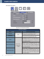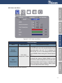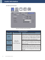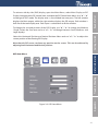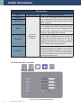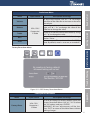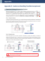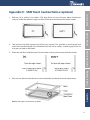
1
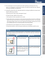
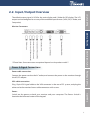
Industrial LCD Monitor User Guide (with G2A LCD Control Board) Version 12 The specification is subject to change without notice. Manufacturer assumes no responsibility for Error Contained. Part No.91521112100F Jim Lin Nov 12, 2004 Initial draft. Peter Nov 18,2004 Update supported mode Updated OSD Keys and Menus Nelson Oct 26, 2005 Updated OSD keys and menus Nelson Feb 07, 2006 Added RS232 command code Nelson Mar 07, 2006 Added hot key flipping image function Nelson May 21, 2006 Added outline drawing and remote control description Nelson July 17, 2006 Added scaling hot key function Nelson Aug 23, 2006 Changed remote control Brian Dec 18,2008 Gamma change 1.8 ,2.2 RS232 command code change Brian Jun 26, 2009 Modify the PIP description Winnie Jan,2014 Getting Started Description Useful Information Date Trouble Shooting Author Modify typesetting and OSD content Appendix Revision Read Me First Revision History 1 Contents Contents Chapter 1: Read Me First . . . . . . . . . . . . . . . . . . . . . . . . . . . . . . . . . . . . . . . . . . . . . . . 3 Important Safety Instructions . . . . . . . . . . . . . . . . . . . . . . . . . . . . . . . . . . . . . . . . . . . . . . . . . . . . . . . . . . . . 4 Chapter 2: Getting Started . . . . . . . . . . . . . . . . . . . . . . . . . . . . . . . . . . . . . . . . . . . . . 7 2-1. Introduction . . . . . . . . . . . . . . . . . . . . . . . . . . . . . . . . . . . . . . . . . . . . . . . . . . . . . . . . . . . . . . . . . . . . . . . . . 8 2-2. Input /Output Overview . . . . . . . . . . . . . . . . . . . . . . . . . . . . . . . . . . . . . . . . . . . . . . . . . . . . . . . . . . . . . 9 2-3. Remote Controller . . . . . . . . . . . . . . . . . . . . . . . . . . . . . . . . . . . . . . . . . . . . . . . . . . . . . . . . . . . . . . . . . 11 2-4. G2A Kit Memo (Optional for 24V input DC solution) . . . . . . . . . . . . . . . . . . . . . . . . . . . . . . . . . 12 CHAPTER 3: Useful Information . . . . . . . . . . . . . . . . . . . . . . . . . . . . . . . . . . . . . . . . 13 3-1. Using the LCD Monitor . . . . . . . . . . . . . . . . . . . . . . . . . . . . . . . . . . . . . . . . . . . . . . . . . . . . . . . . . . . . . 14 3-2. Cleaning the Monitor . . . . . . . . . . . . . . . . . . . . . . . . . . . . . . . . . . . . . . . . . . . . . . . . . . . . . . . . . . . . . . 28 3-3. Disclaimer . . . . . . . . . . . . . . . . . . . . . . . . . . . . . . . . . . . . . . . . . . . . . . . . . . . . . . . . . . . . . . . . . . . . . . . . . 28 CHAPTER 4: Trouble Shooting . . . . . . . . . . . . . . . . . . . . . . . . . . . . . . . . . . . . . . . . . 29 4-1. Trouble Shooting . . . . . . . . . . . . . . . . . . . . . . . . . . . . . . . . . . . . . . . . . . . . . . . . . . . . . . . . . . . . . . . . . . 30 Appendix . . . . . . . . . . . . . . . . . . . . . . . . . . . . . . . . . . . . . . . . . . . . . . . . . . . . . . . . . . . . 31 Appendix A: Supported Modes . . . . . . . . . . . . . . . . . . . . . . . . . . . . . . . . . . . . . . . . . . . . . . . . . . . . . . . . . 32 Appendix B: Using RS-232 Command Code to set system (Optional) . . . . . . . . . . . . . . . . . . . . . 34 Appendix C : Using RS-232 Command Code to check system status (optional) . . . . . . . . . . . 36 Appendix D : Caution on Handling Transflective (optional) . . . . . . . . . . . . . . . . . . . . . . . . . . . . . . 38 Appendix E : SAW Touch Caution Notice (optional) . . . . . . . . . . . . . . . . . . . . . . . . . . . . . . . . . . . . . . 39 2 www.winmate.com.tw Read Me First 1 Getting Started CHAPTER Read Me First The specification is subject to change without notice. Appendix Trouble Shooting Useful Information Manufacturer assumes no responsibility for Error contained . 3 Read Me First IMPORTANT SAFETY INSTRUCTIONS 1. Please read these instructions carefully before using the product and save for later reference. 2. Follow all warnings and instructions marked on the product. 3. Unplug this product from the wall outlet before cleaning. Clean the product with a damp soft cloth. Do not use liquid or aerosol cleaners as it may cause permanent damage to the screen. 4. Do not use this product near water. 5. Do not place this product on an unstable cart, stand, or table. The product may fall, causing serious damage to the product. 6. Slots and openings in the cabinet and the back or bottom are provided for ventilation; to ensure reliable operation of the product and to protect it from overheating, these openings must not be blocked or covered. The openings should never be placed near or over a radiator or heat register, or in a built-in installation unless proper ventilation is provided. 7. This product should be operated from the type of power indicated on the marking label. If you are not sure of the type of power available, consult your dealer or local power company. 8. This product is equipped with a 3-wire grounding type plug, a plug having a third (grounding) pin. This plug will only fit into a grounding-type power outlet. This is a safety feature. If you are unable to insert the plug into the outlet, contact your electrician to replace your obsolete outlet. Do not defeat the purpose of the grounding-type plug. 9. Do not allow anything to rest on the power cord. Do not locate this product where persons will walk on the cord. 10. If an extension cord is used with this product, make sure that the total of the ampere ratings on the products plugged into the extension cord does not exceed the extension cord ampere rating. Also make sure that the total of all products plugged into the wall outlet does not exceed 15 amps. 11. Never push objects of any kind into this product through cabinet slots as they may touch dangerous voltage points or short out parts that could result in a risk of fire or electric shock. Never spill liquid of any kind on the product. 4 www.winmate.com.tw Read Me First 12. Do not attempt to service this product yourself, as opening or removing covers may expose you to dangerous voltage points or other risks and will void the warranty. Refer all servicing to qualified service personnel. 13. Unplug this product from the wall outlet and refer servicing to qualified service personnel under the following conditions: a. When the power cord or plug is damaged or frayed. Getting Started b. If liquid has been spilled into the product. c. If the product has been exposed to rain or water. d. If the product does not operate normally when the operating instructions are followed. Adjust only those controls that are covered by the operating instructions since improper adjustment of other controls may result in damage and will often require extensive work by a qualified technician to restore the product to normal operation. Useful Information e. If the product has been dropped or the cabinet has been damaged. f. If the product exhibits a distinct change in performance, indicating a need for service. CAUTION Read manual prior to installing the product. The operation of products depends on you reading and following the information in this manual. Re-check your work prior to operating the product. PREVENTION Trouble Shooting EFFECT Sunlight shines directly will You should avoid placing the cause the panel damage. product under direct sunlight. If the product is close to the You should avoid placing the wet ground such as grassplot, product in wet environment. the moisture between panel and glass will make the product malfunction. Appendix EVENT 5 Getting Started 6 www.winmate.com.tw Read Me First 2 Getting Started CHAPTER Getting Started Thi s chapter tells you will find instructions for the Useful Information following procedures: Appendix Trouble Shooting •Introduction • Input /Output Overview • Remote Controller • G2A Kit Memo (Optional for 24V input DC solution) 7 Getting Started 2-1. Introduction About the Product This product is a high quality TFT LCD panel. It is designed to meet the demanding performance requirements of today’s business and industrial applications. Notice 1. Do not touch the LCD panel surface with sharp or hard objects. 2. Do not use abrasive cleaners, waxes or solvents for cleaning, use only a dry or damp, soft cloth. 3. Use only with a high quality, safety-approved, AC/DC power adapter. Check List Before using this monitor, please make sure that all the items listed below are present in your package 1. VGA cable x1 2. AC to DC adapter x1 3. Power cable x1 4. User manual x1 5. DVI cable (optional) x1 6. Audio cable (optional) x1 7. 24V to 12V transfer board(Optional) X1 If any items are missing or damaged, please contact your dealer immediately. 8 www.winmate.com.tw Read Me First 2-2. Input /Output Overview The default output signal is VGA for the main display and S-Video for PIP display. The LCD output can be configured to use any of the available input formats (VGA, DVI, S-Video, and Composite). Useful Information Getting Started Monitor Connectors **Please Note: Some connectors are optional depends on the product model** Trouble Shooting Power & Signal Connections Power cable connection: Connect the power cord to the AC outlet, and connect the power to the monitor through the AC/DC adapter. VGA cable connection: Plug 15-pin VGA signal cable to the VGA connector in the rear of PC system, and plug the other end to the monitor.Secure cable connectors with screws. Appendix Power: Switch on the power on both your monitor and your computer. The Power Switch is located at the leftmost button of the keypad. 9 Getting Started Optional Cable Connections The LCD monitor is designed to work with a variety of compatible video sources. Due to the possible deviations between these video sources, you may have to make adjustments to the monitor settings from the OSD menu when switching between these sources. DVI cable connection (Optional): Plug the DVI signal cable to the DVI connector in the rear of the PC system, and plug the other end to the monitor. Secure cable connectors with screws. RS232 cable connection (Optional): You will be able to develop your own application software utilizing the built-in RS232 command code. The application software can send command from PC to LCD monitor via RS232 port to control LCD monitor. Please refer to Appendix B for built-in RS232 command code. Component Board and Cable connection (Optional): Plug the Component signal cable into J19 connector on G2A board and COMP100. 10 www.winmate.com.tw Read Me First 2-3. Remote Controller Install Battery in the Remote Controller Insert two AAA alkaline batteries and match the (+) and (-) on battery to the marks inside the battery compartment. Service life of battery: Getting Started 1. The battery normally last for about one year although this depends on how often and for what operations the remote control is used. 2. If the remote control unit fails to work even then it’s operated near the player, please replace the battery. Description Power Power on/off AUTO Auto Auto Adjust SOURCE Source Switch input source SWAP Swap Swap images in PIP/PAP mode MENU Menu Display OSD menu / Volume Adjust volume PIP PIP Perform PIP mode FLIP Flip Flip image EXIT Exit Return to the previous menu level RESET Reset Factory reset SCALING Scaling Change the scaling mode to 1:1, Fill or aspect A-COLOR Auto-color perform Auto-Color Balance Mute Mute Select Navigating to Up/Down/Left/Right Enter Execute C1 C1 (optional) Switch to Component 1 mode C2 C2 (optional) Switch to Component 2 mode CVBS CVBS (optional) Switch to CVBS mode VGA VGA (optional) Switch to VGA mode MUTE / / ENTER Trouble Shooting Function Appendix Key Useful Information Remote Control Key Definitions 11 Getting Started 2-4 G2A Kit Memo (Optional for 24V input DC solution) Warning: 1. See the instruction if the DC adapter is 12V or 24V. If the DC adapter is 24V DC, need to come with “24V to 12V power transfer board”. 2. 24V to 12V Power transfer board installation guide: BEFORE connecting power cord to AC outlet, please ensure ADAPTER CABLE, POWER CABLE to AD BOARD and INVERTER CABLE have been connected. This action prevents volt converter board (GAP-P0420) from noise issue. This issue does not influence any function. 12 www.winmate.com.tw Read Me First 3 Getting Started CHAPTER Useful Information Useful Information When using a device, be sure to read the instructions accompanying the device together with the relevant section in this chapter. This chapter gives guidelines on using these devices: • Using the LCD Monitor • Cleaning the Monitor Appendix Trouble Shooting •Disclaimer 13 Useful Information 3-1. Using the LCD Monitor OSD Key Definition Type A. Type B. POWER Initiates power-up sequence from low power mode or enters low lower mode from normal operation. UP Selects the previous item in the Item Menu. DOWN Selects the next item in the Item Menu. ENTER/MENU i. When OSD is disabled, it displays the OSD Main Menu. ii. When OSD is enabled, it confirms a selection. 14 www.winmate.com.tw Read Me First LEFT Moves left when navigating the Main Menu and Sub Menu. It also decrements a slider bar. SOURCE RIGHT i. When OSD is disabled, it cycles through the available input sources for the Main Display. AUTO Getting Started ii. When OSD is enabled, it moves right when navigating the Main Menu and Sub Menu and increments a slider bar. AUTO Esc PIP Useful Information Perform Auto Adjustment Esc When OSD is enabled, it returns to the previous menu level or closes the OSD if pressed at the Main Menu level. OK MENU OK/MENU i. When OSD is disabled, it displays the OSD Main Menu. Trouble Shooting ii. When OSD is enabled, it confirms a selection. PIP/EXIT i. When OSD is disabled, it cycles through the available PIP display modes. Repeated keystrokes will change the size of the PIP display to side-by-side (PAP) display, and then back to normal display. Appendix ii. When OSD is enabled, it returns to the previous menu level or closes the OSD if pressed at the Main Menu level. SWAP/AUTO i. When PIP is disabled, this will perform Auto Adjustment. ii. When PIP is enabled, it switches the image in the Main Display to the PIP Display and vice versa. When image side-by-side (PAP mode) is active, the SWAP key exchanges the left and right displays. 15 Useful Information OSD Hot Keys (Flip image and Auto) Function Hot Key Normal Press “” to enter get a mirror image from the original source. H-Flip Press “” to enter get the opposite image from the original source. V-Flip Press “” to enter get an upside down image from the original source. HV-Flip Pre s s “ ” to e nte r g e t t h e ex a c t opposite image from the original source. OSD Menu System The OSD menu system consists of four menu types: Main Menu, Source Menu, Sub Menu and Item Menu. Table 1: OSD Menu Description 16 Menu Description Default / Normal No menus are displayed. Main Menu The first level system control. Accepts “” ”” to navigate, “” to access Source Menu, and “ENTER” to access Sub Menu. Source Menu Input sources are chosen at this level. Accepts “” ”” and “ENTER” for selecting input source. Accepts “EXIT” key to return to Main Menu without changing input source. Sub Menu The second level system control. Accepts “” or “ENTER” to access the Item Menu. Accepts EXIT key to return to Main Menu. Item Menu The third level system control. Accepts “” ”” and “ENTER” for adjusting control features. Accepts “EXIT” to return to previous menu (either Main or Sub Menu). www.winmate.com.tw Read Me First Main OSD Menu Getting Started Figure 3.1: OSD Main Menu Main Display Press “” to enter Main Display Source Menu. Press “ENTER” to enter Main Display Sub Menu. Useful Information VGA PIP Display Press “” to enter PIP Display Source Menu. Press “ENTER” to enter PIP Display Sub Menu. Trouble Shooting OSD Control Press “ENTER” to enter OSD Control Item Menu. Audio (Optional) Press “ENTER” to enter Audio Item Menu. Factory Reset Press “ENTER” to enter Factory Reset Item Menu Appendix S-Video **Please Note: The PIP function is active only when the Main Display is in VGA input. ** 17 Useful Information OSD Source Menu There are VGA, DVI, S-Video, and Composite ports on the monitor. The VGA port and DVI port both support PC graphics signals as well as 1080i video signals. The S-Video and Composite ports support only video signals. When either the Main Display or PIP Display is selected, press “” to navigate the OSD Source Menu. Use “” / “” to select an input source In the Source Menu. Press “ENTER” to save the current selection. Press “EXIT” to return to the Main Menu without saving. **Please Note: The Source Menus for both the Main Display and PIP Display are identical in appearance** Figure 3.2: OSD Source Menu VGA Composite Press “ENTER” to set Composite as input source. Press “ENTER” to set VGA as input source. Composite VGA DVI S-Video Press “ENTER” to set DVI as input source. DVI 18 www.winmate.com.tw Press “ENTER” to set S-Video as input source. S-Video OSD Sub Menu Read Me First When either the Main Display or PIP Display is selected in the Main Menu, press “ENTER” to access the Sub Menu. This Sub Menu gives the user access to Display / Image / Position / Color / PIP Control Item Menus. Note that the Image Item Menu is not accessible for the PIP Display. To access each of these Item Menus, press either the “ENTER” or “”. Item Menu Getting Started Press “” / “” to cycle through the Item Menu. Press “ENTER” or “” to access the Item Menu currently selected. Note that the contents of the Item Menu are dependent on the input source, which is currently active Trouble Shooting Useful Information Display Item Menu Figure 3.3: OSD Display Item Menu Display Item Menu Brightness Contrast Flesh-Tone Hue Saturation Internal Brightness Input Source Description and Usage Press “” / “” to adjust screen brightness. Press “” / “” to adjust contrast. Press “” / “” to select Off, Weak, Soft or Strong effect for the Main Display. Press “” / “” to select hue to obtain the desired color settings. S-Video / Composite Press “” / “” to select saturation to adjust the optimal color degree level. Press “” / “” to adjust the internal VGA brightness of the screen. Appendix Menu VGA / Composite / S-Video / DVI 19 Useful Information OSD Image Item Menu Figure 3.4: OSD Image Item Menu Image Item Menu Menu Scaling Input Source VGA / Composite / S-Video / DVI Auto-Adjust VGA Phase Clock 20 www.winmate.com.tw Description and Usage Change the scaling mode by using the “” / “” buttons to select 1:1, Fill or aspect. Press “ENTER“ to activate the selected Scaling mode. In 1:1 mode, the input image is centered on the screen. In Fill mode, the input image is stretched (or compressed) to fill the available display area. In Aspect mode, the input image is stretched (or compressed) by the same horizontal and vertical factor. Initiate this to have the monitor logic to choose the best settings for the current input signal. The only button available is “SELECT”. Note this may change the values of Phase and Clock, and there is no ‘undo’ feature. Adjust Phase to optimize the display quality by using “” / “” to change the value. Select Clock to adjust the horizontal screen size by using “” / “” to change the value. Useful Information Getting Started Read Me First OSD Image Item Menu for Composite and S-Video Figure 3.5 OSD Image Item Menu for Composite/S-Video Image Item Menu for Composite and S-Video Menu Input Source Description and Usage To activate or deactivate MPEG noise reduction, use “” / “” to change the value between 0-15. To activate or deactivate noise reduction, use “” / “” Noise Reduction to change the value to select off, Low, Med or High. Composite / To activate or deactivate angle filtering, use “” / “” Angle Filtering S-Video to change the value to either Off or On. To activate or deactivate film mode detection, use “” Film Mode Detect / “” to change the value to either Off or On. The sharpness of the image may be optimized by Sharpness using “” / “” to change the value of the slider bar. Appendix Trouble Shooting MPEG NR Please Note: Adaptive De-interlacing / Noise Reduction / Angle Filtering / Film Mode Detection are not available for progressive video inputs. For interlaced video inputs, Adaptive De-interlacing / Noise Reduction / Angle Filtering / Film Mode Detection can be configured only when the video signals are routed through video channel and pass the bandwidth checking. 21 Useful Information OSD Position Item Menu Figure 3.6: OSD Position Item Menu Position Item Menu Menu Input Source Vertical VGA Horizontal Zoom Zoom Horizontal Pan Zoom Vertical Pan 22 www.winmate.com.tw VGA / DVI / Composite / S-Video Description and Usage Move the screen up or down by using “” / “” to change the vertical position value. Move the screen left or right by using “” / “” to change the horizontal position value. Change the current Zoom setting only to the Main Display, using “” / “”to select either In or Out. Zoom is at a temporary setting and will be lost at power down. Horizontal Pan is unavailable until the user performs a Zoom In action. Using “” / “” to select either Left or Right to change the current Horizontal Pan setting. Pan settings will be lost at power down. Vertical Pan is unavailable until the user performs a Zoom In action. Using “” / “” to select either Up or Down to change the current Vertical Pan setting and. Pan settings will be lost at power down. Useful Information Getting Started Read Me First OSD Color Item Menu Figure 3.7: OSD Color Item Menu Color Item Menu Color Temperature Description and Usage To configure gamma correction, by pressing the ENTER key; the OSD should display three selectable items. Use “” / “” to change the value to Off, 1.8, or 2.2. The setting will be saved in the NVRAM when exiting this control feature VGA / DVI / item. Composite /S-Video To configure color temperature, use “” / “” to change the value to 9300 K, 6500 K, or User Preset to set a color temperature to suit your own preference. When User Preset is selected, the values of the Red, Green, and Blue sliders below are used to determine color settings. Trouble Shooting Gamma Corrections Input Source Appendix Menu ** SRGB function has been disabled** 23 Useful Information OSD PIP Control Item Menu Figure 3.8: OSD PIP Control Item Menu PIP Control Item Menu Menu Input Source Description and Usage VGA / DVI / Composite / S-Video Component Use “” / “” to change the Mode value to be Off, Single, or PAP. In Off mode, the Main display fills the entire screen. In Single mode, a PIP display floats over the screen. In PAP mode, the screen is divided into two side-by-side display areas. PIP Size can be altered only when Single PIP mode is selected. To configure the PIP display size, use “” / “” to change the value to Small, Medium or Large. Both vertical and horizontal PIP position can be altered only when Single PIP mode is selected. Configure the PIP Vertical and Horizontal Position, by using “” / “” to change the value using the slider bar. Mode Size Vertical Horizontal 24 www.winmate.com.tw Read Me First To activate side-by-side (PAP) display, open the Main Menu, select Main Display or PIP Display. Navigate to the PIP control Item, and open the PIP Control Item Menu. Use “” / “” to change to ‘PAP’ mode. The display area is now divided into two parts. The left window displays the Main output, while the right window displays the PIP output. Each window is half size of the total display area. Each input is scaled down to fit the window. To change the size and position of the PIP Display, use “” / “” to change the Mode to ‘Single’. Select the Size item and use “” / “” to change between Small, Medium, and Large displays. Getting Started Select the Horizontal Position and Vertical Position sliders and use “” / “” to adjust the screen position of the floating PIP Display. Note that the PIP screen can have any position on the screen. This can be achieved by adjusting both Horizontal and Vertical positions. Appendix Trouble Shooting Useful Information OSD Item Menu Figure 3.9: OSD Item Menu 25 Useful Information OSD Item Menu Menu Input Source Description and Usage VGA/ DVI/ Composite / S-Video Use “” / “” to change the value of the slider bar to configure the OSD Vertical and Horizontal Position. The OSD itself is moved each time the value is adjusted. Use “” / “” to change the value of the slider bar to configure the OSD Transparency Blend. The transparency of OSD icons is changed each time the value is adjusted. Some OSD elements may not be affected by Blend settings. The OSD automatically closes itself if no buttons are pressed for a defined amount of time. To configure the OSD Time-Out, use “” / “” to change the value of the slider bar. A value of 0 disables OSD Time-Out, causing the OSD to remain visible until closed by the user. To increase the size of the OSD, select Yes for OSD zoom. By default, OSD zoom is set to No, or turned off. Changing this option to Yes increases the size of the OSD. On lower resolution panels, the OSD zoom feature may cause the OSD to extend beyond the screen. Vertical Horizontal Blend Time-Out OSD Zoom OSD Audio Item Menu (Optional) Figure 3.10: OSD Audio Item Menu 26 www.winmate.com.tw Input Source Description and Usage VGA / DVI / Composite / S-Video To adjust the volume, use “” / “” to change the value of the slider bar to increase or decrease the volume. To configure the audio balance, either left or right, use “” / “” to change the value of the slider bar to change the value. Increase or decrease the audio treble by using “” / “”to change the value. To configure the bass, use “” / “” to change the bass value. To turn mute off/on, select either On/Off for Mute. By default, mute is set to on, or turned off. Volume Balance Treble Bass Mute Getting Started Menu Read Me First Audio Item Menu Trouble Shooting Useful Information Factory Reset Item Menu Figure 3.11: OSD Factory Reset Item Menu Menu Factory Reset Input Source Description and Usage VGA / DVI / Composite / S-Video To reset all settings to factory defaults, open the Factory Reset Item Menu. Use “” / “” to select the “Yes” option, and press “ENTER“. WARNING: All user adjustments will be lost. Press “EXIT“ to return to the Main Menu without making changes. Appendix Factory Reset Item Menu 27 Useful Information 3-2. Cleaning the Monitor 1. Make sure the monitor is turned off. 2. Never spray or pour any liquid directly on the screen or case. 3. Wipe the screen with a clean, soft, lint-free cloth. This removes dust and other particles. 4. The display area is highly prone to scratching. Do not use ketone type material (ex. Acetone), Ethyl alcohol, toluene, ethyl acid or Methyl chloride to clear the panel. It may permanently damage the panel and void the warranty. 5. If it is still not clean enough, apply a small amount of non-ammonia, non-alcohol based glass cleaner onto a clean, soft, lint-free cloth, and wipe the screen. 6. Don’t use water or oil directly on the monitor. If droplets are allowed to drop on the monitor permanent staining or discoloration may occur. 3-3. Disclaimer We do not recommend using any ammonia or alcohol-based cleaners on the monitor screen or case. Some chemical cleaners have been reported to damage the screen and/ or case of the monitor. Seller will not be liable for damage resulting from the use of any ammonia or alcohol-based cleaner. 28 www.winmate.com.tw Read Me First 4 Getting Started CHAPTER Trouble Shooting Useful Information This chapter covers the following topics: • Troubleshoot your LCD Monitor If your monitor fails to operate correctly, consult the following chart for possible solution before calling for Appendix Trouble Shooting repairs. 29 Trouble Shooting 4-1. Trouble Shooting If your monitor fails to operate correctly, consult the following chart for possible solution before calling for repairs: Condition Check Point • Check if the signal cable is firmly seated in the socket. 1.The picture does not appear 2.The screen is not synchronized • Check if the Power is ON at the computer. • Check if the brightness control is at the appropriate position, not at the minimum. • Check if the signal cable is firmly seated in the socket. • You should check the current signal timing and turn off your computer before you connect the VGA Cable to this monitor. • Check if the output level matches the input level of your computer. • Make sure the signal timings of the computer system are within the specification of the monitor. 3.The position of the screen • Adjust the H-position, and V-position, or Perform the Auto is not in the center adjustment. 4.The screen is too bright • Check if the brightness or contrast control is at the (too dark). appropriate position, not at the Maximum (Minimum). • Perform the Auto adjustment. 5.The screen is shaking or waving • Moving all objects which emit a magnetic field such as motor or transformer, away from the monitor. • Check if the specific voltage is applied. • Check if the signal timing of the computer system is within the specification of monitor. If you are unable to correct the fault by using this chart, stop using your monitor and contact your distributor or dealer for further assistance. 30 www.winmate.com.tw Read Me First Getting Started Appendix Useful Information Appendix A: Supported Modes • A-1 : Separate RGB Video Signal (VGA) Input Timing • A-2 : Composite Video Input; Y/C Video input (S-Video) (optional) • A-3 : DVI Input Timing (optional) • A-4 : Supported HDMI Mode (optional) Trouble Shooting Appendix B: Using RS-232 Command Code to set system (Optional) Appendix C : Using RS-232 Command Code to check system status (optional) Appendix D : Caution on Handling Transflective (optional) Appendix Appendix E: SAW Touch Caution Notice (optional) 31 Appendix Appendix A: Supported Modes A-1 Separate RGB Video Signal (VGA) Input Timing Input Timing Range: H : 30-80KHz; V : 50-75Hz Mode Resolution H-Freq. V-Freq.(Hz) Mode 1 Mode 2 Mode 3 Mode 4 Mode 5 Mode 6 Mode 7 Mode 8 Mode 9 Mode 10 Mode 11 Mode 12 Mode 13 Mode 14 Mode 15 Mode 16 Mode 17 Mode 18 Mode 19 Mode 20 Mode 21 Mode 22 Mode 23 640×350 640×400 640×480 640×480 640×480 720×400 800×480 800×600 800×600 800×600 800×600 1024×768 1024×768 1024×768 1280x768 1280x768 1280x768 1280x800 1280×1024 1280×1024 1600×1200 1680×1050 1920×1080 31.5 31.5 31.5 37.9 37.5 31.47 31.5 35.1 37.9 48.1 46.9 48.4 56.5 60.0 48.4 56.5 60.0 48.4 64.0 80.0 75 65.3 67.5 70 70 60 72 75 70 60 56 60 72 75 60 70 75 60 70 75 60 60 75 60 60 60 A-2 Composite Video Input; Y/C Video input (S-Video) (optional) Video Format 32 Resolution Frequency County Support NTSC-M 525X60 3.58MHZ U.S., Japan, may others PAL 625X50 4.43MHZ China, Europe, may others www.winmate.com.tw Read Me First A-3 DVI Input Timing (optional) Mode Resolution H-Freq.(KHz) V-Freq.(Hz) Mode 1 640×480 31.47 60 Mode 2 800×600 37.87 60 Mode 3 1024×768 48.36 60 Mode 4 1280×1024 64.0 60 Mode 5 1600×1200 75 60 Mode 6 1680×1050 65.3 60 Mode 7 1920×1080 67.5 60 Getting Started Input Timing Range: H : 31.47-80 KHz; V : 60Hz Mode 1 480i Mode 2 576i Mode 3 480p Mode 4 576p Mode 5 720p Mode 6 1080i Mode 7 1080p Trouble Shooting Resolution Appendix Mode Useful Information A-4 Supported HDMI Mode(optional) 33 Appendix B: Using RS-232 Command Code to set system (Optional) RS232 setting: Baud Rate = 115200, Data Bits=8, Parity = None, Stop Bits=1 NO. 34 Function Length Command index 1 Power 0x05 0x40 0x00 2 3 4 Auto Recall WhiteBalance 0x05 0x05 0x05 0x40 0x40 0x40 0x01 0x02 0x03 5 Main Input Source 0x05 0x40 0x04 6 Pip Input Source 0x05 0x40 0x05 7 8 Brightness Contrast 0x05 0x05 0x40 0x40 0x10 0x11 9 Hue 0x05 0x40 0x12 10 11 Saturation InterBright 0x05 0x05 0x40 0x40 0x13 0x14 12 PIP 0x05 0x40 0x20 13 PIP Size 0x05 0x40 0x21 14 Scaling 0x05 0x40 0x22 15 sRGB 0x05 0x40 0x30 www.winmate.com.tw Value Checksum(*1) 0=Power On 0xBB=Power On 0=Auto 0=Recall 0=WhiteBalance 0=VGA 1=DVI 2=CVBS 3=Svideo 4=Component 1 5=Component 2 0=VGA 1=DVI 2=CVBS 3=Svideo 4=Component 1 5=Component 2 0x00~0x64 0x00~0x64 0x00~0x2D (0~45) 0x81 ~0xAD(-1~-45) 0x00~0x64 0x00~0x64 0xBA=Auto 0xB9=Recall 0xB8=WhiteBalance 0xB7=VGA 0xB6=DVI 0xB5=CVBS 0xB4=S-Video 0xB3=Component 1 0xB2=Component 2 0xB6=VGA 0xB5=DVI 0xB4=CVBS 0xB3=S-Video 0xB2=Component 1 0xB1=Component 2 0xAB=00 ~ 0x47=100 0xAA=00 ~ 0x46=100 0xA9=00 ~ 0x7C=45 0x28= -1 ~ 0xFC= -45 0xA8=00 ~ 0x44=100 0xA7=00 ~ 0x43=100 1=PIP 2=PAP 1=Small 2=Middle 3=Large 0=1:1 1=Fill 2=Aspect 0x9A=PIP 0x99=PAP 0x99=Small 0x98=Middle 0x97=Large 0x99=1:1 0x98=Fill 0x97=Aspect 1=On 0x8A=On Command index 16 Gamma 0x05 0x40 0x31 17 Color Temp 0x05 0x40 0x32 18 19 20 21 22 23 24 Color-R Color-G Color-B Volume Balance Treble Bass 0x05 0x05 0x05 0x05 0x05 0x05 0x05 0x40 0x40 0x40 0x40 0x40 0x40 0x40 0x33 0x34 0x35 0x50 0x51 0x52 0x53 25 Mute 0x05 0x40 0x54 26 Flip 0x05 0x40 0x60 Value Checksum(*1) 0=OFF 1=Gamma 1.8 2=Gamma 2.2 0=user 1=9300K 2=6500K 0x00-0xFF 0x00-0xFF 0x00-0xFF 0x00-0x64 0x00~0x64 0x00~0x0E 0x00~0x0E 0=Mute On 1=Mute OFF 0=Normal 1=HFlip 2=VFlip 3=HVFlip 0x8A=OFF 0x89=Gamma 1.8 0x88=Gamma 2.2 0x89=User 0x88=9300K 0x87=6500K 0x88=00 ~ 0x89=255 0x87=00 ~ 0x88=255 0x86=00 ~ 0x87=255 0x6B=00 ~ 0x07=100 0x6A=00 ~ 0x06=100 0x69=00 ~ 0x5B=14 0x68=00 ~ 0x5A=14 0x67=Mute On 0x66=Mute Off 0x5B=Normal 0x5A=HFlip 0x59=VFlip 0x58=HVFlip Read Me First Length Getting Started Function Useful Information NO. ACK 3 C F1 Transmission PASS NSP 3 D F2 Transmission FAILED Trouble Shooting Reply Value: Format: Length, Command, index, Value, Checksum Example:0x05, 0x40, 0x00, 0x01, 0xba => Power Off system. Appendix *1: Checksum is 2’s complement of sum of length and all messages. 35 Appendix Appendix C : Using RS-232 Command Code to check system status (optional) Command(Tx) Function Power Main Input Source PIP input source Length Command index Checksum(*1) Length index 0x04 0x04 0x04 0x30 0x30 0x30 0x00 0x04 0x05 0xCC 0xC8 0xC7 0x04 0x04 0x04 0x00 0x04 0x05 Value Checksum(*1) 0=Power On 0xFC=Power On 0=VGA 0xF8=VGA 1=DVI 0xF7=DVI 2=CVBS 0xF6=CVBS 3=Svideo 0xF5=Svideo 4=C1 0xF4=Component 1 5=C2 0xF3=Component 2 0=VGA 0xF7=VGA 1=DVI 0xF6=DVI 2=CVBS 0xF5=CVBS 3=Svideo 0xF4=Svideo 4=C1 0xF3=Component 1 5=C2 0xF2=Component 2 Brightness 0x04 0x30 0x10 0xBC 0x04 0x10 0x00-0x64 0xEC=0 ~ 0x88=100 Contrast 0x30 0x11 0xBB 0x04 0x11 0x00-0x64 0xEB=0 ~ 0x87=100 0x00~0x2D 0xEA=0~0xBD=45 0xAD~0x81 0x3D=-45~0x69=-1 Hue 0x04 0x04 0x30 0x12 0xBA 0x04 0x12 Saturation 0x04 0x30 0x13 0xB9 0x04 0x13 0x00-0x64 0xE9=0 ~ 0x85=100 InterBright 0x04 0x30 0x14 0xB8 0x04 0x14 0x00-0x64 0xE8=0 ~ 0x84=100 PIP 0x30 0x20 0xAC 0x04 0x20 1=PIP 0xDB=PIP 2=PAP 0xDA=PAP 1=Small 0xDA=Small 2=Middle 0xD9=Middle 3=Large 0xD8=Large 0=1:1 0xDA=1:1 1=Fill 0xD9=Fill 2=Aspect 0xD8=Aspect PIP Size Scaling sRGB Gamma 36 Acknowledgement(Rx) 0x04 0x04 0x04 0x04 0x04 0x30 0x30 0x30 0x30 www.winmate.com.tw 0x21 0x22 0x30 0x31 0xAB 0xAA 0x9C 0x9B 0x04 0x04 0x04 0x04 0x21 0x22 0x30 0x31 0xCC=OFF 1=On 0xCB=ON 0=OFF 0xCB=OFF 1=Gamma 1.8 0xCA=Gamma 1.8 2=Gamma 2.2 0xC9=Gamma 2.2 Color Temp 0x04 0x30 0x32 0x9A 0x04 0x32 Value Checksum(*1) 0=user 0xCA=user 1=9300K 0xC9=9300k 2=6500K 0xC8=6500k Color-R 0x04 0x30 0x33 0x99 0x04 0x33 0x00-0xFF 0xC9=0 ~ 0xCA=255 Color-G 0x04 0x30 0x34 0x98 0x04 0x34 0x00-0xFF 0xC8=0 ~ 0xC9=255 Color-B 0x04 0x30 0x35 0x97 0x04 0x35 0x00-0xFF 0xC7=0 ~ 0xC8=255 Volume 0x04 0x30 0x50 0x7C 0x04 0x50 0x00-0x64 0xAC=0 ~ 0x48=100 Balance 0x04 0x30 0x51 0x7B 0x04 0x51 0x00-0x64 0xAB=0 ~ 0x47=100 Treble 0x04 0x30 0x52 0x7A 0x04 0x52 0x00-0x0E 0xAA=0 ~ 0x9C=14 Bass 0x04 0x30 0x53 0x79 0x04 0x53 0x00-0x0E 0xA9=0 ~ 0x9B=14 0=Mute On 0xa8=Mute On 1=Mute OFF 0xa7=Mute OFF 0=Normal 0x9C=NORMAL 1=HFlip 0x9B=HFlip 2=VFlip 0x9A=VFlip 3=HVFlip 0x99=HVFlip Mute 0x04 0x30 0x30 0x54 0x60 0x78 0x6C 0x04 0x04 0x54 0x60 Reply Value: ACK Acknowledgement code Transmission PASS Transmission FAILED Trouble Shooting NSP 3 D F2 Format: Length, Command, index, Checksum / Length, Index, Value, Checksum Example:0x04, 0x30, 0x00, 0xCC => Check Power status. If Reply is 0x04, 0x00, 0x00, 0xFC=> System power on *1: Checksum is 2’s complement of sum of length and all messages. Appendix Flip 0x04 Read Me First Length Command index Checksum(*1) Length index Getting Started Function Acknowledgement(Rx) Useful Information Command(Tx) 37 Appendix Appendix D : Caution on Handling Transflective(optional) Operation & Storage Temperature Caution Although transflective LCD is mainly used in outdoor environment and can increase the effective lights under sunlight, it is suggested that you should keep the LCD in appropriate temperature for operation and storage. To ensure the transflective LCD work stably, 0~50°C (32-121°F) operation and storage temperature is suitable, and avoid direct sunlight on the display. Case 1: Capacious Space In order to improve the thermal issue, we add a thermal conductive dielectric sheet behind the LCD panel to gather thermal. There are fans to exhaust the thermal current, so it can be kept the temperature inside of the mechanical stably. Case 2: Airtight space If the LCD panel set up in the customer’s console or system, like cabinet, in order to improve the thermal issue, it is necessary to use more fans or other thermal design on the system to exhaust the thermal current and have good ventilation, so it can be kept the temperature inside of the mechanical stably. ◆ Thermal solution: No thermal solution: (no commendation) MAKE SURE HAVE THERMAL SOLUTION ON YOUR CONSOLE OR SYSTEM, OR IT WILL CAUSE THE DISPLAY SHUT DOWN. 38 www.winmate.com.tw Read Me First Appendix E : SAW Touch Caution Notice (optional) Getting Started 1. Rolls are 1/4 in. wide x 1/8 in. thick x 75 ft. long (6 mm x 3 mm x 23 mm), black. Position the seal just inside the reflector stripes in the active area on the front of the touch screen. Useful Information 2. The seal must be fully compressed all the way around. This provides a splash-proof seal which will not allow liquids to wick behind the seal. It also creates a stable signal, even if a user presses hard on the bezel. Trouble Shooting 3. Place the seal flush with the bezel. Do not create a cavity where water and dirt cannot Appendix 4. Also be sure that the transducers are not touched by the bezel. be easily wiped away. Notice: Don’t press transducers by Bezel. 39 Appendix 5. Use a single strip seal, bending around the corners. Make the seam at the top and score each corner to relieve tension. The adhesive should be on the bezel side. Note: The strip can touch the reflector stripes if absolutely necessary, but by no more than 1 mm. If more than 1 mm contact is necessary, a hard bezel material such as ABS plastic can be used instead of strip, but this will not make a splash-proof seal. Firm contact with the touch screen glass is required as a minimum dust seal. 40 www.winmate.com.tw