1
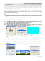
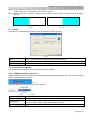
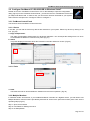
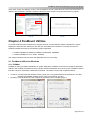
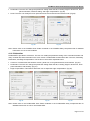
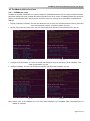
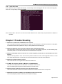
Projected Capacitive Input (PCI) User Guide Version: 1.2 Released date: 2014 / 3 Preface Disclaimer The information in this document is subject to change without notice. The manufacturer makes no representations or warranties regarding the contents of this manual and specifically disclaims any implied warranties of merchantability or fitness for any particular purpose. Furthermore, the manufacturer reserves the right to revise this publication or make changes in the specifications of the product described within it at any time without notice and without obligation to notify any person of such revision. Trademarks AMT, PenMount, Microsoft, Windows and other trademarks and product names used in this manual are the properties of their respective owners and are acknowledged. Copyright This publication, including all photographs, illustrations and software, is protected under international copyright laws, with all rights reserved. Neither this manual, nor any of the material contained herein, may be reproduced without the express written consent of the manufacturer. Copyright 2014 © Apex Material Technology Corp. All rights reserved. Revision Table Date Revision Changes 2012/05 1.0 Initial 2012/09 1.1 Remove the word - "P2" in user guide 2014/03 1.2 Modify PenMount Utilities i Table of Contents Preface................................................................................................................................................................. i Disclaimer.............................................................................................................................................. i Trademarks ........................................................................................................................................... i Copyright ............................................................................................................................................. i Revision Table...................................................................................................................................................... i Table of Contents ................................................................................................................................................ ii Chapter 1 Introduction ....................................................................................................................................... 1 1.1 About this manual ............................................................................................................... 1 1.2 Projected capacitive touch panel ........................................................................................ 1 1.3 PenMount PCI control board .............................................................................................. 1 1.4 Drivers & utilities ................................................................................................................. 1 1.5 Before start using this manual ............................................................................................ 2 1.6 After-sales service .............................................................................................................. 2 Chapter 2 Install Drivers for PenMount PCI Control Board ............................................................................... 2 2.1 PenMount PCI Windows driver ........................................................................................... 2 2.1.1 Install PenMount PCI Windows driver in Windows 7 .......................................................... 2 2.1.2 Uninstall PenMount PCI Windows driver in Window7 ......................................................... 4 2.1.3 Install / uninstall PenMount PCI Linux X Window driver ..................................................... 5 2.1.4 Install / uninstall PenMount PCI WinCE Driver ................................................................... 5 Chapter 3 Configure the Touch Screen ............................................................................................................. 5 3.1 Configure PenMount PCI RS-232/ USB in Windows XP .................................................... 5 3.1.1 PenMount Control Panel ..................................................................................................... 5 3.1.1.1 Device ................................................................................................................................. 5 3.1.1.2 Multiple Monitors ................................................................................................................. 7 3.1.1.3 Tools .................................................................................................................................... 8 3.1.1.4 Screen Rotation Monitor ..................................................................................................... 8 3.1.2 PenMount monitor menu icon ............................................................................................. 8 3.2 Configure PenMount PCI RS-232/USB In Windows Vista/7 .............................................. 9 3.2.1 PenMount Control Panel ..................................................................................................... 9 3.2.1.1 Device ................................................................................................................................. 9 3.2.1.2 Tools .................................................................................................................................... 9 3.2.2 Multiple Monitors ................................................................................................................. 9 Chapter 4 PenMount Utilities ........................................................................................................................... 10 4.1 PenMount utilities for Windows ......................................................................................... 10 4.1.1 PCIMSet ............................................................................................................................ 10 4.1.2 PCIQuickSet ....................................................................................................................... 11 4.1.3 PMUpdate ......................................................................................................................... 12 4.2 PenMount utilities for Linux ............................................................................................... 13 4.2.1 PCIMSet for Linux ............................................................................................................. 13 4.2.2 PmFu for Linux .................................................................................................................. 14 Chapter 5 Trouble Shooting ............................................................................................................................. 14 ii PenMount Projected Capacitive Input User Guide Chapter 1 Introduction PenMount Projected Capacitive Input (PCI) control boards are designed to support projected capacitive touch panels. PenMount offers a series of PCI controller products. PenMount PCI controllers facilitate the high precision touch activation and dual finger gesture recognition with minimum touch force required. PenMount PCI control boards are built with functionalities to operate the PCI touch smoothly. Customers can define their product functions and mechanical requirements by referring to this manual. 1.1 About this manual This manual describes the features of the PenMount PCI control boards, how to operate the utility, and how to install and use the software drivers and utilities with your operating system. This manual is for users who are using PenMount PCI control boards and software, as well as engineers who are integrating and customizing the PenMount PCI control board for use with other products. 1.2 Projected capacitive touch panel AMT provides various sizes of standard PCI touch panels. Customers can find a matching PenMount controller for each PCI touch panel. If the PCI touch is custom designed, the designated PCI control board might be different. For any questions regarding connecting the control board to the touch panel, please check with your system manufacturer. 1.3 PenMount PCI control board PenMount designs control boards for AMT projected capacitive touch panels. Different sizes of PCI touch panels are matched with different PenMount control boards. PenMount controller part numbers and their supported touch panels are as follows: Part No. Touch Screen Size PM2101 COF PM2102 COF PM2201 COF PM1201A PM1300A PM1302 PM1400A PM1401 PM1500 3" - 4.9" 3" - 4.9" 5" - 7.9" 5" - 7.9" 8.0" - 10.4" 8.0" - 10.4" 11" - 15" 11" - 15" 15” - 18.5” Remark: a. This chart is subject to change without prior notice. b. Customized touch panels may be supported by different control boards, which are not listed here. 1.4 Drivers & utilities All PenMount PCI control boards are bundled with software drivers and utilities that support the most common hardware platforms and operating systems. PCIMSet is the initial setting utility for PenMount PCI control board series. PCIMSet allows the user to adjust the controller input interface, touch panel orientation, and touch sensitivity, or check the firmware version. PenMount PCI drivers cannot be installed or operate when PCIMSet is in use. This utility is designed for system integrators and hardware designers. Thus we do not recommend end users to adjust PCI parameters with PCIMSet. End users can use the utility built in the PenMount driver instead. Page 1 of 15 PenMount Projected Capacitive Input User Guide After installing the PenMount PCI driver, the user can use other PenMount touch functions such as edge compensation and linearity test with the utility built in the driver. Please refer to the AMT or PenMount website for the PenMount PCI control board drivers. 1.5 Before start using this manual Make sure the PCI touch panel and PenMount control board have been integrated properly into the computer system. If your need to integrate the control board and touch panel, please refer to the “AMT Projected Capacitive Touch Panel Integration Guide”. 1.6 After-sales service PenMount PCI control board series and software are updated on a regular basis. For more information on the latest updates, downloads, and technical support, please refer to our websites: http://www.amtouch.com.tw http://www.penmount.com.tw Chapter 2 Install Drivers for PenMount PCI Control Board This chapter describes how to install drivers and other software that enables your PenMount PCI control boards to work with various operating systems. PenMount PCI control boards support the following connection interfaces: Part No. USB PM2101 COF PM2102 COF PM2201 COF PM1201A PM1300A PM1302 PM1400A PM1401 PM1500 ● ● ● ● ● ● ● Interface RS-232 UART ● ● ● ● ● ● ● ● ● 2 IC ● ● ● ● ● ● ● ● ● PenMount PCI drivers support most common operating systems of Windows and Linux systems. Please visit our website (http://www.amtouch.com.tw or http://www.penmount.com.tw) to see the O.S supported. 2.1 PenMount PCI Windows driver PenMount provides drivers for the RS-232 and USB interfaces (PenMount-Windows-Universal-Driver-V2.4.1.320WHQL). PenMount drivers can be used on Windows 2000/2003/2008/XP/Vista/7/8. For Windows Vista/7/8, the PenMount control board can be used directly with the built-in USB driver without having to install additional drivers. 2.1.1 Install PenMount PCI Windows driver in Windows 7 Before installing the driver, please connect the PenMount PCI controller via the RS-232 or USB interface. (The driver will be installed according to the interface you are using.) Then, uncompress the file “PenMount-Windows-Universal-Driver-V2.4.1.320WHQL” and begin driver installation following the steps below: Step 1: After extracting the files, run “Setup.exe” (Fig.1). Step 2: When the setup wizard appears, click “Next” to continue (Fig.2). Page 2 of 15 PenMount Projected Capacitive Input User Guide Fig.1 Fig.2 Step 3: When the license agreement appears, click “I Agree” to continue (Fig.3). Step 4: Select the destination folder and click “Install” (Fig.4). Fig.3 Fig.4 Step 5: The dialog window “Would you like to use touch as mouse device?” will appear. If you would like to use the PenMount touch functionality, click “Yes”; if you would like to use the system touch gestures, click “No” (Fig.5). Step 6: If you click “Yes” in step 5, the following window will pop up, indicating the installation is complete. Click “Finish” to exit the window (Fig.6). Fig.5 When the installation is complete, the PenMount icon Fig.6 will be displayed in the notification area. Page 3 of 15 PenMount Projected Capacitive Input User Guide If you click “No” in step 5, the following dialog window will appear. Click “Finish” to exit the window (Fig.7). When the installation is complete, the “PenMount Control Panel” icon will appear on the desk top (Fig.8). Fig.7 Fig.8 2.1.2 Uninstall PenMount PCI Windows driver in Window7 Please follow the steps below to uninstall the PenMount PCI Windows driver: Step 1: In “Control Panel “, choose “Uninstall or change a program”. Find “PenMount Windows Universal Driver V2.4.1.320 (WHQL)”, and click “Uninstall/Change” (Fig.9). Step 2: When the following dialog appears, click “Next” to remove the driver (Fig.10). Fig.9 Fig.10 Step 3: The system will uninstall the driver (Fig.11). Step 4: A dialog window will appear, indicating the driver has been uninstalled. Click “Finish” to exit (Fig.12). Fig.11 Fig.12 Page 4 of 15 PenMount Projected Capacitive Input User Guide 2.1.3 Install / uninstall PenMount PCI Linux X Window driver Before installing PenMount PCI Linux X Window Driver for PenMount control boards, you must have Linux X Window installed and running on your computer. You must also have PenMount Serial Interface either PM2101, PM2102, PM2201 PCI COF and PM1201A, PM1300A, PM1302, PM1400A, PM1401 and PM1500 control boards installed. PenMount PCI Linux X Window Driver for PCI control boards support various operating systems. The supported Linux versions are listed on our website. Please visit http://www.amtouch.com.tw or http://www.penmount.com.tw to view the supported Linux versions. Please refer to the read me file included in the driver folder for further details. 2.1.4 Install / uninstall PenMount PCI WinCE Driver Before installing PenMount WinCE Driver, you must have WinCE system installed and running on your device. You must also have PenMount Serial Interface such as PM2101, PM2102, PM2201 PCI COF and PM1201A, PM1300A, PM1302, PM1400A, PM1401 or PM1500 control boards installed. Please see the read me file included in the driver folder for further details. Chapter 3 Configure the Touch Screen This section describes how to configure the PenMount device after it is installed to windows environment. PenMount driver provides various functions to test and enhance the controller performance under windows environment. 3.1 Configure PenMount PCI RS-232/ USB in Windows XP Right-click on the PenMount monitor icon configure the touch screen. (Fig.13) in the notification area and select “Control Panel” from the menu to Open PenMount Control Panel. The PenMount PCI USB icon can be accessed under the “Device” tab. In the Device tab, you can see the devices detected on your system. Select a device and press the “Configure” to set the configuration. (Fig.14) Fig.13 Fig.14 3.1.1 PenMount Control Panel The functions under “PenMount Control Panel” are described below. 3.1.1.1 Device In this tab, you can find out how many devices are detected on your system. Select any device by clicking on its icon. (Fig.15) Page 5 of 15 PenMount Projected Capacitive Input User Guide Fig.15 a. Setting Operation Mode Beep Sound This mode enables and disables the mouse’s ability to drag on-screen icons—useful for configuring POS terminals. Pen Input Emulation – When this mode is selected, the mouse will emulate Windows Vista pen input device operation. No mouse event will be sent until the touch is dragged out of range or released from the screen. Click on Touch – When this mode is selected, the mouse only provides the click function; dragging is disabled. Mouse Emulation – When this mode is selected, the mouse functions as normal and allows dragging of icons. Click on Release – When this mode is selected, the mouse only provides a click function when the touch is released. Beep Sound checkbox– Enables/disables beep function. Beep on pen down – Beep occurs when the pen comes down. Beep on pen up – Beep occurs when the pen is lifted. Beep on both – Beep occurs when comes down and is lifted up. Beep Frequency – Modifies sound frequency. Beep Duration – Modifies sound duration. Kind of Sound – Selects beep sound type. Cursor Stabilizer Enables/disables the function support to prevent cursor from shaking. checkbox Use press and hold You can set the time out and area to your needs. as right click b. Edge Compensation This page is the edge compensation settings for the advanced calibration. You can adjust the settings from 0 to 30 to accommodate the difference of each touch panel. If the edge area has difficulty detecting touch, please increase the value. If the sensing point shifts too much in the edge area, please decrease this value. (Fig.16) c. About This tab displays information about the PenMount controller and driver version. (Fig.17) Fig.16 Fig.17 Page 6 of 15 PenMount Projected Capacitive Input User Guide 3.1.1.2 Multiple Monitors Multiple Monitors supports two to four touch screen displays for one system. Each monitor requires its own PenMount PCI control board, either installed inside the display or in a central unit. The PenMount PCI control boards must be connected to the computer’s RS-232 or USB ports. Driver installation procedures are the same as installation procedures for a single monitor. Before using Multiple Monitors, you must have two or more monitors that are in extension mode. For display cards that support multiple monitors, we recommend using Matrox, nVidia, or ATI cards and inquiring about operation and usability issues in advance. Note: The Multiple Monitors function is for the use with multiple displays only. Do not use this function if you have only one touch screen display. Please note once you turn on this function, the Rotating function will be disabled. Before using multiple monitors, you need to map each monitor. Follow the steps below to enable multiple displays: Step 1: In PenMount Control Panel, under Multiple Monitors tag, check the “Multiple Monitor Support” box. Then click “Map Touch screens” to assign touch controllers to displays. (Fig.18) Step 2: When the mapping screen message appears, click “OK”. (Fig.19) Step 3: Touch each screen as it displays the message “Please touch this monitor. Press “S” to skip. Follow this sequence and touch each screen to map the touch screens. (Fig.20) Please touch this monitor. Press ‘S’ to skip Fig.18 Fig.19 Fig.20 Note: If you change the resolution of display or screen address, you have to redo Map Touch screens so the system understands where the displays are. If you have multiple monitors but only one touch screen, press ”S” to skip the mapping step. Step 4: An Example for 2 Units of Touch Monitor. Please make sure the touch monitor is plugged in and detected. (Fig.21 & 22) Step 5: In PenMount Control Panel, under Multiple Monitors tag, click “Map Touch screens” then click “OK”. (Fig.23) Fig.21 Fig.22 Fig.23 Page 7 of 15 PenMount Projected Capacitive Input User Guide Step 6: Please follow the message shown on the display to match the controller and the touch screen. Click “S” to skip if the monitor is not used as a touch screen. (Fig.24) Step 7: When screen jump to Screen 2, please touch it. If screen 2 has no touch function, press “S” to skip it. (Fig.25) Fig.24 Fig.25 3.1.1.3 Tools The buttons on “PenMount Control Panel” have the following functions: (Fig.26) Fig.26 Draw : Right Button Icon : Double Click Speed : Tests or demonstrates the PenMount touch screen operation. Enable right button function. The icon can show on Desktop or in the notification area. Adjustable Double click operation speed. 3.1.1.4 Screen Rotation Monitor The function supports nVidia, Intel, or ATI rotation automatic detection. 3.1.2 PenMount monitor menu icon PenMount Monitor icon (PM) appears in the notification area of Windows XP system when you turn on PenMount Monitor in PenMount utility. (Fig.27) Fig.27 PenMount Monitor has the following functions: (Fig.28) Control Panel: Beep: Right Button: Exit: Fig.28 PenMount Control Panel. Beep setting for each device. When this function is selected, a mouse icon appears in the upper right of screen. Click this icon to switch between Right and Left Button functions. Exits the PenMount Monitor function. Page 8 of 15 PenMount Projected Capacitive Input User Guide 3.2 Configure PenMount PCI RS-232/USB In Windows Vista/7 Double-click on the “PenMount Control Panel” icon on the Desktop to open the configuration utility. (Fig.29) On the “PenMount Control Panel”, you will see the icon of PenMount PCI RS-232 (or USB) under Device tab. In “Device” tab, you can see the “devices” detected on your system. Select a device and press the “Configure” button to configure it. Fig.29 3.2.1 PenMount Control Panel The functions under PenMount Control Panel are: 3.2.1.1 Device In this tab, you can find out how many devices are detected on your system. Select any device by clicking on its icon. (Fig.30) a. Edge Compensation The edge compensation settings allow for advanced calibration. You can adjust the settings from 0 to 30 to accommodate the difference of each touch panel. (Fig.31) b. About This panel displays information about the PenMount controller and driver version. (Fig.32) Fig.30 Fig.31 Fig.32 3.2.1.2 Tools Fig.33 a. Draw The Draw tool tests or demonstrates the PenMount touch screen operation. (Fig.33) 3.2.2 Multiple Monitors In Windows Vista/7 environment, if you installed PenMount controller as a digitizer device, you will need to use Multiple Monitors control functions provided by Microsoft to set the touch panel and monitor pairs. Here are the operating steps (Fig.34): Step 1: Open Control Panel Step 2: Find Tablet PC Settings and click Step 3: Hit Setup Button Page 9 of 15 PenMount Projected Capacitive Input User Guide Touch each screen as it displays “If this is not the Tablet PC screen. Press Enter to move to the next screen. To close the tool, press Esc. Follow the sequence and touch each screen to map the touch screens. (Fig.35) Fig.34 Fig.35 Chapter 4 PenMount Utilities To provide customers with comprehensive support services, we offer different utilities to distributors, system integrators, and end users, allowing for the easy use of PenMount PCI solutions. There are two series of PenMount Utilities according to the operating system supported. PenMount Utilities for Windows: PCIMSet, PCIQuickSet, PMUpdate PenMount Utilities for Linux: PmFu, PCIMSet This chapter introduces the functions and applicable users for each utility. 4.1 PenMount utilities for Windows 4.1.1 PCIMSet PCIMSet is mainly provided to distributors or system integrators. PCIMSet can be used to modify the parameter setting of the controller firmware and verify controller firmware information such as its version. PCIMSet contains four tabs: Common, Sensitivity, Parameters, and Panel. The function of each tab is explained below: Common: This tab shows the firmware version, panel size, cover glass thickness, and interface; it can also compute the standard deviation for the current environment. (Fig.36) Sensitivity: This tab allows the user to adjust the sensitivity of the controller. (Fig.37) Fig.36 Fig.37 Page 10 of 15 PenMount Projected Capacitive Input User Guide Parameters: The user can change the parameter setting under this tab, including single or dual-touch, touch panel orientation, interface setting, and edge compensation. (Fig.38) Panel: The user can modify the touch panel size and cover lens thickness under this tab. (Fig.39) Fig.38 Fig.39 Note: Please refer to the PCIMSet User Guide contained in the PCIMSet Utility compressed file for detailed instructions on how to use PCIMSet. 4.1.2 PCIQuickSet PCIQuickSet is provided to customers. The user can modify the parameter setting of the controller firmware and verify controller firmware information such as its version. PCIQuickSet contains three tabs: Common, Sensitivity, Parameters, and Edge Compensation. The function of each tab is explained below: Common: This tab shows the firmware version, panel size, cover glass thickness, and interface. (Fig.40) Parameters: The user can change the parameter setting under this tab, including single or dual-touch, touch panel orientation, and sensitivy. (Fig.41) Edge Compensation: This feature allows the user to adjust the edge compensation. (Fig.42) Fig.40 Fig.41 Fig.42 Note: Please refer to the PCIQuickSet User Guide contained in the PCIQuickSet Utility compressed file for detailed instructions on how to use PCIQuickSet. Page 11 of 15 PenMount Projected Capacitive Input User Guide 4.1.3 PMUpdate PMUpdate allows the user to update the controller firmware version and modify or save the controller firmware setting. PMUpdate contains three tabs: Field Update and Parameter Update, Field Update Only, and Parameter Update Only. The function of each tab is explained below: Field Update and Parameter Update: The user can modify the firmware and modify or save the controller parameter setting. (Fig.43) Fig.43 Field Update Only: The user can modify the firmware setting. (Fig.44) Fig.44 Parameter Update Only: The user can modify or save the controller parameter setting. (Fig.45) Fig.45 Note: Please refer to the PMUpdate User Guide contained in the PMUpdate Utility compressed file for detailed instructions on how to use PMUpdate. Page 12 of 15 PenMount Projected Capacitive Input User Guide 4.2 PenMount utilities for Linux 4.2.1 PCIMSet for Linux PCIMSet is provided to distributors or system integrators. PCIMSet allows the user to modify controller firmware parameter setting and verify controller firmware information such as its version. PCIMSet provides four functions: Display controller information, Specify sensor size and cover lens, Change touch parameters, and Advanced settings. Display controller information: This function allows the user to verify the controller firmware version, panel size, cover lens thickness, and the controller interface. (Fig.46) Specify sensor size and cover lens: The user can modify panel size and cover lens thickness. (Fig.47) Fig.46 Fig.47 Change touch parameters: The user can modify the setting for single or dual touch, panel orientation, and edge compensation. (Fig.48) Advanced settings: The user can modify the interface and adjust the sensitivity. (Fig.49) Fig.48 Fig.49 Note: Please refer to the PCIMSet for Linux User Guide attached in the PCIMSet Utility compressed file for details on operation. Page 13 of 15 PenMount Projected Capacitive Input User Guide 4.2.2 PmFu for Linux PmFu allows the user to update the firmware. The following window will appear after the file is opened (Fig.50). Select the corresponding firmware to update. Fig.50 Note: Please refer to the PmFu for Linux User Guide attached in the PmFu Utility compressed file for details on operation. Chapter 5 Trouble Shooting 1. What is the construction of AMT PCI touch sensors? The current AMT PCI sensor constructions are either two or three layers of ITO film laminated to the top glass, otherwise known as GFF (Glass-Film-Film) or GFFF(Glass-Film-Film-Film) type. 2. What is the purpose of the rear side conductive layer of PCI touch sensor? The bottom layer conductive film of the PCI touch panel is for EMI shielding purposes; the EMI shielding layer averts the system or LCD noise and ensures accurate detection of signals. 3. What is the bending radius of the PCI tail? Is there anything in particular we should take note of for the tail? The tail’s bending radius is 1mm. The PCI touch panel is sensitive to noise. If the tail gets too close to or come into contact with the bezel or metal case, it will cause interference to the PCI touch detection. 4. What is the surface hardness of PCI? The surface of PCI is cover glass with a hardness of MOHS 5. 5. Do AMT PCI solutions operate on Windows 7 and Windows 8? Yes, AMT PCI USB products use Windows 7 or Windows 8 inbox driver. AMT PCI RS232 products please install PenMount Universal Driver. 6. What should the length of the tail be on the PCI touch sensor? The shorter the better. A shorter tail reduces interferences between the electronic components. 7. What kinds of surface treatments are available for PCI touch sensors? Clear, AG (Antiglare), AR(Anti-reflection), and AS(Anti-smudge). Page 14 of 15 PenMount Projected Capacitive Input User Guide 8. Can projected capacitive touch screen be operated when there is liquid on the surface? Sometimes liquid on the surface of a projected capacitive touch screen might cause malfunction, which is a limit yet to be overcome for projected capacitive touch technology. When there is water on the surface of the PCI touch panel, please wipe it dry. Then the PCI will function properly. 9. Can I operate a projected capacitive touch screen with gloved fingers? AMT PCI touch panels with PenMount PCI control boards are able to support gloved finger operation by certain kinds of gloves including latex gloves for medical and clean room, household latex gloves, cotton gloves, and work gloves. 10. Is it ok if there’re objects on the surface of the touch panel while rebooting? When the system is rebooting, no objects (such as hands) should be on the surface of the touch sensor. 11. What is the capacitance technology that PenMount projected capacitive touch controllers employ? PenMount projected capacitive touch controllers are based on mutual capacitance technology and locate touches with the driving and sensing lines laid out on the two conductive layers of the touch sensor. 12. Do PenMount’s projected capacitive touch controllers work with the touch sensors made by other manufacturers? PenMount’s projected capacitive touch controllers can work with any touch sensors designed to meet the requirements of PenMount controllers. Please contact our sales staff for further information. 13. If customers would like to design in the PCI IC onto their system main board, can AMT support this kind of design? In general, we are able to support customers to design in the PCI IC on their system main board. Please contact our sales staff. 14. Which hardware platforms do PenMount PCI drivers support? All PenMount PCI drivers are based on the x86 system and ARM-based Linux embedded system. Please contact our sales staff for other hardware platform requirements. 15. Will PenMount support ARM-based Linux and Android OS? Can PenMount provide the drivers? Yes. If you use ARM hardware platform, it is the Reduced Instruction Set Computing (RISC). You can contact our sales staff if you have needs. You will need to fill out the company profile information and sign the NDA. PenMount will provide the source code for you to develop drivers for our PenMount devices successfully. 16. How do I enable multi-touch on Linux or Android? For Linux, PenMount USB devices are supported by the inbox driver of Linux Kernel 3.0, and PenMount RS232 interface is supported by the inbox driver from Linux kernel 3.2. For other Linux and Android operating systems, you can drive the PenMount hardware devices with PenMount driver source code and enable multi-touch functionality with Linux/Android multi-touch application programs. Page 15 of 15