1
HT-IDE3000 User’s Guide
February 2014
Copyright © 2013 by the company. All rights reserved. Printed in Taiwan. No part of this publication
may be reproduced, stored in a retrieval system, or transmitted in any form by any means, electronic,
mechanical photocopying, recording, or otherwise without the prior written permission of the company
NOTICE
The information appearing in this User’s Guide is believed to be accurate at the time of publication.
However, the company assumes no responsibility arising from the use of the specifications described. The
applications mentioned herein are used solely for the purpose of illustration and the company makes no
warranty or representation that such applications will be suitable without further modification, nor
recommends the use of its products for application that may present a risk to human life due to malfunction
or otherwise. the company’s products are not authorized for use as critical components in life support
C
o
n
t
e
devices or systems. the company reserves the right to alter its products without prior notification.
ii
n
t
s
Contents
Contents
P a r t I................................................................................................ 1
C h a p t e r 1 ................................................................................................................................... 3
IDE Development Environment ....................................................................................... 3
In-Circuit Emulator - ICE, e-ICE and e-Link ................................................................. 5
ICE Interface Card................................................................................... 5
System Configuration ........................................................................................................ 6
Installation ............................................................................................................................ 7
System Requirement ............................................................................... 7
Hardware Installation............................................................................... 7
Software Installation ................................................................................ 8
Driver digital signature ........................................................................... 11
C h a p t e r 2 ................................................................................................................................. 13
Step 1:Create a New Project with the CodeWizard ............................................... 13
Step 2:Build the Project................................................................................................ 13
Step 3:Programming the MCU Device ..................................................................... 14
Step 4:Transmit Code to the company ..................................................................... 14
C h a p t e r 3 ................................................................................................................................. 17
Start the HT-IDE3000 System ....................................................................................... 17
File Menu ............................................................................................................................ 19
Edit Menu ........................................................................................................................... 20
View Menu.......................................................................................................................... 21
Tools Menu ........................................................................................................................ 22
Configuration Option ............................................................................. 23
i
C
o
n
t
e
n
t
s
Import Configuration Options................................................................. 23
Diagnose ............................................................................................... 23
Library Manager .................................................................................... 25
Holtek C V2-->V3 syntax converter ....................................................... 25
Program Location Manager ................................................................... 27
Editor ..................................................................................................... 29
LCD Simulator ....................................................................................... 32
Voice & Flash Download ....................................................................... 32
Switch OCDS Mode .............................................................................. 32
Smart Programming Settings ................................................................ 32
Options Menu .................................................................................................................... 33
Project Settings ..................................................................................... 34
Editor Settings ....................................................................................... 41
Language .............................................................................................. 42
Customise ............................................................................................. 43
e-Link Activation .................................................................................... 43
Bookmarks ......................................................................................................................... 47
Bookmarks Window............................................................................... 47
Bookmark Window Toolbar ................................................................... 47
Bookmark menu .................................................................................... 48
C h a p t e r 4 ................................................................................................................................. 51
Create a New Project....................................................................................................... 52
Step1: Project Location ......................................................................... 52
Step2: Project Option ............................................................................ 53
Step3: Project Deployment .................................................................... 54
Open and Close a Project .............................................................................................. 55
Manage the Source Files of a Project.......................................................................... 55
To Add a Source File to the Project ....................................................... 56
To Delete a Source File from the Project .............................................. 56
To Move a Source File Up or Down ...................................................... 56
Build a Project’s Task Files ............................................................................................ 57
To Build a Project Task File................................................................... 58
To Rebuild a Project Task File .............................................................. 58
Assemble/Compile ........................................................................................................... 58
To Assemble or Compile a Program ..................................................... 58
Print Option Table Command ........................................................................................ 59
ii
C
o
n
t
e
n
t
s
Backup/Restore Project .................................................................................................. 60
C h a p t e r 5 ................................................................................................................................. 63
Reset the HT-IDE3000 System ..................................................................................... 64
To Reset from the HT-IDE3000 Commands.......................................... 65
Emulation of Application Programs .............................................................................. 65
To Emulate the Application Program ..................................................... 66
To Stop Emulating the Application Program .......................................... 66
To Run the Application Program to a Line ............................................. 66
To Directly Jump to a Line of an Application Program ........................... 66
Single Step ......................................................................................................................... 67
Breakpoints ........................................................................................................................ 68
Breakpoint Features .............................................................................. 68
Description of Breakpoint Items............................................................. 69
How to Set Breakpoints ......................................................................... 71
Trace the Application Program ...................................................................................... 73
Initiating the Trace Mechanism.............................................................. 73
Stopping the Trace Mechanism ............................................................. 76
Trace Start/Stop Setup .......................................................................... 76
Trace Record Format ............................................................................ 79
C h a p t e r 6 ................................................................................................................................. 83
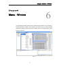
Window Menu Commands ............................................................................................. 84
P a r t I I............................................................................................ 93
C h a p t e r 7 ................................................................................................................................. 95
Notational Conventions ................................................................................................... 95
Statement Syntax ............................................................................................................. 96
Name ..................................................................................................... 96
Operation............................................................................................... 97
Operand ................................................................................................ 97
Comment ............................................................................................... 97
Assembly Directives ......................................................................................................... 97
Conditional Assembly Directives ........................................................... 97
File Control Directives ........................................................................... 98
Program Directives .............................................................................. 100
iii
C
o
n
t
e
n
t
s
Data Definition Directives .................................................................... 103
Macro Directives.................................................................................. 105
Assembly Instructions .................................................................................................... 107
Name ................................................................................................... 107
Mnemonic ............................................................................................ 108
Operand, Operator and Expression ..................................................... 108
Miscellaneous .................................................................................................................. 110
Forward References ............................................................................ 110
Local Labels ........................................................................................ 110
Reserved Assembly Language Words ................................................ 112
Cross Assembler Options ............................................................................................. 113
Assembly Listing File Format ....................................................................................... 114
Source Program Listing ....................................................................... 114
Summary of Assembly ........................................................................ 115
Miscellaneous...................................................................................... 115
C h a p t e r 8 ............................................................................................................................... 117
What the Cross Linker Does ........................................................................................ 117
Cross Linker Options ..................................................................................................... 117
Libraries .............................................................................................. 118
Section Address .................................................................................. 118
Generate Map File............................................................................... 119
Linker Options ..................................................................................... 119
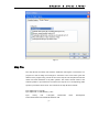
Map File ............................................................................................................................ 120
Cross Linker Task File and Debug File ..................................................................... 122
P a r t I I I ........................................................................................ 125
C h a p t e r 9 ............................................................................................................................... 127
What the Library Manager Does ................................................................................. 127
To Setup the Library Files ............................................................................................ 127
Create a New Library File .................................................................... 128
Add a Program Module into a Library File ........................................... 129
Delete a Program Module from a Library File ...................................... 129
Extract a Program Module from Library and Create An Object File ..... 130
Object Module Information .................................................................. 130
iv
C
o
n
t
e
n
t
s
P a r t I V ........................................................................................ 131
A p p e n d i x A ........................................................................................................................... 133
Reserved Assembly Language Words ...................................................................... 133
Instruction Sets ............................................................................................................... 135
v
Part I Integrated Development Environment
PartI
Integrated Development
Environment
1
Part I Integrated Development Environment
2
Chapter 1 Overview and Installation
Chapter1
Overview and Installation
1
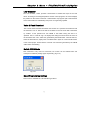
To ease the process of application development, the importance and availability of
supporting tools for microcontrollers cannot be underestimated. To support its range of
MCUs, the company is fully committed to the development and release of easy to use and
fully functional tools for its full range of devices. The overall development environment is
known as the IDE, while the operating software is known as the HT-IDE3000. The
software provides an extremely user friendly Windows based approach for program
editing and debugging while the ICE and e-ICE emulators and OCDS hardware provides
full real time emulation with multi functional trace, stepping and breakpoint functions. With
a complete set of interface cards for its full device range and regular software Service
Pack updates, the IDE development environment ensures that designers have the best
tools to maximize efficiency in the design and release of their microcontroller applications.
IDE Development Environment
The
Integrated Development Environment, otherwise known as the IDE, is a high
performance integrated development environment designed around the company’s series
of 8-bit MCU devices. Incorporated within the system is the hardware and software tools
necessary for rapid and easy development of applications based on the company range
of 8-bit MCUs. The key component within the IDE system is the ICE, e-ICE or OCDS
Emulators and Debuggers, capable of emulating the company
8-bit MCU in real time, in
addition to providing powerful debugging and trace features. As for the software, the
HT-IDE3000 provides a friendly workbench to ease the process of application program
development, by integrating all of the software tools, such as editor, Cross Assembler,
Cross Linker, library and symbolic debugger into a user friendly Windows based
3
Chapter 1 Overview and Installation
environment. In addition, the HT-IDE3000 provides a software simulator for some devices
which is capable of simulating the behavior of the company’s 8-bit MCU range without
connection to a hardware emulator.
More detailed information on the HT-IDE3000 development system is contained within
the HT-IDE3000 User’s Guide. Installed in conjunction with the HT-IDE3000 and to
ensure that the development system contains information on new microcontrollers and
the latest software updates, the company provides regular HT-IDE3000 Service Packs.
These
Service Packs, which can be downloaded from the the company website, do not replace
the
HT-IDE3000 but are installed after the HT-IDE3000 system software has been installed.
Some of the special features provided by the HT-IDE3000 include:
Emulation
Real-time program instruction emulation
Hardware
ICE
Easy installation and usage
Either internal or external oscillator
Breakpoint mechanism
Trace functions and trigger qualification supported by trace emulation chip
Printer port for connecting the ICE to a host computer
I/O interface card for connecting the user’s application board to the ICE
e-ICE
Easy installation and usage
Either internal or external oscillator
Breakpoint mechanism
USB cable for connecting the e-ICE to a host computer
2.54mm standard pins for connecting the user’s application board to the e-ICE
e-Link
The EV uses an OCDS - On-Chip Debug Support - architecture, which only requires
two signal lines for debug
The EV has the same number of pins as the IC or 1~2 more pins than the IC. It can be
soldered to the application board and easily debugged.
Contains several types of breakpoint functions
Includes RAM real-time monitoring function
Wide operating voltage range of 1.7V~5.5V
4
Chapter 1 Overview and Installation
Software
Windows based software utilities
Source program level debugger - symbolic debugger
Workbench for multiple source program files – allows for more than one source
program file in one application project
All tools are included for the development, debug, evaluation and generation of the
final application program code
Library for the setting up of common procedures which can be linked at a later date to
other projects.
In-Circuit Emulator - ICE, e-ICE and e-Link
Developed alongside the the company 8-bit microcontroller device range, the company
ICE is a fully functional in-circuit emulator for the company’s 8-bit microcontroller devices.
Incorporated within the system are a comprehensive set of hardware and software tools
for rapid and easy development of user applications. Central to the system is the in-circuit
hardware emulator, capable of emulating all of the company’s 8-bit devices in real-time,
while also providing a range of powerful debugging and trace facilities. Regarding
software functions, the system incorporates a user-friendly Windows based workbench
which integrates together functions such as program editor, Cross Assembler, Cross
Linker and library manager.
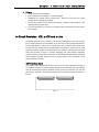
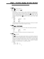
ICE Interface Card
The interface cards supplied with the ICE can be used for most applications, however, it
is possible for the user to omit the supplied interface card and design their own interface
card. By including the necessary interface circuitry on their own interface card, the user
has a means of directly connecting their target boards to the CN1 and CN2 connectors of
the ICE.
Fig 1-1
5
Chapter 1 Overview and Installation
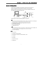
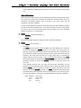
System Configuration
The IDE system configuration is shown below, in which the host computer is a
Pentium compatible machine with Windows 2000/XP or later. Note that if
Windows 2000/XP or later systems are used, then the HT-IDE3000 software must
be installed in the Supervisor Privilege mode.
Power Adapter
Emulator
Flat Cable
Printer Cable
Emulator Box
HT-ICE
Interface
Card
Target
Board
HandyWriter
Fig 1-2
The IDE system contains the following hardware components:
ICE
The ICE box contains the emulator box with 1 printer port connector for connecting to
the host machine, I/O signal connector and one power-on LED
I/O interface card for connecting the target board to the ICE box
Power Adapter, output 16V
25-pin D-type printer cable
Integrated MCU writer
e-ICE
The e-ICE basically consists of two boards, a mother board, known as the MEV, and
into which is plugged a device daughter board, known as the DEV.
5-pin Mini-B USB cable
e-Link
e-Link device
2×6 double row male headers
Flat-Cable pin connector 2×6 female headers - 25cm
e-FPC06A
USB cable
Important note card
Software CD
6
Chapter 1 Overview and Installation
Installation
System Requirement
The hardware and software requirements for installing HT-IDE3000 system are as
follows:
PC/AT compatible machine with Pentium or higher CPU
SVGA color monitor
At least 256M RAM for best performance
CD ROM drive (for CD installation)
At least 200M free disk space
Parallel or USB port to connect PC and ICE
Windows XP/Vista/7
* Windows XP/Vista/7 are trademarks of Microsoft Corporation
Hardware Installation
The company provides three kinds of ICE for the user to choose, as follows:
ICE
Step 1
Plug the power adapter into the power connector of the ICE
Step 2
Connect the target board to the ICE by using the I/O interface card or flat cable
Step 3
Connect the ICE to the host machine using the printer cable. The LED on the ICE
should now be lit, if not, there is an error and your dealer should be contacted.
Caution:
Exercise care when using the power adapter. Do not use a power adapter whose output
voltage is not 16V, otherwise the ICE may be damaged. It is strongly recommended that
only the power adapter supplied by the company be used. First plug the power adapter to
the power connector of the ICE.
e-ICE
Step 1
Install the correct DEV board for the MCU to be emulated
Step 2
7
Chapter 1 Overview and Installation
Use the USB cable to connect the e-ICE to the PC. The LED on the ICE should now be lit,
if not, there is an error and your dealer should be contacted.
e-Link
Step 1
Connect the EV board to the e-Link using the flat cable
Step 2
Use the USB cable to connect the e-Link to the PC. The LED on the e-Link should
now be lit, if not, it must be reconnected or contact your agent.
Caution:
The HT-IDE3000 software version must be 7.6 or above when using the e-Link to debug.
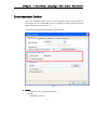
Software Installation
Step 1
First click on the HT-IDE3000 install icon to start the
HT-IDE3000 installation.
Step 2
Press the <Next> button to continue setup or press <Cancel> button to abort.
Fig 1-6
Step 3
The following dialogue will be shown to ask the user to enter a directory name.
8
Chapter 1 Overview and Installation
Fig 1-7
Fig 1-8
Step 4
Specify the path you want to install the HT-IDE3000 to and click the <Next> button.
Step 5
SETUP will copy all files to the specified directory.
9
Chapter 1 Overview and Installation
Fig 1-9
10
Chapter 1 Overview and Installation
Step 6
If the process is successful the following dialogue box will be shown.
Fig 1-10
Step 7
Press the <OK> button and then press the <Finish> button to finish the setup. If this is
the first installation of HT-IDE3000, please restart the computer system.
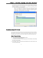
Driver digital signature
During the setup, note that the driver digitial signature is a protection mechanism for
Win7 driver installation. If a problem should occur the solution is as follows:
Restart the computer, then press the F8 key, select "Disable Driver Signature
Enforcement" to enter the system, and then setup the HT-IDE3000. In addition, if the
ICE can not be connected, it also needs to select "Disable Driver Signature
Enforcement" to enter the system.
11
Chapter 1 Overview and Installation
12
Chapter 2 Quick Start
Chapter2
2
Quick Start
This chapter gives a brief description of using HT-IDE3000 to develop an application
project.
Step 1:Create a New Project with the CodeWizard
Click on the Project menu and select New command
Enter a project name and select an MCU from the combo box
Choose the file type from either .ASM or .C.
Click on the Next button and the system will ask you to setup the configuration options
Setup all configuration options and click on the OK button.
Finally, click OK when you have confirmed the Project Setting options.
Step 2:Build the Project
Click on Build menu and select the Build command
The system will assemble/compile all source files in the project
If there are errors in the programs, double click on the error message line and the
system will prompt you to the position where the error has occurred.
If all the program files are error free, the system will create a Task file and
download it to the ICE for debug.
These steps can be repeated until the program is fully debugged.
13
Chapter
2
Quick
Start
Step 3:Programming the MCU Device
Build the project to create the .OTP file
Use the general-purpose writer e-WriterPro together with the HOPE3000 to program
the MCU devices.
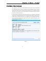
Step 4:Transmit Code to the company
Click on the Project menu and select the Option Table Viewer command. Fig 2-1 will
then be displayed, after which click on the Print button to print the configuration
options.
Send the .COD file and the Option Approval Sheet to the company.
Fig 2-1
The Programming and data flow is illustrated by the following diagram:
14
Chapter
Fig 2-2
15
2
Quick
Start
Chapter 3 Menu – File/Edit/View/Tools/Option
Chapter3
Menu
File/Edit/View/Tools/Options
3
This chapter describes some of the menus and commands of the HT-IDE3000. Other
menus are described in the Project, Debug and Window chapters.
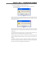
Start the HT-IDE3000 System
Fig 3-1
Click the Start Button, select Programs and select HT-IDE3000
Click the HT-IDE3000 icon
17
Chapter 3 Menu – File/Edit/View/Tools/Option
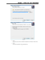
Fig 3-2 will be displayed if the following conditions occur.
No connection between the ICE and the host machine or connection fails.
The ICE is powered off.
Fig 3-2
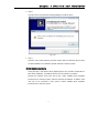
If “Retry” is selected and the connection between the ICE and the host machine has been
made, then Fig 3-3 will be displayed, the HT-IDE3000 will enter the emulation mode and
the ICE begins to function.
Fig 3-3
The HT-IDE3000 software includes File, Edit, View, Project, Build, Debug, Tools, Options,
Window and Help menus. The following sections describe the functions and commands
of each menu.
A dockable toolbar, below the menu bar (Fig 3-4), contains icons that correspond to, and
assist the user with more convenient execution of frequently used menu
commands. When the cursor is placed on a toolbar icon, the corresponding command
name will be displayed alongside. Clicking on the icon will cause the command to be
executed.
A Status Bar, in the bottom line (Fig 3-4), displays the emulation or simulation present
status and the resulting command status. In the status bar, the field (PC=0001H) displays
the Program Counter while in debugging process (Debug menu).
18
Chapter 3 Menu – File/Edit/View/Tools/Option
Fig 3-4
The Status Bar contains information that may be useful during program debug. The
Program Counter is used during program execution and indicates the actual present
Program Counter value while the row and column indicators are used to show the present
cursor position when using the program editor.
File Menu
The File menu provides file processing commands, the details behind which are shown in
the following list along with the corresponding toolbar icons.
New
Create a new file
Open
Open an existing file
Close
19
Chapter 3 Menu – File/Edit/View/Tools/Option
Close the current active file
Save
Write the active windows data to the active file
SaveAs
Write the active windows data to the specified file
Save All
Write all windows data to the corresponding opened files
Print
Print active data to the printer
Print Setup
Setup printer
PrintPreview
Preview the printed output
Recent Files
List the most recently opened and closed four files
Exit
Exit from HT-IDE3000 and return to Windows
Edit Menu
Undo
Cancel the previous editing operation
Redo
Cancel the previous Undo operation
Cut
Remove the selected lines from the file and place onto the clipboard
Copy
Place a copy of the selected content onto the clipboard
Paste
Paste the clipboard information to the present insertion point
Delete
Delete the selected content
20
Chapter 3 Menu – File/Edit/View/Tools/Option
Select All
Select the entire document
Find
Search the specified word from the editor active buffer
Find Next
Find the next occurrence of the specified text
Find Previous
Find the previous occurrence of the specified text
Find in Files
Search for a string in multiple files
Replace
Replace the specified source word with the destination word in the editor active buffer
Go To…
Moves to a specified location
Read Only
Read only mode
View Menu
The View menu provides the following commands to control the window screen of the
HT-IDE3000. (Refer to Fig 3-5)
Full Screen
Toggles Full Screen Mode on/off
Appliaction Look
Multiple styles can be selected: Windows 2000, Office XP, Windows XP, Office 2003,
Visual Studio .Net 2005, Office 2007(including blue, black, sliver and green), Visual
Studio .Net 2005 is as the default.
Restore Default LayOut
Restore the default layout, this command will restart the program automatically.
Toolbar
Display the toolbar information on the window. The toolbar contains some groups of
buttons whose function is the same as that of the command in each corresponding
menu item. When the mouse cursor is placed on a toolbar button, the corresponding
function name will be displayed next to the button. If the mouse is clicked, the
21
Chapter 3 Menu – File/Edit/View/Tools/Option
command will be executed. Refer to the corresponding chapter for the functionality of
each button. The Toggle Breakpoint button will set the line specified by the cursor as a
breakpoint (highlighted). The toggle action of this button will clear the breakpoint
function if previously set.
Status Bar
Displays the status bar information on the window.
Display Line Numbers
Toggle line numbering on and off in your code.
Cycle Count
Count instruction cycles accumulatively. Press the reset button to clear the cycle
count. The Hex and Dec buttons are used to change the radix of the count,
hexadecimal or decimal. The maximum cycle count is 65535.
Note: There is a slight difference of maximum cycle count between two kinds of ICE, the
maximum cycle count of e-ICE can up to 4294967295 while ICE can only count to 65535.
Fig 3-5
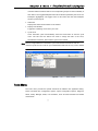
Tools Menu
The Tools menu provides the special commands to facilitate user application debug.
These commands are Configuration Options, Import Configuration Options, Diagnose,
Writer, Library Manager, Editor, LCD Simulator, Voice & Flash Download and Switch
OCDS Mode.
22
Chapter 3 Menu – File/Edit/View/Tools/Option
Fig 3-6
Configuration Option
This command generates an option file used by the Build command in the Build menu.
The contents of the option file depend upon the specified MCU. This command allows
options to be modified after creation of the project.
Choosing the Clock Source
When creating a new project or modifying the configuration options, it is necessary to
choose an internal or external clock source for ICE.
If an internal clock source is used, the system application frequency has to be specified.
The HT-IDE3000 system will calculate a frequency which can be supported by the ICE,
one which will be the most approximate value to the specified system frequency.
Whenever the calculated frequency is not equal to the specified frequency, a warning
message and the specified frequency along with the calculated frequency will be
displayed. Confirmation will then be required to confirm the use of the calculated
frequency or to specify another system frequency. Otherwise an external clock source is
the only option. No matter which kind of clock source is chosen, the system frequency
must be specified.
Note: More information about choosing the clock source for e-ICE, please refer to the e-ICE
User’s Guide.
Import Configuration Options
Import the configuration options files.
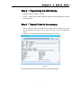
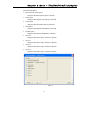
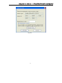
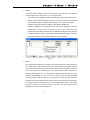
Diagnose
This command (Fig 3-7) helps to check whether the ICE is working correctly. There are a
total of 9 items for diagnosis. Multiple items can be selected by clicking the check
box and pressing the Test button, or press the Test All button to diagnose all items. These
23
Chapter 3 Menu – File/Edit/View/Tools/Option
items are listed below.
MCU resource option space
Diagnose the MCU options space of the ICE.
Code space
Diagnose the program code memory of the ICE.
Trace space
Diagnose the trace buffer memory of the ICE.
Data space
Diagnose the program Data Memory of the ICE.
System space
Diagnose the system Data Memory of the ICE.
I/O EV 0
Diagnose the I/O EV-chip in socket 0 of the ICE.
I/O EV 1
Diagnose the I/O EV-chip in socket 1 of the ICE.
I/O EV 2
Diagnose the I/O EV-chip in socket 2 of the ICE.
I/O EV 3
Diagnose the I/O EV-chip in socket 3 of the ICE.
Fig 3-7
24
Chapter 3 Menu – File/Edit/View/Tools/Option
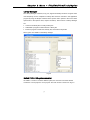
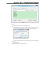
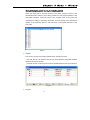
Library Manager
The Library Manager command, in Fig 3-8, supports the library functions. Program codes
used frequently can be compiled into library files and then included in the application
program by using the Project command in the Options menu. (Refer to the Cross Linker
options item in the Options menu, Project command). The functions of Library Manager
are:
Create a new library file or modify a library file
Add/Delete a program module into/from a library file
Extract a program module from a library file, and create an object file
Part III gives more details on the library manager.
Fig 3-8
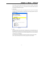
Holtek C V2-->V3 syntax converter
As Holtek’s C V2 and C V3 have different syntax, this converter can assist with the
conversion of C V2 projects to C V3 projects. The main screen is shown in in Fig 3-9
25
Chapter 3 Menu – File/Edit/View/Tools/Option
Fig 3-9
1.
Add
Add a project for conversion. More than one can be added at a single time allowing
multiple projects to be converted at the same time
2.
Remove
Delete the selected project
3.
Clear
Clear all projects
4.
Convert
Start Conversion
5.
Convert To
This only support conversion to Holtek C V3
6.
Settings Save Path
Save the path of the converted project
1) Default
Automatically generates a folder named V3 in the original project folder
2) Other Path
Stored in the user specified path
26
Chapter 3 Menu – File/Edit/View/Tools/Option
7.
To convert the syntax (multiple-choice)
The syntax to be converted is listed below:
1) Absolute Variable
A variable is designated to the fixed address, for example: char a @0x80;
2) Built-in Function
For example: _clrwdt()
3) Flag-Bit
For example: _80_1
4) Delay Function
The built-in function: _delay()
5) Interrupt
Interrupt function
6) Inline Assembly
Embedded assembly language, for example:
#asm
#endasm
7) Bit-Variable
For example:bit a;
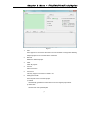
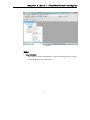
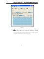
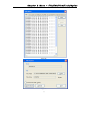
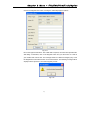
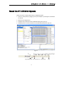
Program Location Manager
The position of each module in the memory can be setup by the user, see Fig 3-10.
27
Chapter 3 Menu – File/Edit/View/Tools/Option
Fig 3-10
1.Type
Types of module. These can be C, ASM, OBJ or LIB.
2.Set
Select modules in listbox (use the Shift key or Ctrl key to select more than one
module) and then click the Set button. This will generate the following dialog:
Fig 3-11
Finally enter the start address and end address.
Tip: Removing the start address and the end address can reset the module settings
3.Reset
Clear all settings
Additionally this can be setup from the workspace.
28
Chapter 3 Menu – File/Edit/View/Tools/Option
.
Fig 3-12
Editor
Voice ROM Editor
The company provides a VROM Editor for the user to arrange the voice code for
the specific MCU (eg. The HT86 series)
29
Chapter 3 Menu – File/Edit/View/Tools/Option
Fig 3-13
Data Editor
Some the company MCUs (eg. the HT48E series) include internal EEPROM
memory. The Data EEPROM Editor provides an interface for the user to arrange
the data and download/upload the data to/from the ICE.
30
Chapter 3 Menu – File/Edit/View/Tools/Option
Fig 3-14
Fig 3-15
31
Chapter 3 Menu – File/Edit/View/Tools/Option
LCD Simulator
The LCD simulator, LCDS, provides a mechanism to simulate the output of the LCD
driver. According to the designed patterns and the control programs, the LCDS displays
the patterns on the screen in real time. LCD Simulator only supports part of MCUs based
on the ICE architecture. Additionally, this part is no longer being updated.
Voice & Flash Download
The Voice & Flash Download downloads the contents of a specified voice data file with
the extension .VOC or .DAT to the ICE for emulation or burn the voice data to SPI Flash
by e-Writer. It also uploads from ICE VROM or SPI Flash saving the data to a
specified .VOC or .DAT file. Fig 3-15 displays the dialog box which shows the name of
the download voice .VOC, which was generated by the VROM editor. The File Size box,
below the File Path box, displays the voice ROM size in bytes for microcontroller device
in the current project. Ensure that the voice file .VOC has been generated by the VROM
editor before downloading.
Switch OCDS Mode
This command is only used for OCDS-ICE, two modes can be selected here and
correspond to different package types respectively. (Fig 3-16).
Fig 3-16
Smart Programming Settings
This function is available for OTP and MTP type MCUs.
32
Chapter 3 Menu – File/Edit/View/Tools/Option
Fig 3-17
This function refers to Chapter four in the HOPE3000 documentation.
Options Menu
The Options menu (Fig 3-18) provides the following commands which can set the working
parameters for other menus and commands.
Fig 3-18
33
Chapter 3 Menu – File/Edit/View/Tools/Option
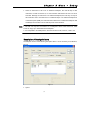
Project Settings
Project Option
The Project Option sets the default parameters used by the Build command in the Project
menu. During development, the project options may be changed according to the needs
of the application. According to the options set, the HT-IDE3000 will generate a proper
task file for these options when the Build command of the Project menu is issued. The
dialog box (Fig 3-19) is used to set the Project options.
Fig 3-19
34
Chapter 3 Menu – File/Edit/View/Tools/Option
Fig 3-20
Note: Before issuing the Build command, ensure that the project options are set correctly.
Micro Controller
The chosen MCU for this project is selected here. Use the scroll arrow to browse the
available MCUs and select the appropriate one.
With Bootloader
This function is only suitable for the USB Flash MCU series.
Check the With BootLoader box when programming in the ISP mode and then select
the program block which is first executed when powered on.
Start at the ISP mode then excute the BootLoader program block first when powered
on Wait until the AP excutes the USB Link, then jump to the User code block when the
update is finished.
Start at theUser mode then excute the User code block first when powered on. Only if
an update is necessary will it call the Library and return to the BootLoader to update. It
35
Chapter 3 Menu – File/Edit/View/Tools/Option
will jump to the new User code block when the update is finished.
Project's Build Option
Clicking on the button will cause the configuration dialog box to be displayed. This is
used to set the Complier options.
Language Tool
The company permits Third Parties to provide C compilers for the company’s MCUs.
Here the Hi-Tech language tool can be selected as an alternative choice.
Assembler/Compiler Options
The command line options of the Cross Assembler. Define symbol allows users to
define values for specified symbols used in assembly programs. The syntax is as
follows:
symbol1[=value1] [,symbol2 [=value2] [,...]]
For example:
debugflag=1,
newver=3
The check box of the Generate listing file is used to check if the source program listing
file has been generated.
Linker options
To specify the options of the Cross Linker. Libraries are used to specify the library files
refered by Cross Linker.For example:
libfile1,
libfile2
Library files can be selected by clicking the Browse button.
Section address is used to set the ROM/RAM addresses of the specified sections, for
example:
codesec=100,
datasec=40
The check box of the Generate map file is used to check if the map file of Cross Linker
is generated.
Debug Command
This command sets the options used by the Debug menu. The dialog box (Fig 3-21) lists
all the debug options with check boxes. By selecting the options and pressing the OK
button, the Debug menu can then obtain these options during the debugging process.
36
Chapter 3 Menu – File/Edit/View/Tools/Option
Fig 3-21
Trace Record Fields
This location specifies the information to be displayed when issuing the Trace List
command, contained within the Window menu. For each source file instruction, the
information will be displayed in the same order as that of the items in the dialog box,
from top to the bottom. If no item has been selected, the next selected item will be
moved forward. The default trace list will display the file name and line number only.
The de-assembled instruction is obtained from the machine code, and the source line
is obtained from the source file.
General
Several items are used to display certain actions when in the debug mode, such as
displaying variable values, hexadecimal displays and downloading EEPROM data.
The Download EEPROM data check box is only checked when the selected IC has an
EEPROM function. If the check box is checked, the EEPROM will be downloaded to
the hardware simulator automatically when executing the Build command.
Auto Stepping Command
Selects the automatic call procedure step option, namely Step Into or Step Over. Only
one option can be selected.
Stack
Uncheck this Detect Stack Overflow box if you do not want the system to show a
37
Chapter 3 Menu – File/Edit/View/Tools/Option
message while detecting a stack overflow.
Connection Port
Display the PC connection port for the ICE. The connection port has no effect if the
simulation mode is selected.
Directories Command
The command sets the default search path and directories for saving files. (Fig 3-22)
Fig 3-22
Include paths
The search path referred to by the Cross Assembler to search for the included files.
Library paths
The search path referred to by the Cross Linker to search for the library files.
Output files path
The directory for saving the output files of the Cross Assembler (.obj, .lst) and Cross
Linker (.tsk, .map, .dbg)
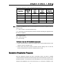
Document
This command is used to add documents to the project. When documents are added,
they will be listed on the Documents window on the left hand side as shown in Fig
38
Chapter 3 Menu – File/Edit/View/Tools/Option
3-25.
Fig 3-23
39
Chapter 3 Menu – File/Edit/View/Tools/Option
Fig 3-24
Fig 3-25
40
Chapter 3 Menu – File/Edit/View/Tools/Option
Production
In order to let users know which IC has been locked, the HT-IDE3000 provides an
identification code function as shown in Fig 3-26.
When the setput is finished, the identification code will be written into the
corresponding document (OTP, MTP, PND) by clicking on the ReBuild All button.
Note:
This function is available for OTP and flash type MCUs
The HT-IDE3000 software version must be 7.71 or above
The Hope3000 software version must be 3.06 or above
Fig 3-26
Editor Settings
Format
This command is used to set the foreground and background colours.From the available
options, shown in Fig 3-27, Text Selection is used for the Edit menu, Current line,
Breakpoint Line, Trace Line and Stack Line are for the Debug menu and Error line is for
41
Chapter 3 Menu – File/Edit/View/Tools/Option
the Assembler output.
Fig 3-27
Editors
This command is used to set the editor options such as tab size, the Undo command
count and some functions’ disable settings. The Save Before Assemble option will save
the file before assembly. The automatic reload of extemally modified files will load the
files automatically which have been modified externally. The Disable Classview option will
not display any information on the classview window. The Disable Suggestions list is
disable variable tip list. The Disable Suggestions Tip is used to disable the function
parameters tip.
Fig 3-28
Language
This command changes the language of the user interface. ‘Default’ is the language of
the operation system.
42
Chapter 3 Menu – File/Edit/View/Tools/Option
Customise
This command can rearrange and modify the toolbar buttons, menu and menu
commands. Users can customise the toolbars according to their own preferences.
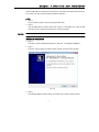
e-Link Activation
The e-link must be registered when first used. Click on the About HT-IDE3000 options in
the Help menu and a dialog box will be displayed as shown:
Fig 3-29
Click on the Register e-Link button and a dialog box will be displayed as follows:
43
Chapter 3 Menu – File/Edit/View/Tools/Option
Fig 3-30
44
Chapter 3 Menu – File/Edit/View/Tools/Option
Click on the Register Now button, a dialog box will be displayed as follows:
Fig 3-31
Fill out the register information. The e-Mail field is required, the others are optional fields.
After filling out the fields, click on the Register button and you will receive an e-mail in
your mailbox after a short time. The message header is e-Writer Pro Registry Key. Fill in
the Registration Code field and click on the Active button. The following message will be
displayed which represent a successful register process.
Fig 3-32
45
Chapter 3 Menu – File/Edit/View/Tools/Option
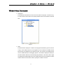
Bookmarks
The Bookmark window is a useful companion tool for the Code Editor. Lines in the user code can be
marked with bookmarks. This enables the user to open files and navigate directly to the lines marked simply
by double- clicking entries in the Bookmark window.
Bookmarks Window
The Bookmark window can be selected from the Window menu
Fig3-33
Bookmarks
Displays the name of the bookmark. Default names are created as Untitled. Custom bookmark
names can be created by double-clicking on the bookmark name entry.
Each bookmark has its own check box. To activate an existing bookmark, select its check box in
the Bookmarks window. To hide, but not remove, an existing bookmark, clear its check box in
the Bookmarks window.
File Location
Lists the fully qualified path for the file.
Line Number
Lists the line code numbers where the bookmarks are located.
Tip: Double clicking on the file location or line number will open the file and navigate directly to the marked
lines.
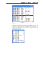
Bookmark Window Toolbar
47
Chapter 3 Menu – File/Edit/View/Tools/Option
Fig3-34
Toolbars from left to right are:
Toggle a bookmark on the current line
Adds or removes a bookmark on the selected line of the document in the active Editor. Does not
alter the code line bookmarked.
Move the indicator to the previous bookmark
Selects the previous enabled bookmark in the Bookmark window. When the first bookmark is
reached, it jumps ahead to the last one. As required, it opens the file where the selected
bookmark occurs in the Editor. Scrolls that document to the bookmarked line and places the
insertion point there.
Move the indicator to the next bookmark
Selects the next bookmark that is enabled in the Bookmark window. When the last bookmark is
reached, it jumps back to the first one. As required, it opens the file where the selected
bookmark occurs in the Editor. Scrolls that document to the bookmarked line, and places the
insertion point there.
Move the indicator to the previous bookmark in the current file
Selects the previous bookmark that is enabled within the current file in the Bookmark window.
When the first bookmark is reached, it jumps ahead to the last one in the current file. As required,
it opens the file where the selected bookmark occurs in the Editor. Scrolls that document to the
bookmarked line, and places the insertion point there.
Move the indicator to the next bookmark in the current folder
Selects the next bookmark that is enabled within the current file in the Bookmark window. When
the last bookmark is reached, it jumps back to the first one in the current file. As required, it
opens the file where the selected bookmark occurs in the Editor. Scrolls that document to the
bookmarked line, and places the insertion point there.
Clear all bookmarks
Clears all bookmarks in the Bookmarks window. Does not alter the bookmarked line code..
Bookmark menu
In addition to using the Bookmarks in the Toolbar, the same operation can be executed using the
Bookmarks Menu.
The menu can be found in the edit drop-down menu
48
Chapter 3 Menu – File/Edit/View/Tools/Option
Fig 3-35
49
Chapter 4 Menu – Project
Chapter4
Menu - Project & Build
4
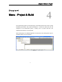
The HT-IDE3000 provides an example Project, which will assist first time users in quickly
familiarizing themselves with project development. It should be noted that from the
standpoint of the HT-IDE3000 system, a working unit is a project with each user
application described by a unique project.
When developing an HT-IDE3000 application for the first time, the development steps, as
described earlier, are recommended.
Fig 4-1
51
Chapter 4 Menu – Project
Create a New Project
In the Project menu (Fig 4-1), select the New command to create a new project. This
command will call the CodeWizard to assist users to create a new project.
Note: The project name is a file name with the extension .PJT and .PJTX.
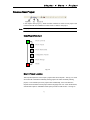
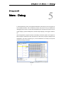
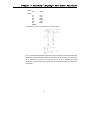
CodeWizard flowchart
Project Location
Project Option
Project Deployment
Configuration Options
Project Settings
Finish
Fig 4-2
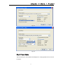
Step1: Project Location
This step will require the user to input a project name and a file path – see Fig 4-3. Users
can access all of the data and already existing projects to select an already existing
project, or can instead input a new project name. Additionally, users can select the
required microcontroller for their project and the lauguage tools. For some certain MCUs,
a BootLoader option is available and this option provides an IAP function - see Fig 4-4.
52
Chapter 4 Menu – Project
Fig 4-3
Fig 4-4
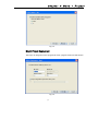
Step2: Project Option
The second step is to select whether assembly files or C-language files are to be used in
the project.
53
Chapter 4 Menu – Project
Fig 4-5
Step3: Project Deployment
This step is to change the source program File name, program section and data section.
Fig 4-6
54
Chapter 4 Menu – Project
And finally is the Configuration Option and Project Setting operations. For this consult the
related chapters.
Open and Close a Project
The HT-IDE3000 can work with only one project at a time, which is the opening project, at
any time. If a project is to be worked upon, the project should first be opened, by using the
Open command of the Project menu (Fig 4-1). Then, insert the project name directly or
browse the directories and select a project name. Use the Close command to close the
project.
Note: When opening a project, the current project is closed automatically. Within the
development period, i.e. during editing, setting options and debugging etc., ensure that
the project is in the open state. This is shown by the displaying of the project name of the
opening project on the title of the HT-IDE3000 window. Otherwise, the results are
unpredictable. The HT-IDE3000 will retain the opening project information if the system
exits from the HT-IDE3000 without closing the opening project. This project will be
opened automatically the next time the HT-IDE3000 is run.
Manage the Source Files of a Project
Use the Edit command to add or remove source program files from the opened project.
The order, from top to bottom, of each source file in the list box, is the order of the input
files to the Cross Linker. The Cross Linker processes the input files according to the order
of these files in the box. Two buttons, namely [Move Up] and [Move Down], can be used
to adjust the order of a source file in the project. Fig 4-7 is the dialog box of the Project
menu's Edit command.
55
Chapter 4 Menu – Project
Fig 4-7
To Add a Source File to the Project
Choose a source file name from the file list box. Double-click the selected file name or
choose the Add button to add the source files to the project. When the selected source file
has been added, This file name is displayed on the list box of the Files in project.
To Delete a Source File from the Project
Choose the file to be deleted from the project
Click the Delete button
Note: Deleting the source files from the project does not actually delete the file but refers to the
removal of the file information from the project.
To Move a Source File Up or Down
Choose the file to be moved in the list box (Files in project), by moving the cursor to
this file and clicking the mouse button
Click the [Move Up] button or the [Move Down] button
56
Chapter 4 Menu – Project
Build a Project’s Task Files
Be sure that the following tasks have been completed before building a new project:
The project has been opened
The project options have all been set
The project source files have been added
The MCU options have been set (refer to the Tools menu chapter)
There are two commands related to the building of a project file, the Build command and
the Rebuild all command.
The Project menu’s Build command performs the following operations:
Assemble or compile all the source files of the current project, by calling the Cross
Assembler or C compiler depends on the file extension .asm or .C
Link all the object files generated by the Cross Assembler or C compiler, and generate
a task file and a debugging file.
Load the task file into the ICE if it is powered-on
Display the source program of the execution entry point on the active window (the
HT-IDE3000 refers to the source files, the task file and the debugging file for
emulation)
Note: The Build command may or may not execute the above tasks as the execution is
dependent on the creation date/time of all corresponding files. The rules are:
If the creation date/time of a source file is later than that of its object file, then the
Cross Assembler or C compiler is called to assemble, compile this source file and to
generate a new object file.
If one of the tasks object files has a later creation date/time than that of the task file,
then the Cross Linker is called to link all object files of this task and to generate a new
task file.
The Build command downloads the task file into the ICE automatically whether there is an
action or not.
The Rebuild All command carries out the same task as the Build command. The
difference is that the Rebuild All command will execute the task immediately without first
checking the creation date/time of the project files.
The result message of executing a Build or Rebuild All command are displayed on the
57
Chapter 4 Menu – Project
Output window. If an error occurs in the processing procedure, the actions following it are
skipped, and no task file is generated, and no download is performed.
To Build a Project Task File
Click the Open command of the Project menu to open the project
Click either the Build command of the Build menu or the Build button on the toolbar
(Fig 4-1) to start building a project
To Rebuild a Project Task File
Click the Open command of the Project menu to open the project
Click either the Rebuild All command of the Project menu or the Rebuild all button
on the toolbar (Fig 4-1) to start building a project once the project task has been built
successfully, emulation and debugging of the application program can begin (refer to the
HT-IDE3000 menu - Debug chapter).
Assemble/Compile
To verify the integrity of application programs, this command can be used to assemble or
compile the source code and display the result message in the Output window.
To Assemble or Compile a Program
Use the File menu to open the source program file to be assembled or compiled
Either select the Assemble/Compile command of the Build menu or click the
Assemble button on the toolbar to assemble/compile this program file
If the opened file has an .asm file extension name, the Cross Assembler will execute the
assembly process. If the file has a .C extension then the C compiler will compile the
program.
If no errors are detected, an object file with extension .OBJ is generated and stored in the
directory which is specified in the Output Files Path (refer to Options menu, Directories
command). If an error occurs and a corresponding message displayed on the Output
window, one of the following commands can be used to move the cursor to the error line:
Double-click the left button of the mouse or
Select the error message line on the Output window, and press the <Enter> key
58
Chapter 4 Menu – Project
Print Option Table Command
This command is used to view and check the files (otp, mtp, pnd, cod) in the project (Fig
4-8). The Browse button is used to open the files. The Print button is used to print the
current active option file to the specified printer. The printer may be selected when the
option file is to be printed out. It is recommended to use a different printer port from the
port which is connected to the ICE.
If both the printer and the ICE are using the same printer port, issuing this command will
cause the loss of all debug information and corresponding data. After the printing job has
finished, the user should proceed to the very beginning of the development procedure
and use the Build command of the Project menu if further emulation/debugging of the
application program is required.
Fig 4-8
59
Chapter 4 Menu – Project
Backup/Restore Project
The Backup Project command will use PROJECT_DATE_VERSION format to compress
the current project, and also allow users to add some project description in [Description]
editing box if necessary.
The Restroe Project command will restore the compressed project which selected in the
backup list box currently.
60
Chapter 4 Menu – Project
61
Chapter
5
Menu
–
Debug
Chapter5
5
Menu - Debug
In the development process, the repeated modification and testing of source programs is
an inevitable procedure. The HT-IDE3000 provides many tools not only to facilitate the
debugging work, but also to reduce the development time. Included are functions such as
single stepping, symbolic breakpoints, automatic single stepping, trace trigger conditions,
etc.
After the application program has been successfully constructed, (refer to the chapter on
Build a project’s task files) the first execution line of the source program is displayed and
highlighted in the active window (Fig 5-1). The HT-IDE3000 is now ready to accept and
execute the debug commands.
Fig 5-1
63
Chapter
5
Menu
–
Debug
Reset the HT-IDE3000 System
There are 4 kinds of reset methods in the HT-IDE3000 system:
Power-on reset (POR) by plugging in the power adapter or pressing the reset button
on the ICE
Reset from the target board
Software reset command in the HT-IDE3000 Debug menu (Fig 5-2)
Software power-on reset command in the HT-IDE3000 Debug menu (Fig 5-2)
Fig 5-2
64
Chapter
5
Menu
–
Debug
The effects of the above 4 types of reset are listed in table 5-1.
Target
Software
Software
Board
Reset
Power-On
Reset
Command
Reset Command
(*)
(*)
(*)
(*)
Clear Options
Yes
No
No
No
Clear PD,TO
Yes
No
No
Yes
PC Value
(**)
0
0
0
Emulation Stop
(**)
No(***)
Yes
Yes
Check Stand-Alone
Yes
No
No
No
Reset Item
Power-On
Clear Registers
Reset
Table 5-1
Note: (*):Refer to the Data Book of the corresponding MCU for the effects of registers under the
different resets.
(**):The PC value is 0 and the emulation stops.
(***):If the reset is from the target board, the MCU will start emulating the application after
the reset is completed.
PC - Program Counter
PDF - Power Down Flag
TO - Time-out Flag
To Reset from the HT-IDE3000 Commands
Either choose the Reset command from Debug menu or click the Reset button on the
toolbar to execute a software reset
Either choose the Power-on Reset command from the Debug menu or click the
Power-on Reset button to execute a software power on reset
Emulation of Application Programs
After the application program has been successfully written, the Build or Rebuild
command should be executed to build the project files and download the programs to the
hardware simulator. If successful, the first executable line of the source program will be
displayed and highlighted on the active window (Fig 5-1). At this point, emulation of the
65
Chapter
5
Menu
–
Debug
application program can begin by using the HT-IDE3000 debug commands.
Note: During emulation of an application program, the corresponding project has to be open.
To Emulate the Application Program
Choose the Go command from the Debug menu
or press the hot key F5
or press the Go button on the toolbar
Other windows can be activated during emulation. The HT-IDE3000 system will
automatically stop the emulation if a break condition is met. Otherwise, it will continue
emulating until the end of the application program. The Stop button on the toolbar is
illuminated with a red color while the ICE is in emulation. Pressing this button will stop the
emulation process.
To Stop Emulating the Application Program
There are three methods to stop the emulation, shown as follows:
Set the breakpoints before starting the emulation
Choose the Stop command of the Debug menu or press the hot key Alt+F5
Press the Stop button on the toolbar
To Run the Application Program to a Line
The emulation may be stopped at a specified line when debugging a program. The
following methods provide this function. All instructions between the current point and the
specified line will be executed except the conditional skips. Note however that the
program may not stop at the specified line due to conditional jumps or other situations.
Move the cursor to the stopped line (or highlight this line)
Choose the Go to Cursor command of the Debug menu
or press the hot key F7
or press the Go to Cursor button on the toolbar
To Directly Jump to a Line of an Application Program
It is possible to jump directly to a line, if the result of executed instructions between the
current point and the specified line are not important. This command will not change the
contents of Data Memory, registers and status except for the Program Counter. The
specified line is the next line to be executed.
66
Chapter
5
Menu
–
Debug
Move the cursor to the appropriate line or highlight this line
Choose Jump to Cursor command of the Debug menu
Single Step
The execution results of some instructions in the above section may be viewed and
checked. It is also possible to view the execution results one instruction at a time, i.e., in a
step-by-step manner. The HT-IDE3000 provides two step modes, namely manual mode
and automatic mode.
In the manual mode, the HT-IDE3000 executes exactly one step command each time the
single- step command is executed. In the automatic mode, the HT-IDE3000 executes
single step commands continuously until the emulation stop command is issued, using
the Stop command of the Debug menu. In the automatic mode, all user specified
breakpoints are discarded and the step rate can be set from FAST, 0.5, 1, 2, 3, 4 to 5
seconds. There are 3 step commands, namely Step Into, Step Over and Step Out.
The Step Into command executes exactly one instruction at a time, however, it will
enter the procedure and stop at the first instruction of the procedure when it
encounters a CALL procedure instruction.
The Step Over command executes exactly one instruction at a time, however upon
encountering a CALL procedure, will stop at the next instruction after the CALL
instruction instead of entering the procedure. All instructions of this procedure will
have been executed and the register contents and status may have changed.
The Step Out command is only used when inside a procedure. It executes all
instructions between the current point and the RET instruction (including RET), and
stops at the next instruction after the CALL instruction.
To start Step Into
Choose the Step Into command from the Debug menu
or press the hot key F8
or press the Step Into button on the toolbar
To start Step Over
Choose the Step Over command of the Debug menu
or press the hot key F10
or press the Step Over button on the toolbar
67
Chapter
5
Menu
–
Debug
To start Step Out
Choose the Step Out command of the Debug menu
or press the hot key Shift+F7
or press the Step Out button on the toolbar
Note: The Step Out command should only be used when the current pointer is within a
procedure or otherwise unpredictable results may happen.
If entering the automatic mode, first choosing the Debug option attribute page of the
Project Settings from the Options menu to set the two step commands, Step Into or Step
Over in the automatic mode.
To start automatic single step mode
Choose the Stepping command from the Debug menu also choose the stepping
speed (the step command is set in the Debug command from the Options menu)
To end automatic single step mode
Choose the Stop command from the Debug menu
To change automatic single step command for the automatic mode
Choose the Project Settings command from the Options menu
Choose the Step Into or the Step Over command in the Debug option attribute
page of the Project Settings dialog box
Breakpoints
The HT-IDE3000 provides a powerful breakpoint mechanism which accepts various
forms of conditioning including program address, source line number and symbolic
breakpoint, etc
Breakpoint Features
The following are the main features of the HT-IDE3000 breakpoint mechanism:
Any breakpoint will be recorded in the breakpoints list box after it is set, however this
breakpoint may not be immediately effective. It can be set to be effective later, as long
as it is not deleted, i.e.still in the breakpoints list box.
Breakpoints of address or data, in binary form with don’t-care bits, are permitted.
68
Chapter
5
Menu
–
Debug
When an instruction is set to be an effective breakpoint, the ICE will stop at this
instruction, but will not execute it, i.e. this instruction will become the next one to be
executed. Although an instruction is an effective breakpoint, the ICE may not stop at
this instruction due to execution flow or conditional skips. If an effective breakpoint is
in the Data Space (RAM), the instruction that matches this conditional breakpoint data
will always be executed. The ICE will stop at the next instruction.
Note: 1. The ICE can only have a maximum of 3 breakpoints active at the same time, while
e-ICE can enjoy up to 65536 effective breakpoints.
2. It is acceptable to set breakpoints in Free Run mode for ICE, however, e-ICE is not.
Description of Breakpoint Items
A breakpoint consists of the following descriptive items. It is not necessary to set all items,
Fig 5-3:
Fig 5-3
Space
69
Chapter
5
Menu
–
Debug
The location of the breakpoints, can be set in Program Code space, Data space or
EEData space.
Location
For the actual location of the breakpoint, there are two different methods to comfirm
the location: Address and Line number.
Line number method:
Input the file name which the location of the breakpoint belongs to. This file can be
either a.C or .ASM file. If there is no file name, then the current file will be taken as
a default.
Input the line number of the breakpoint:
For the ICE and e-ICE, multiple line settings are not allowed. They can only be set
one line at a time. Therefore only the first edit box is active and there is no need to
input the second edit box. For the e-Link, if setting one line, then the second edit
box does not need to be filled out. If setting multiple lines, the first line number and
the last line number should be written in the two edit boxes respectively.
In addition to the line number, the symbol name is also allowed to input to the first
edit box.
When it is Code Space, the allowed symbols are as follows:
Label name. If programming in C language, the label name is a name in the .ASM
file.
Section name
Procedure name, which is the function name. If programming in C language, the
procedure name is the name in the .ASM file.
When it is Data Space, the allowed symbols are as follows:
Dynamic data symbols defined in data section. If programming in C language, the
name is a name in the .ASM file and must be a global variable.
Address method:
In this mode, only the address is needed.
When it is Code Space, this address is an address in Program.
When it is Data Space, this address is an address in RAM.
When it is EEData Space, this address is EEPROM address.
Content
The data content of the breakpoint. This item is effective only when the Space is
assigned to the Data space. The Read and Write check box are used for the
executing conditions of the breakpoint.
70
Chapter
5
Menu
–
Debug
Breakpoints
The Breakpoints list box contains all the breakpoints that have been added, including
the effective breakpoints and non-effective breakpoints. The Add button should be
used to add new breakpoints to the list box and the Delete button is to remove
breakpoints from the list box.
Event
Only the e-Link supports events. When the checked events occur, the e-Link will stop.
Note: The breakpoint in data space is only available for ICE but e-ICE.
Format of Description Items – Location
The allowed formats of Location items are:
Absolute address (in code space or data space) with 4 format types, namely decimal,
hexadecimal (suffix with “H” or “h” or prefix with 0x), binary and don’t-care bits. For
example
20, 14h , 0x14, 00010100b , 10xx0011
represents decimal 20, hexadecimal 14h/0x14, binary 00010100b and don't-care bits
4 and 5 respectively.
Note: Don’t-care bits must be in binary format.
Format of Description Items – Content
The content format has five digital number options, similar to the format of Location.
These four types of number are decimal, hexadecimal (suffix with “H” or “h”), binary and
don’t-care bits.
How to Set Breakpoints
There are four methods to set/enable a breakpoint, one is by using the Breakpoint
command from the Debug menu, the others are by using the Toggle Breakpoint button on
the toolbar, double clicking on the gray bar in the edit window, or pressing key F9. The
rules of the breakpoint mechanism are as follows:
If the breakpoint to be set is not in the Breakpoints list box (Fig 5-3), then the
descriptive items must be designated first, then added to the Breakpoints list box.
71
Chapter
5
Menu
–
Debug
As long as the breakpoint exists in the list box, it can be made effective by Enabling
the breakpoint if it fails to be initially effective.
Press the OK button for confirmation. Otherwise, all changes here will not be effective.
When using the Toggle Breakpoint button on the toolbar, the cursor should first be
moved to the breakpoint line, and then the Toggle Breakpoint button pressed. If an
effective breakpoint is to be changed to a non-effective breakpoint, this can be
achieved by merely pressing the Toggle breakpoint button.
To Add a Breakpoint
Choose the Breakpoint command from the Debug menu (or press the hot key Ctrl+B)
A breakpoint dialog box is displayed (Fig 5-3)
Designate the descriptive items of the breakpoint
Set Space, Location items
Set Content item and Read/Write check box if Space is the data space
Press the Add button to add this breakpoint to the Breakpoints list box.
Press the OK button to confirm
Note: If the total count of the effective breakpoints is less than 3, the newly added one will take
effect automatically after it has been added.
To Delete a Breakpoint
Choose the Breakpoint command from the Debug menu or press the hot key Ctrl+B
A breakpoint dialog box is displayed (Fig 5-3)
Choose or highlight the breakpoint to be deleted from the Breakpoints list box
Press the Delete button to delete this breakpoint from the Breakpoints list box
Press the OK button to confirm
To Delete all Breakpoints
Choose the Breakpoint command from the Debug menu or press the hot key Ctrl+B
A breakpoint dialog box is displayed (Fig 5-3)
Choose the Clear All button to delete all breakpoints from the Breakpoints list box
Press the OK button to confirm
You can also click the Clear All Breakpoint button on the toolbar to accomplish this
72
Chapter
5
Menu
–
Debug
task.
To Enable (Disable) a Breakpoint
Choose the Breakpoint command from the Debug menu or press the hot key Ctrl+B
A breakpoint dialog box is displayed (Fig 5-3)
Choose the disabled (enabled) breakpoint from the Breakpoints list box
Press the Enable (Disable) button, to enable or disable this breakpoint
Press the OK button to confirm
Trace the Application Program
The HT-IDE3000 provides a powerful trace mechanism which records the execution
processes and all relative information when the HT-IDE3000 is emulating the application
program. The trace mechanism provides qualifiers to filter specified instructions and
trigger conditions in order to stop the trace recording. It also provides a method to record
a specified count of the trace records before or after a trigger point.
Note: When the HT-IDE3000 starts emulating (refer to the section on Emulation of the
Application Programs), the trace mechanism will begin to record the executing
instructions and relative information automatically, but not vice versa.
Note: Only the ICE supports the trace mechanism function. The e-ICE and OCDS do not support
this function.
Initiating the Trace Mechanism
The basic requirement for initializing the trace mechanism is to set the Trace Mode with
or without Qualify. The Trace Mode defines the trace scope of the application program
and Qualify defines the filter conditions of the trace recording.
The available Trace Modes are:
Normal
Sets the trace scope to all application programs and is the default mode.
Trace Main
73
Chapter
5
Menu
–
Debug
Sets the trace scope to all application programs except the interrupt service routine
programs.
Trace INT
Sets the trace scope to all interrupt service routine programs.
According to Qualify, the trace mechanism decides which instructions and what
corresponding information should be recorded in the trace buffer during the emulation
process. The rule is that an instruction will be recorded if its information and status satisfy
one of the enabled qualifiers. If all the program steps are required to be recorded, then No
Qualify is needed (do not set the Qualify). The default is No Qualify.
Qualify format
[source_file_name!].line_number
where the source_file_name is a name of the optional source file. If there is no file
name, the current active file is assumed. The exclamation point "!" is necessary only
when a source file name is specified. The dot . must prefix the line number which is
decimal.
For example:
C:\HIDE\USER\GE.ASM!.42
Only the code executed at the 42nd line of the file GE.ASM is recorded.
For example:
.48
Only the code executed at the 48nd line of the current active file is recorded.
[source_file_name!].symbol_name
All are the same as the line number location format except that the line_number is
replaced with symbol_name. The following program symbols are acceptable:
Label name
Section name
Procedure name
Dynamic data symbols defined in data section
In contrast to the Trace Mode and Qualify, which specify the conditions of trace recording,
both the Trigger Mode and Forward Rate specify the conditions to stop the trace
recording.
The Trigger Mode specifies the kind of the stop trace trigger point, and is a standard used
74
Chapter
5
Menu
–
Debug
to determine the location of the stop trace point. The Forward Rate specifies the trace
scope between the trigger point and the stop trace point.
The available Trigger Modes are:
No Trigger
No stopping of the trace recording condition. This is the default case.
Trigger at Condition A
The trigger point is at condition A.
Trigger at Condition B
The trigger point is at condition B.
Trigger at Condition A or B
The trigger point is at either condition A or condition B.
Trigger at Condition B after A
The trigger point is at condition B after condition A has occurred.
Trigger when meeting condition A for k times
The trigger point is when condition A has occurred k times.
Trigger at Condition B after meeting A for k times
The trigger point is at condition B after condition A has occurred for k times.
Condition A and Condition B specify the trigger conditions. The format of condition A or
B is the same as that of the Qualify.
The Loop Count specifies the number of occurrences of the specified condition A. It is
used only when the Trigger Mode is from one of the last two modes in the above list.
The Forward Rate specifies the approximate rate of the trace recording information
between the trigger point and stop trace point in the whole trace buffer. The trigger point
divides the trace buffer into two parts, before and after trigger point. The forward rate is
used to limit the trace recording scope after the trigger point. The percentage is
adjustable between 0 and 100%.
Note: It is not necessary for the trace recording scope to be equal to the forward rate. If a
breakpoint is met before reaching the trace recording scope or a trace stop command
(refer to: Stopping the trace mechanism) is issued, the trace recording will be stopped.
A Qualify list box records and displays all qualifiers used by the Trace Mode. Up to 20
qualifiers can be added into the list box and and up to 6 qualifiers can be effective. A
75
Chapter
5
Menu
–
Debug
Qualifier can be disabled or deleted from the list box. In the Qualify list box,
the format of the qualifier is
<status> {<space and read/write>,
<data content>, <external signal>}
<location>,
where <status> is effective status. “+” is effective (enabled) and “–” is non-effective
(disabled). <space and read/write> is the space type and operating mode. “C” is the code
space, "D/R" is the data space with read, “D/W” is the data space with write, “D/RW” is the
data space with read and write.
<location>, <data content> and <external signal> have the same data format as the input
form respectively.
Stopping the Trace Mechanism
There are 3 methods to stop the trace recording mechanism:
Set the trigger point (Trigger Mode) and Forward Rate as shown above
Set breakpoints to stop the the emulation and the trace recording.
Issue a Trace Stop command from the Debug menu (Fig 5-2) to stop the trace
recording.
Fig 5-4 lists all the requirements to use the trace mechanism. This is the result of the
Trace command from the Debug menu.
Trace Start/Stop Setup
To Set the Trace Mode
Choose the Trace command from the Debug Menu
A Trace dialog box is displayed as in Fig 5-4.
Choose a trace mode from the Trace Mode pull-down list box
Press the OK button
76
Chapter
5
Menu
Fig 5-4
To Set the Stop Trace Trigger Mode
Choose the Trace command from the Debug Menu
A Trace dialog box is displayed as in Fig 5-4.
Choose a trigger mode from the Trigger Mode pull-down list box
press the OK button
To Change the Forward Rate
Choose the Trace command from the Debug Menu
A Trace dialog box is displayed as in Fig 5-4
Use the Forward Rate scroll bar to specify the desired rate
Press the OK button
To Setup the Condition A/Condition B
Choose the Trace command of the Debug Menu
A Trace dialog box is displayed as Fig 5-4.
Press Condition A/Condition B radio button
Press the Set Condition button
A Set Qualify dialog box is displayed as in Fig 5-5.
Enter the conditional information
77
–
Debug
Chapter
5
Menu
–
Press the OK button to close the Set Condition dialog box
Press the OK button to close the Trace dialog box
Fig 5-5
To Add a Trace Qualify Condition
Choose the Trace command from the Debug Menu
A Trace dialog box is displayed as in Fig 5-4.
Press the Qualify radio button
Press the Set Qualify button
A Set Qualify dialog box is displayed as in Fig 5-5.
Enter the qualifier information
Press the OK button to close the Set Qualify dialog box
Press the Add button to add the qualifiers into the Qualify list box below
Press the OK button to close the Trace dialog box
To Delete a Trace Qualify Condition
Choose the Trace command from the Debug Menu
A Trace dialog box is displayed as in Fig 5-4.
Choose the qualify line to be deleted from the Qualify list box
Press the Delete button
Press the OK button to confirm
To Delete All Qualify Conditions
Choose the Trace command from the Debug Menu
A Trace dialog box is displayed as in Fig 5-4.
Press the Clear All button
Press the OK button to confirm
Note: If there is no qualifier, all instructions are qualified by default.
78
Debug
Chapter
5
Menu
–
Debug
To Enable (Disable) a Trace Qualify Condition
Choose the Trace command from the Debug Menu
A Trace dialog box is displayed as in Fig 5-4
Choose the disabled (enabled) qualifier line to be enabled (disabled) from the Qualify
list box
Press the Enable (disable) button
Press the OK button to confirm
Note: At most, 6 trace qualifications can be enabled at the same time. The e-ICE is limited to
the Normal Mode, the trace range is for the whole application program.
Trace Record Format
Once the trace qualify and trigger conditions have been setup, those instructions which
satisfy the qualify conditions will be recorded in the trace buffer. The trace recorded fields
may not all be displayed on the screen except for the sequence number and disassemble
instructions. These fields are dependent upon the Trace Recoord Fields settings in the
Debug option attribute page of Project Settings sub-menu from the Options menu. The
text enclosed by the parentheses are the headings shown in the Trace List command of
the Window menu. Fig 5-6 and Fig 5-7 illustrate the contents of the trace list under the
different debug options.
Fig 5-6
Sequence number (No)
For any of the trigger modes, the sequence number of a trigger point is +0. The trace
79
Chapter
5
Menu
–
Debug
records before and after the trigger point are numbered using negative and positive
line numbers respectively. If all the fields of the Trace Record Fields (the Trace
Recoord Fields settings in the Debug option attribute page of Project Settings
sub-menu in the Options menu) are selected, the result is as shown in Fig 5-7. If No
trigger mode is selected or the trigger point has not yet occurred, the sequence
number starts from -00001 and decreases 1 sequentially for the trace records (Fig
5-6).
Program count (PC)
The program count of the instruction in this trace record.
Machine code (CODE)
The machine code of this instruction.
Disassembled instruction (INSTRUCTION)
The disassembled mnemonic instruction is disassembled using an HT-IDE3000 utility.
Execution data (DAT)
The data content to be executed (read/write).
Source file name with a line number (FILE-LINE)
The source file name and the line number of this instruction.
Source file (SOURCE)
The source line statement (including symbols).
All the above fields are optional except the sequence number which is always displayed.
Fig 5-7
80
Chapter
5
Menu
–
Debug
Note: To set the trace record fields by modifying the Trace Recoord Fields settings in the Debug
option attribute page of Project Settings sub-menu in the Options menu.
To view the trace record fields use Trace List command of the Window menu.
Clear the Trace Buffer
The trace buffer can be cleared by issuing the Reset Trace command. Hereafter, the
trace information will be saved from the beginning of the trace buffer. Note that both the
Reset command and the Power-On Reset command also clear the trace buffer.
81
Chapter 6 Menu – Window
Chapter6
6
Menu - Window
The HT-IDE3000 provides various kinds of windows which assist the user to emulate or
simulate application programs. These windows (as shown in Fig 6-1) include program
Data Memory (RAM), program code memory (ROM), Trace List, Register,Watch , Stack,
Program, Output, etc.
Fig 6-1
83
Chapter
6
Menu
–
Window
Window Menu Commands
Workspace
The Workspace window lists out all of the source files in the project. As shown in Fig.
6-2, here chosen source files can be quickly selected. Files can be added or removed
here.
Fig 6-2
RAM
The RAM window display the contents of the program Data Memory space as shown
in Fig 6-3 The address spaces of the registers are not included in the RAM window
because they are displayed in the register window. The contents of the RAM window
can be modified directly for debugging purpose. The address displayed vertically is
the base address while the horizontal single digit address is the offset. All the digits
are displayed in hexadecimal format. The Address field can input an address for direct
location and the Column filed is used to specify the number of columns.
84
Chapter
6
Menu
–
Window
Fig 6-3
ROM
The ROM window displays the contents of the program code memory space as shown
in Fig 6-4. The ROM address range is from 0 to last address where the last address
depends upon the MCU selected in the project. The horizontal and vertical scrollbars
can be used to view any address in the ROM window. The contents in ROM window
are displayed in hexadecimal format and cannot be modified.
Fig 6-4
Trace List
The Trace List window displays the trace record information as shown in Fig 6-5. The
85
Chapter
6
Menu
–
Window
contents of the trace record can be defined in the Debug command in the Options
menu. Double click the trace record in the Trace List window will activate the source
file window and the cursor will stop at the corresponding line.
86
Chapter
6
Menu
–
Window
Fig 6-5
Register
The Register window displays all the registers defined in the MCU selected in the
project. Fig 6-6 shows an example of the Register window of HT48C70-1. The
contents of the Register window can be modified for debugging. Note that the
Register window is dockable.
Fig 6-6
87
Chapter
6
Menu
–
Window
Watch
The Watch window displays the memory addresses and contents of the specified
symbols defined in the data sections, i.e., in the RAM space.
The contents of the registers can also be displayed by typing the symbol name or
register name and then pressing the Enter key. The memory address and contents
of the specified symbol or register will be displayed to the right of the symbol.
Display the specified symbol that belongs to the RAM or ROM space.
Address is displayed in hexadecimal format, and data is displayed in decimal,
hexadecimal or binary format as shown in Fig 6-7. The symbol and their
corresponding data will be saved by the HT-IDE3000 and displayed the next time
the Watch window is opened. The symbols can be deleted from Watch window by
pressing the delete key. Note that the Watch window is dockable.
Fig 6-7
Stack
The Stack window displays the contents of the stack buffer for the MCU selected in
the current project. The maximum stack level is dependent upon the MCU selected.
Fig 6-8 shows an example of the Stack window. The growth of the stack is numbered
from 0. The number is increased by 1 for a push operation (CALL instruction or
interrupt) and decreased by 1 for a pop operation (RET or RETI instructions). The top
stack line is highlighted. E.g. The 01: shown in Fig 6-8 is the top stack line. While
executing a RET or RETI instruction, the program line number specified in the top
stack line (134 in this example) will be used as the next instruction line to be executed.
Also, the line above the top stack line (00: in this example) will be used as the new top
stack line. If there is no stack line anymore, no line in the Stack window will be
highlighted. The format of the stack line is:
88
Chapter
6
Menu
–
Window
Stack_level: program_counter source_file_name(line_number)
where the stack_level is the level number of the stack, program_counter is the
hexadecimal return address of the calling procedure or the program address of the
interrupted instruction, source_file_name is the complete name of the source file
containing the calling or interrupted instruction, and line_number is the decimal line
number of the instruction after the call instruction or interrupted instruction in the
source file.
Fig 6-8
Variable
This window can view and modify variable values, including two tabs:
- Auto tab, this tab can observe and set both local variables and global variables
related to the current function.
- Local tab, this tab can observe and set local variables related to the current function.
Fig 6-9
Program
89
Chapter
6
Menu
–
Window
The Program window displays the program code memory or ROM in disassembly
format. The address range is from 0 to last address where the last address depends
upon the MCU selected in the project.
Disassembly
The Disassembly Window shows mixed high-level source code and its associated
assembler code. Each instruction is marked with code coverage indicators that show
execution status.
Fig 6-10
Output
The Output window shows the system messages from the HT-IDE3000 when the
Build/Rebuild All commands are executing. By double clicking on the error message
line, the window containing the source file will be displayed and the corresponding line
containing the error highlighted.
The Output window also displays the Program Checksum and the Program Verify
Code. This can assist the user to know if the program has been modified
90
Chapter 6 Menu – Window
91
Part II Development Language and Tools
PartII
Development Language and Tools
93
Part II
Development Language and Tools
94
Chapter 7 Assembly Language and Cross Assembler
Chapter7
Assembly Language and
Cross Assembler
7
Assembly-Language programs are written as source files. They can be assembled into
object files by the
Cross Assembler. Object files are combined by the Cross Linker to
generate a task file.
A source program is made up of statements and look up tables, giving directions to the
Cross Assembler at assembly time or to the processor at run time. Statements are
constituted by mnemonics (operations), operands and comments.
Notational Conventions
The following list describes the notations used by this document.
Example of convention
Description of convention
Syntax elements that are enclosed by a pair of brackets are
optional. For example, the syntax of the command line is as
follows:
[optional items]
HASM [options] filename [;]
In the above command line, options and semicolon; are
both optional, but filename is required, except for the
following case:
95
Chapter 7 Assembly Language and Cross Assembler
Brackets in the instruction operands. In this case, the
brackets refer to memory address.
Braces and vertical bars stand for a choice between two or
{choice1 | choice2}
more items. Braces enclose the choices whereas vertical
bars separate the choices. Only one item can be chosen.
Three dots following an item signify that more items with
the same form may be entered. For example, the directive
PUBLIC has the following form:
PUBLIC name1 [,name2 [,…]]
Repeating elements…
In the above form, the three dots following name2 indicate
that many names can be entered as long as each is
preceded by a comma.
Statement Syntax
The construction of each statement is as follows:
[name][operation][operands][;comment]
All fields are optional.
Each field (except the comment field) must be separated from other fields by at least
one space or one tab character.
Fields are not case-sensitive, i.e., lower-case characters are changed to upper-case
characters before processing.
Name
Statements can be assigned labels to enable easy access by other statements. A name
consists of the following characters:
A~Z
a~z
0~9
?
╴ @
with the following restrictions :
0~9 cannot be the first character of a name
96
Chapter 7 Assembly Language and Cross Assembler
? cannot stand alone as a name
Only the first 31 characters are recognized
Operation
The operation defines the statement action of which two types exist, directives and
instructions. Directives give directions to the Cross Assembler, specifying the manner in
which the Cross Assembler is to generate the object code at assembly time. Instructions,
on the other hand, give directions to the processor. They are translated to object code at
assembly time, the object code in turn controls the behavior of the processor at run time.
Operand
Operands define the data used by directives and instructions. They can be made up of
symbols, constants, expressions and registers.
Comment
Comments are the descriptions of codes. They are used for documentation only and are
ignored by the Cross Assembler. Any text following a semicolon is considered a
comment.
Assembly Directives
Directives give direction to the Cross Assembler, specifying the manner in which the
Cross Assembler generates object code at assembly time. Directives can be further
classified according to their behavior as described below.
Conditional Assembly Directives
The conditional block has the following form:
IF
statements
[ELSE
statements]
ENDIF
Syntax
IF expression
IFE expression
97
Chapter 7 Assembly Language and Cross Assembler
Description
The directives IF and IFE test the expression following them.
The IF directive grants assembly if the value of the expression is true, i.e. non-zero.
The IFE directive grants assembly if the value of the expression is false, i.e. zero.
Example
IF
ENDIF
debugcase
ACC1
extern
equ 5
username: byte
In this example, the value of the variable ACC1 is set to 5 and the username is
declared as an external variable if the symbol debugcase is evaluated as true, i.e.
nonzero.
Syntax
IFDEF name
IFNDEF name
Description
The directives IFDEF and IFNDEF test whether or not the given name has been
defined. The IFDEF directive grants assembly only if the name is a label, a variable or
a symbol. The IFNDEF directive grants assembly only if the name has not yet been
defined. The conditional assembly directives support a nesting structure, with a
maximum nesting level of 7.
Example
IFDEF
buf_flag
buffer DB 20 dup (?)
ENDIF
In this example, the buffer is allocated only if the buf_flag has been previously defined.
File Control Directives
Syntax
INCLUDE
or
INCLUDE
file-name
-
Description
This directive inserts source codes from the source file given by file-name into the
current source file during assembly. Cross Assembler supports at most 7 nesting
levels.
Example
INCLUDE
macro.def
In this example, the Cross Assembler inserts the source codes from the file macro.def
98
Chapter 7 Assembly Language and Cross Assembler
into the current source file.
Syntax
PAGE size
Description
This directive specifies the number of the lines in a page of the program listing file.
The page size must be within the range from 10 to 255, the default page size is 60.
Example
PAGE 57
This example sets the maximum page size of the listing file to 57 lines.
Syntax
.LIST
.NOLIST
Description
The directives .LIST and .NOLIST decide whether or not the source program lines are
to be copied to the program listing file. .NOLIST suppresses copying of subsequent
source lines to the program listing file. .LIST restores the copying of subsequent
source lines to the program listing file. The default is .LIST.
Example
.NOLIST
mov a, 1
mov b1, a
.LIST
In this example, the two instructions in the block enclosed by .NOLIST and .LIST are
suppressed from copying to the source listing file.
Syntax
.LISTMACRO
.NOLISTMACRO
Description
The directive .LISTMACRO causes the Cross Assembler to list all the source
statements, including comments, in a macro. The directive .NOLISTMACRO
suppresses the listing of all macro expansions. The default is .NOLISTMACRO.
Syntax
.LISTINCLUDE
.NOLISTINCLUDE
Description
The directive .LISTINCLUDE inserts the contents of all included files into the program
listing. The directive .NOLISTINCLUDE suppresses the addition of included files. The
default is .NOLISTINCLUDE.
99
Chapter 7 Assembly Language and Cross Assembler
Syntax
MESSAGE ’text-string’
Description
The directive MESSAGE directs the Cross Assembler to display the text-string on the
screen. The characters in the text-string must be enclosed by a pair of single
quotation marks.
Syntax
ERRMESSAGE ’error-string’
Description
The directive ERRMESSAGE directs the Cross Assembler to issue an error. The
characters in the error-string must be enclosed by a pair of single quotation marks.
Program Directives
Syntax(comment)
; text
Description
A comment consists of characters preceded by a semicolon (;) and terminated by an
embedded carriage-return/line-feed.
Syntax
name .SECTION [align] [combine] ‘class’
Description
The .SECTION directive marks the beginning of a program section. A program section
is a collection of instructions and/or data whose addresses are relative to the section
beginning with the name which defines that section. The name of a section can be
unique or be the same as the name given to other sections in the program. Sections
with the same complete names are treated as the same section. The optional align
type defines the alignment of the given section. It can be one of the following:
BYTE
WORD
PARA
PAGE
uses any byte address (the default align type)
uses any word address
uses a paragraph address
uses a page address
For the CODE section, the byte address is in a single instruction unit. BYTE aligns the
section at any instruction address, WORD aligns the section at any even instruction
address, PARA aligns the section at any instruction address which is a multiple of 16,
and PAGE aligns the section at any instruction address with a multiple of 256.
For DATA sections, the byte address is in one byte units (8 bits/byte). BYTE aligns the
section at any byte address, WORD aligns the section at any even address, PARA
aligns the section at any address which is a multiple of 16, and PAGE aligns the
100
Chapter 7 Assembly Language and Cross Assembler
section at any address which is a multiple of 256. The optional combine type defines
the way of combining sections having the same complete name (section and class
name). It can be any one of the following:
COMMON
Creates overlapping sections by placing the start of all sections with the same
complete name at the same address. The length of the resulting area is the length
of the longest section.
AT address
Causes all label and variable addresses defined in a section to be relative to the
given address. The address can be any valid expression except a forward
reference. It is an absolute address in a specified ROM/RAM bank and must be
within the ROM/RAM range.
If no combine type is given, the section is combinative, i.e., this section can be
concatenated with all sections having the same complete name to form a single,
contiguous section. The class type defines the sections that are to be loaded in the
contiguous memory. Sections with the same class name are loaded into the memory
one after another. The class name CODE is used for sections stored in ROM, and the
class name DATA is used for sections stored in RAM. The complete name of a
section consists of a section name and a class name. The named section includes all
codes and data below (after) it until the next section is defined.
Syntax
ROMBANK banknum section-name [,section-name,...]
Description
This directive declares which sections are allocated to the specified ROM bank. The
banknum specifies the ROM bank, ranging from 0 to the maximum bank number of
the destination MCU. The section-name is the name of the section defined previously
in the program. More than one section can be declared in a bank as long as the total
size of the sections does not exceed the bank size of 8K words. If this directive is not
declared, bank 0 is assumed and all CODE sections defined in this program will be in
bank 0. If a CODE section is not declared in any ROM bank, then bank 0 is assumed.
Syntax
RAMBANK banknum section-name [,section-name,...]
Description
This directive is similar to ROMBANK except that it specifies the RAM bank, the size
of RAM bank is 256 bytes.
Syntax
END
Description
101
Chapter 7 Assembly Language and Cross Assembler
This directive marks the end of a program. Adding this directive to any included file
should be avoided.
Syntax
ORG expression
Description
This directive sets the location counter to expression. The subsequent code and data
offsets begin at the new offset specified by expression. The code or data offset is
relative to the beginning of the section where the directive ORG is defined. The
attribute of a section determines the actual value of offset, absolute or relative.
Example
ORG 8
mov A, 1
In this example, the statement mov A, 1 begins at location 8 in the current section.
Syntax
PUBLIC name1 [,name2 [,...]]
EXTERN name1:type [,name2:type [,...]]
Description
The PUBLIC directive marks the variable or label specified by a name that is available
to other modules in the program. The EXTERN directive, on the other hand, declares
an external variable, label or symbol of the specified name and type. The type can be
one of the three types: BYTE, BIT (these two types are for data variables), and NEAR
(a label type and used by call or jmp).
Example
PUBLIC start, setflag
EXTERN tmpbuf:byte
CODE
.SECTION ‘CODE‘
start:
mov
a, 55h
call
setflag
...
setflag proc
mov
tmpbuf, a
ret
setflag endp
end
In this example, both the label start and the procedure setflag are declared as public
variables. Programs in other sources may refer to these variables. The variable
tmpbuf is also declared as external. There should be a source file defining a byte that
is named tmpbuf and is declared as a public variable.
Syntax
name PROC
102
Chapter 7 Assembly Language and Cross Assembler
name ENDP
Description
The PROC and ENDP directives mark a block of code which can be called or jumped
to from other modules. The PROC creates a label name which stands for the address
of the first instruction of a procedure. The Cross Assembler will set the value of the
label to the current value of the location counter.
Example
toggle PROC
mov
mov
xorm
mov
ret
toggle ENDP
tmpbuf, a
a, 1
a, flag
a, tmpbuf
Syntax
[label:] DC expression1 [,expression2 [,...]]
Description
The DC directive stores the value of expression1, expression2 etc. in consecutive
memory locations. This directive is used for the CODE section only. The bit size of the
result value is dependent on the ROM size of the MCU. The Cross Assembler will
clear any redundant bits; expression1 has to be a value or a label. This directive may
also be employed to setup the table in the code section.
Example
table: DC
0128H, 025CH
In this example, the Cross Assembler reserves two units of ROM space and also
stores 0128H and 025CH into these two ROM units.
Data Definition Directives
An assembly language program consists of one or more statements and comments. A
statement or comment is a composition of characters, numbers, and names. The
assembly language supports integer numbers. An integer number is a collection of binary,
octal, decimal, or hexadecimal digits along with an optional radix. If no radix is given, the
Cross Assembler uses the default radix (decimal). The table lists the digits that can be
used with each radix.
Radix
Type
Digits
B
Binary
01
O
Octal
01234567
D
Decimal
0123456789
103
Chapter 7 Assembly Language and Cross Assembler
H
Hexadecimal
0123456789ABCDEF
Syntax
[name] DB value1 [,value2 [,...]]
[name] DBIT
[name] DB repeated-count DUP(?)
Description
These directives reserve the number of bytes specified by the repeated-count or
reserve bytes only. value1 and value2 should be ? due to the microcontroller RAM .
The Cross Assembler will not initialize the RAM data. DBIT reserves a bit. The
content ? denotes uninitialized data, i.e., reserves the space of the data. The Cross
Assembler will gather every 8 DBIT together and reserve a byte for these 8 DBIT
variables.
Example
DATA
.SECTION
‘DATA’
tbuf
DB ?
flag1
DBIT
sbuf
DB ?
cflag
DBIT
In this example, the Cross Assembler reserves byte location 0 for tbuf, bit 0 of location
1 for flag1, location 2 for sbuf and bit 1 of location 1 for cflag.
Syntax
name LABEL {BIT|BYTE|WORD}
Description
The name with the data type has the same address as the following data variable
Example
lab1
LABEL
WORD
d1
DB ?
d2
DB ?
In this example, d1 is the low byte of lab1 and d2 is the high byte of lab1.
Syntax
name EQU expression
Description
The EQU directive creates absolute symbols, aliases, or text symbols by assigning an
expression to name. An absolute symbol is a name standing for a 16-bit value; an
alias is a name representing another symbol; a text symbol is a name for another
combination of characters. The name must be unique, i.e. not having been defined
previously. The expression can be an integer, a string constant, an instruction
mnemonic, a constant expression, or an address expression.
Example
accreg
bmove
EQU
EQU
5
mov
104
Chapter 7 Assembly Language and Cross Assembler
In this example, the variable accreg is equal to 5, and bmove is equal to the instruction
mov.
Macro Directives
Macro directives enable a block of source statements to be named, and then that name to
be re-used in the source file to represent the statements. During assembly, the Cross
Assembler automatically replaces each occurrence of the macro name with the
statements in the macro definition.
A macro can be defined at any place in the source file as long as the definition precedes
the first source line that calls this macro. In the macro definition, the macro to be defined
may refer to other macros which have been previously defined. The Cross Assembler
supports a maximum of 7 nesting levels.
Syntax
name MACRO [dummy-parameter [,...]]
statements
ENDM
The Cross Assembler supports a directive LOCAL for the macro definition.
Syntax
name LOCAL dummy-name [,...]
Description
The LOCAL directive defines symbols available only in the defined macro. It must be
the first line following the MACRO directive, if it is present. The dummy-name is a
temporary name that is replaced by a unique name when the macro is expanded. The
Cross Assembler creates a new actual name for dummy-name each time the macro is
expanded. The actual name has the form ??digit, where digit is a hexadecimal
number within the range from 0000 to FFFF. A label should be added to the LOCAL
directive when labels are used within the MACRO/ENDM block. Otherwise, the Cross
Assembler will issue an error if this MACRO is referred to more than once in the
source file.
In the following example, tmp1 and tmp2 are both dummy parameters, and are
replaced by actual parameters when calling this macro. label1 and label2 are both
declared LOCAL, and are replaced by ??0000 and ??0001 respectively at the first
reference, if no other MACRO is referred. If no LOCAL declaration takes place, label1
and label2 will be referred to labels, similar to the declaration in the source program.
At the second reference of this macro, a multiple define error message is displayed.
Delay
MACRO
LOCAL
mov
mov
tmp1, tmp2
label1, label2
a, 70h
tmp1, a
105
Chapter 7 Assembly Language and Cross Assembler
label1:
label2:
mov
tmp2, a
clr
clr
sdz
jmp
sdz
jmp
ENDM
wdt1
wdt2
tmp2
label2
tmp1
label1
The following source program refers to the macro Delay ...
; T.ASM
; Sample program for MACRO.
.ListMacro
Delay MACRO tmp1, tmp2
LOCAL label1, label2
mov
a, 70h
mov
tmp1, a
label1:
mov
tmp2, a
label2:
clr
wdt1
clr
wdt2
sdz
tmp2
jmp
label2
sdz
tmp1
jmp
label1
ENDM
data .section 'data'
BCnt db ?
SCnt db ?
code .section at 0 'code'
Delay BCnt, SCnt
end
The Cross Assembler will expand the macro Delay as shown in the following listing file.
Note that the offset of each line in the macro body, from line 4 to line 17, is 0000. Line
24 is expanded to 11 lines and forms the macro body. In addition the formal
parameters, tmp1 and tmp2, are replaced with the actual parameters, BCnt and SCnt,
respectively.
106
Chapter 7 Assembly Language and Cross Assembler
File: T.asm
1
2
3
4
5
6
7
8
9
10
11
12
13
14
15
16
17
18
19
20
21
22
23
24
24
24
24
24
24
24
24
24
24
24
24
25
0000
0000
0000
0000
0000
0000
0000
0000
0000
0000
0000
0000
0000
0000
0000
0000
0000
0000
0000
0000
0001
0002
0000
0000
0000
0001
0002
0002
0003
0003
0004
0005
0006
0007
0008
0009
Holtek Cross-Assembler
Version 2.80
Page 1
; T.ASM
; Sample program for MACRO.
.ListMacro
Delay MACRO tmp1, tmp2
LOCAL label1, label2
mov
a, 70h
mov
tmp1, a
label1:
mov
tmp2, a
label2:
clr
wdt1
clr
wdt2
sdz
tmp2
jmp
label2
sdz
tmp1
jmp
label1
ENDM
data .section 'data'
BCnt db ?
SCnt db ?
00
00
0F70
0080
0080
0001
0005
1780
2803
1780
2802
1
R1
1
R1
1
1
1
R1
1
R1
1
code .section at 0 'code'
Delay BCnt, SCnt
mov
a, 70h
mov
BCnt, a
??0000:
mov
SCnt, a
??0001:
clr
wdt1
clr
wdt2
sdz
SCnt
jmp
??0001
sdz
BCnt
jmp
??0000
end
0 Errors
Assembly Instructions
The syntax of an instruction has the following form:
[name:] mnemonic [operand1 [,operand2] ] [; comment]
where
name:
mnemonic
operand1
→ label name
operand2
→ registers
→ instruction name (keywords)
→ registers
memory address
memory address
immediate value
Name
A name is made up of letters, digits, and special characters, and is used as a label.
107
Chapter 7 Assembly Language and Cross Assembler
Mnemonic
Mnemonic is an instruction name dependent upon the type of the MCU used in the source
program.
Operand, Operator and Expression
Operands (source or destination) are the argument defining values that are to be acted on
by instructions. They can be constants, variables, registers, expressions or keywords.
When using the instruction statements, care must be taken to select the correct operand
type, i.e. source operand or destination operand. The dollar sign $ is a special operand,
namely the current location operand.
An expression consists of many operands that are combined to describe a value or a
memory location. The combined operators are evaluated at assembly time. They can
contain constants, symbols, or any combination of constants and symbols that are
separated by arithmetic operators.
Operators specify the operations to be performed while combining the operands of an
expression. The Cross Assembler provides many operators to combine and evaluate
operands. Some operators work with integer constants, some with memory values, and
some with both. Operators handle the calculation of constant values that are known at the
assembly time. The following are some operators provided by the Cross Assembler.
Arithmetic operators + – * / %(MOD)
SHL 和 SHR operators
Syntax
expression SHR count
expression SHL count
The values of these shift bit operators are all constant values. The expression is
shifted right SHR or left SHL by the number of bits specified by count. If bits are
shifted out of position, the corresponding bits that are shifted in are zero-filled. The
following are such examples:
mov
mov
A, 01110111b
A, 01110111b
SHR 3 ; result ACC=00001110b
SHL 4 ; result ACC=01110000b
Bitwise operators NOT、AND、OR、XOR
Syntax
NOT expression
expression1
AND expression2
expression1
OR expression2
108
Chapter 7 Assembly Language and Cross Assembler
expression1
NOT
XOR expression2
is a bitwise complement.
AND
is a bitwise AND.
OR
is a bitwise inclusive OR.
XOR
is a bitwise exclusive OR.
OFFSET operator
Syntax
OFFSET expression
The OFFSET operator returns the offset address of an expression. The expression
can be a label, a variable, or other direct memory operand. The value returned by the
OFFSET operator is an immediate operand.
LOW、MID 和 HIGH operator
Syntax
LOW expression
MID expression
HIGH expression
The LOW/MID/HIGH operator returns the value of an expression if the result of the
expression is an immediate value. The LOW/MID/HIGH operators will then take the
low/middle/ high byte of this value. But if the expression is a label, the LOW/MID/HIGH
operator will take the values of the low/middle/high byte of the program count of this
label.
For example:
cs .section at 456H 'code'
lab1:
…
Then:
mov a,low 9840H mov a,40H
mov a,mid 9840H mov a,84H
mov a,high 9840H mov a,98H
mov a,low lab1 mov a,56H
mov a,mid lab1 mov a,45H
mov a,high lab1 mov a,4H
BANK operator
Syntax
BANK name
The BANK operator returns the bank number allocated to the section of the name
declared. If the name is a label then it returns the rom bank number. If the name is a
data variable then it returns the ram bank number. The format of the bank number is
the same as the BP defined. For more information of the format please refer to the
data sheets of the corresponding MCUs. (Note: The format of the BP might be
109
Chapter 7 Assembly Language and Cross Assembler
different between MCUs.)
Example 1:
mov A, BANK start
mov BP, A
jmp start
Example 2:
mov A, BANK var
mov BP, A
mov A, OFFSET var
mov MP1, A
mov A, R1
Operator precedence
Precedence
1(Highest)
2
3
4
5
6
7
8
9(Lowest)
Operators
( ), [ ]
+ , – (unary), LOW, MID, HIGH, OFFSET, BANK
*, /, %, SHL, SHR
+, – (binary)
>(greater than), >=(greater than or equal to),
<(less than), <= (less than or equal to)
= = (equal to), !=(not equal to)
! (bitwise NOT)
& (bitwise AND)
| (bitwise OR), ^ (bitwise XOR)
Miscellaneous
Forward References
The Cross Assembler allows reference to labels, variable names, and other symbols
before they are declared in the source code (forward named references). But symbols to
the right of EQU are not allowed to be forward referenced.
Local Labels
A local label is a label with a fixed form such as $number. The number can be 0~29. The
function of a local label is the same as a label except that the local label can be used
repeatedly. The local label should be used between any two consecutive labels and the
same local label name may used between other two consecutive labels. The Cross
Assembler will transfer every local label into a unique label before assembling the source
file. At most 30 local labels can be defined between two consecutive labels.
Example
Label1:
; label
110
Chapter 7 Assembly Language and Cross Assembler
$1:
$2:
$3:
Label2:
$0:
Label3:
$1:
;; local label
mov a, 1
jmp $3
;; local label
mov a, 2
jmp $1
;; local label
jmp $2
; labe1
Jmp $1
jmp Label1
jmp $0
111
;; local label
Chapter 7 Assembly Language and Cross Assembler
Reserved Assembly Language Words
The following tables list all reserved words used by the assembly language.
Reserved Names (directives, operators)
$
DUP
*
INCLUDE
NOT
LABEL
OFFSET
+
ELSE
.LIST
OR
-
END
.LISTINCLUDE
ORG
.
ENDIF
.LISTMACRO
PAGE
/
ENDM
LOCAL
PARA
=
ENDP
LOW
PROC
?
EQU
MACRO
PUBLIC
[]
ERRMESSAGE
MESSAGE
RAMBANK
AND
EXTERN
MID
ROMBANK
BANK
HIGH
MOD
.SECTION
BYTE
IF
NEAR
SHL
DB
IFDEF
.NOLIST
SHR
DBIT
IFE
.NOLISTINCLUDE
WORD
DC
IFNDEF
.NOLISTMACRO
XOR
Reserved Names (instruction mnemonics)
ADC
HALT
RLCA
SUB
ADCM
INC
RR
SUBM
ADD
INCA
RRA
SWAP
ADDM
JMP
RRC
SWAPA
AND
MOV
RRCA
SZ
ANDM
NOP
SBC
SZA
CALL
OR
SBCM
TABRDC
CLR
ORM
SDZ
TABRDL
CPL
RET
SDZA
XOR
CPLA
RETI
SET
XORM
DAA
RL
SIZ
DEC
RLA
SIZA
DECA
RLC
SNZ
Reserved Names (registers names)
A
WDT
WDT1
112
WDT2
Chapter 7 Assembly Language and Cross Assembler
Cross Assembler Options
The Cross Assembler options can be set via the Options menu Project command in
HT-IDE3000. The Cross Assembler Options is located on the center part of the Project
Option dialog box, as shown in Fig 7-1.
The symbols could be defined in the Define Symbol edit box.
Fig 7-1
Syntax
symbol1 [=value1] [,symbol2 [=value2 ] [,...]]
Example
debugflag=1, newver=3
113
Chapter 7 Assembly Language and Cross Assembler
The check box of the Generate listing file is used to decide whether the listing file
should be generated or not. If the check box is checked, the listing file will be
generated. Otherwise, it won’t be generated.
There is an assembly case sensitive check box in the Project’s Build Opion
menu. If the check box is checked, it represents case-sensitive. When
programming in different languages, this check box is checked in general. If
the check box is not checked, it is not case-sensitive.
Fig 7-2
Assembly Listing File Format
The Assembly Listing File contains the source program listing and summary information.
The first line of each page is a title line which include company name, the Cross
Assembler version number, source file name, date/time of assembly and page number.
Source Program Listing
Each line in the source program has the following syntax:
line-number offset [code] statement
Line-number is the number of the line starting from the first statement in the assembly
source file (4 decimal digits).
The 2nd field – offset – is the offset from the beginning of the current section to the
code (4 hexadecimal digits)
114
Chapter 7 Assembly Language and Cross Assembler
The 3rd field – code – is present only if the statement generates code or data (two
hexadecimal 4-digit data)
The code shows the numeric value in hexadecimal if the value is known at assembly
time. Otherwise, a proper flag will indicate the action required to compute the value.
The following two flags may appear behind the code field.
R
→ relocatable address (Cross Linker must
resolve)
E
→ external symbol (Cross Linker must resolve)
The following flag may appear before the code field
=
→ EQU or equal-sign directive
The following 2 flags may appear in the code field
----
→ section address (Cross Linker must resolve)
nn[xx] → DUP expression: nn DUP(?)
The 4th field – statement – is the source statement shown exactly as it appears in the
source file, or as expanded by a macro. The following flags may appear before a
statement.
n
→ Macro-expansion nesting level
C
→ line from INCLUDE file
Summary
0
1
2
3
4
5
6
123456789012345678901234567890123456789012345678901234567890 ...
l l l l oooo hhhh hhhh EC sou r ce -p rogram-s t a temen t
Rn
IIII → line number (4 digits, right alignment)
oooo → offset of code (4 digits)
hhhh → two 4-digits for opcode
E → external reference
C → statement from included file
R → relocatable name
n → Macro-expansion nesting level
Summary of Assembly
The total warning number and total error number is the information provided at the end of
the Cross Assembler listing file.
Miscellaneous
If any errors occur during assembly, each error message and error number will appear
directly below the statement where the error occurred.
115
Chapter 7 Assembly Language and Cross Assembler
Example of Assembly Listing File
File: SAMPLE.ASM
1
2
3
4
5
6
7
0000
0000
0000
0000
0000
0000
0000
1
2
3
4
5
6
7
0000
0000
0000
0000
0000
0000
0000
8
9
10
11
12
13
14
15
16
17
18
19
20
21
22
23
24
25
26
27
28
29
30
31
32
33
33
33
33
33
34
35
36
37
38
39
0000
0000
0000
0000
0000
0000
0000
0000
0000
0000
0000
0000
0000
0000
0000
0000
0001
0002
0003
0000
0000
0001
0002
0003
0004
0005
0005
0006
0007
0007
0008
0009
000A
000B
000C
000C
40
0010
Holtek Cross-Assembler
page 60
message
Version 2.86
'Sample Program 1'
.listinclude
.listmacro
#include "sample.inc"
C
C
C
C
C
C
C
pa
pac
pb
pbc
pc
pcc
equ
equ
equ
equ
equ
equ
[12h]
[13h]
[14h]
[15h]
[16h]
[17h]
extern extlab : near
extern extb1 : byte
clrpb macro
clr pb
endm
clrpa macro
mov a, 00h
mov pa, a
clrpb
endm
data .section 'data'
b1
db ?
b2
db ?
bit1 dbit
00
00
00
0F55
0080
0080
0FAA
0093
0F00
0092
1F14
0700
0F00
0F00
2800
1234 5678
ABCD EF12
R
E
1
1
1
2
R
E
E
E
code .section 'code'
mov a, 055h
mov b1, a
mov extb1, a
mov a, 0aah
mov pac, a
clrpa
mov a, 00h
mov [12h], a
clrpb
clr [14h]
mov a, b1
mov a, bank extlab
mov a, offset extb1
jmp extlab
dw
end
0 Errors
116
1234h, 5678h, 0abcdh, 0ef12h
Page 1
Chapter 8 Cross Linker
Chapter8
8
Cross Linker
What the Cross Linker Does
The Cross Linker creates task files from the object files generated by the Cross
Assembler or the C compiler. The Cross Linker combines both code and data in the
object files and searches the named libraries to resolve external references to routines
and variables. It also locates the code and data sections at the specified memory address
or at the default address, if no explicit address is specified. Finally, the Cross Linker
copies both the program codes and other information to the task file. It is this task file that
is loaded by the
IDE Integrated Development Environment, into the
ICE In-Circuit
Emulator, for debugging. The libraries included by the Cross Linker were generated by
the
library manager.
Cross Linker Options
The options specify and control the tasks performed by Cross Linker. In chapter 3, Option
Menu, Project command provides a dialog box, Cross Linker Options, to specify these
options to the Cross Linker. These options are:
117
Chapter
8
Cross
Linker
Fig 8-1
Libraries
Syntax
libfile1[,libfile2...]
This option informs the Cross Linker to search the specified library files if the input
object files refer to a procedure or variable which is not defined in any of the object
files. If a module of a library file contains the referred procedure or variable, then only
this module, not the whole library file will be included in the output task file. (refer to
Chapter 9 Library Manager)
Section Address
Syntax
section_name=address[,section_name=address]...
This option specifies the address of the sections; section_name is the name of the
section that is to be addressed. The section_name must be defined in at least one
input object file, otherwise a warning will occur. The address is the specified address
whose format is xxxx in hexadecimal format.
118
Chapter
8
Cross
Linker
Generate Map File
The check box of this option is to specify whether the map file is generated or not.
Linker Options
Linker options is only available for the Compiler V3.10/Assembler.
Optimize data memory:If not nesting interrupts occur in the project,select the option can
save data memory.
Remove unused function:If a function is not called, then the system will not assign space
for it, this option is enabled by default.
Uninitialized global/static varibles are automatically set to 0:If a global has no initial value,
the default initial value is 0, this value will be cleared when the program starts running.
Warn if the address of the alias variable is overlap:Check whether the address of the
alias variable is overlapping or not. If the address is address is overlapping , then a
warning will be generated.
Arrange the ROM space by address order:
linker will arrange the function in a small space
priority if not select this option.
119
Chapter
8
Cross
Linker
Fig 8-2
Map File
The map file lists the names and loads the addresses and lengths of all sections in a
program as well as listing the messages it encounters. The Cross Linker gives the
address of the program entry point at the end of the map file. The map file also lists the
names and loads addresses of all public symbols. The names and file names of the
external symbols or procedures are recorded in the map file if no corresponding public
symbol or procedure can be found. The contents of the map file are as follows :
Input Object File: C:\t\T.OBJ
Input Object File: C:\t\STARTUP1_L.OBJ
Input
Library
File:
C:\Program
Files\Holtek
Tools\HT-IDE3000V7.81\LIB\LIBHOLTEKGCC.LIB
120
MCU
Development
Chapter
8
Input
Library
File:
C:\Program
Files\Holtek
Tools\HT-IDE3000V7.81\LIB\v3_mrsc.lib
Input
Library
File:
C:\Program
Files\Holtek
Tools\HT-IDE3000V7.81\LIB\v3_tabrd_mrsc.lib
Cross
Linker
MCU
Development
MCU
Development
Bank
Start
End
Length
Class
Name
00h
0000h
0000h
0001h
CODE
@code (C:\t\T.OBJ)
00h
0001h
0001h
0001h
CODE
_main (C:\t\T.OBJ)
00h
0002h
0002h
0001h
CODE
@ROMDATA_BASE
(C:\t\STARTUP1_L.OBJ)
00h
0004h
0007h
0004h
CODE
@isr04_code (C:\t\T.OBJ)
00h
0008h
0028h
0021h
CODE
@start (C:\t\T.OBJ)
00h
0029h
0033h
000bh
CODE
_isr04 (C:\t\T.OBJ)
00h
0034h
0038h
0005h
CODE
_fun (C:\t\T.OBJ)
00h
0080h
0081h
0002h
DATA
@HCCINIT0 (C:\t\T.OBJ)
Local Sections
Bank
00h
00h
00h
00h
00h
Start
0085h
0082h
0085h
0085h
0085h
End
0085h
0084h
0085h
0085h
0085h
Length
0000h
0003h
0000h
0000h
0000h
Class
LOCAL
LOCAL
LOCAL
LOCAL
LOCAL
Name
@dummy4 (C:\t\T.OBJ)
_isr04 (C:\t\T.OBJ)
@dummy (C:\t\T.OBJ)
_main (C:\t\T.OBJ)
_fun (C:\t\T.OBJ)
Public Symbols Information
Address
Public by Name
0034h
_fun
0080h
_g_a
0029h
_isr04
0082h
_isr04fs
0001h
_main
0001h
startup_value_1
Address
0001h
0001h
0029h
0034h
0080h
0082h
Public by Value
_main
startup_value_1
_isr04
_fun
_g_a
_isr04fs
Error(L2001) : Unresolved external symbol '_g_b' in file 'C:\t\T.OBJ'
ROM Usage Statistics
Size
Used
2000h
0038h
Percentage
0%
RAM Usage Statistics
Bank
Size
Used
121
Percentage
Chapter
00h
01h
02h
Total
0080h
0080h
0080h
0180h
0005h
0000h
0000h
0005h
8
Cross
Linker
3%
0%
0%
1%
Use Stack Count
_isr04: 0
_main: 1
Call Tree
@dummy4
_isr04
@dummy
_main
_fun
Total 1 error(s), Total 0 Warning(s)
Cross Linker Task File and Debug File
One of the Cross Linker’s output files is the task file which consists of two parts, a task
header and binary code. The task header contains the Cross Linker version, the MCU
name and the ROM code size. The binary code part contains the program codes. The
other Cross Linker output file is the debug file which contains all information referred to by
the
IDE debugging program. This information includes source file names, symbol
names and line numbers as defined in the source files. The
IDE will refer to the
symbolic debugging function information. This file should not be deleted unless the
debugging procedure is completed, otherwise the
symbolic debugging function.
122
IDE will be unable to support the
Chapter
123
8
Cross
Linker
Part III Utilities
PartIII
Utilities
In addition to the previously discussed general purpose 8-bit MCU development tools, the
comapny also supplies several other utilities for its range of special purpose Voice and
LCD MCU devices by supplying all the necessary tools and step by step guide for
relevant simulation of voice synthesis and tone generator applications as well as the tools
for real time hardware LCD panel simulation. This part contains all the information
needed to program and debug relevant applications quickly and efficiently.
125
Part
126
III
Utilities
Chapter 9 Library Manager
Chapter9
9
Library Manager
What the Library Manager Does
The Library Manager provides functions to process the library files. The library files are
utilized in the creation of the output file by the Cross Linker. Alibrary is a collection of one
or more object modules which are assembled or compiled and ready for linking. It stores
the modules that other programs may require for execution.
By using the Library Manager, library files can be created. Object files including common
routines may be added to the library files. Before creating these object files, the names of
all common routines must be made public by using the assembly directive PUBLIC (refer
to the chapter on Assembly Language and Cross Assembler). The Cross Assembler
generates the output object file (.OBJ) while the Library Manager adds this object file into
the specified library file. When the Cross Linker has found unresolved names in a
program during the linking process, it will search the library files for these unresolved
names, and extracts a copy of the module containing that name. If an unresolved name
has been found in this library module, the module will be linked to the program.
To Setup the Library Files
The Library Manager provides the following functions :
Create new library files
Add/Delete a program module to/from a library file
127
Chapter
9
Library
Manager
Extract a program module from a library file, and create an object file
To select use the Tools Menu and the Library Manager command as shown in Fig 9-1.
Fig 9-2 shows the dialogue box for processing the functions of the Library Manager.
Fig 9-1
Fig 9-2
Create a New Library File
Press Open button, Fig 9-3 is displayed
128
Chapter
9
Library
Manager
Type in a new library file name and press the OK button, Fig 9-4 is displayed for
confirmation. If the Yes button is chosen, a new library file will be created but will not
contain any program modules.
Fig 9-3
Fig 9-4
Add a Program Module into a Library File
Select an object module from the “Object in Directory” box, and press the [ADD] button to
add this object module into this library file.
Delete a Program Module from a Library File
Select an object module from the “Object In Library” box, and press the [Delete] button to
delete this object module from the library file.
129
Chapter
9
Library
Manager
Extract a Program Module from Library and Create An Object File
Select an object module from the “Object in Library” box, and press [ExTract] button. A
file will then be created with the same name and same content as the selected object
module. It is displayed on the “Object in Directory” box.
Object Module Information
Press the Open button, Fig 9-3 is displayed. Select a library file from the box below the
File Name box, press OK button. From Fig 9-2, all the object modules of the selected
library file are listed in the “Object in Library” box. The following information about each
object module is also listed in the “Objects’ Information” box:
Maximum ROM size
The maximum size used by this object module program code. Dependent upon the
code section align type.
Minimum ROM size
The minimum actual size used by this object module program code
Maximum RAM size
The maximum size used by this object module program data. It depends on the data
section align type.
Minimum RAM size
The minimum, actual size used by this object module program data.
Public Name
The names of all public symbols in this object module.
130
Part IV Appendix
PartIV
Appendix
131
Appendix A Reserved Words Used By Cross Assembler
132
Appendix A Reserved Words Used By Cross Assembler
AppendixA
A
Reserved Words
Used By Cross Assembler
Reserved Assembly Language Words
The following table lists all reserved words used by the assembly language.
Reserved Names (directives, operators)
$
DUP
*
INCLUDE
NOT
LABEL
OFFSET
+
ELSE
.LIST
OR
-
END
.LISTINCLUDE
ORG
.
ENDIF
.LISTMACRO
PAGE
/
ENDM
LOCAL
PARA
=
ENDP
LOW
PROC
?
EQU
MACRO
PUBLIC
[]
ERRMESSAGE
MESSAGE
RAMBANK
133
Appendix A Reserved Words Used By Cross Assembler
AND
EXTERN
MID
ROMBANK
BANK
HIGH
MOD
.SECTION
BYTE
IF
NEAR
SHL
DB
IFDEF
.NOLIST
SHR
DBIT
IFE
.NOLISTINCLUDE
WORD
DC
IFNDEF
.NOLISTMACRO
XOR
134
Appendix A Reserved Words Used By Cross Assembler
Reserved Names (instruction mnemonics)
ADC
HALT
RLCA
SUB
ADCM
INC
RR
SUBM
ADD
INCA
RRA
SWAP
ADDM
JMP
RRC
SWAPA
AND
MOV
RRCA
SZ
ANDM
NOP
SBC
SZA
CALL
OR
SBCM
TABRDC
CLR
ORM
SDZ
TABRDL
CPL
RET
SDZA
XOR
CPLA
RETI
SET
XORM
DAA
RL
SIZ
DEC
RLA
SIZA
DECA
RLC
SNZ
Reserved Names(registers names)
A
WDT
WDT1
WDT2
Instruction Sets
Arithmetic Instructions
ADD A,[m]
Add Data Memory to ACC
ADDM A,[m]
Add ACC to Data Memory
ADD A,x
Add immediate data to ACC
ADC A,[m]
Add Data Memory to ACC with carry
ADCM A,[m]
Add ACC to Data Memory with carry
SUB A,x
Subtract immediate data from ACC
SUB A,[m]
Subtract Data Memory from ACC
SUBM A,[m]
Subtract Data Memory from ACC with result in Data Memory
SBC A,[m]
Subtract Data Memory from ACC with carry
SBCM A,[m]
Subtract Data Memory from ACC with carry and result in Data
Memory
DAA [m]
Decimal adjust ACC for addition with result in Data Memory
135
Appendix A Reserved Words Used By Cross Assembler
Logic Operation Instructions
AND A,[m]
AND Data Memory to ACC
OR A,[m]
OR Data Memory to ACC
XOR A,[m]
Exclusive-OR Data Memory to ACC
ANDM A,[m]
AND ACC to Data Memory
ORM A,[m]
OR ACC to Data Memory
XORM A,[m]
Exclusive-OR ACC to Data Memory
AND A,x
AND immediate data to ACC
OR A,x
OR immediate data to ACC
XOR A,x
Exclusive-OR immediate data to ACC
CPL [m]
Complement Data Memory
CPLA [m]
Complement Data Memory with result in ACC
Increment & Decrement Instructions
INCA [m]
Increment Data Memory with result in ACC
INC [m]
Increment Data Memory
DECA [m]
Decrement Data Memory with result in ACC
DEC [m]
Decrement Data Memory
Rotate Instructions
RRA [m]
Rotate Data Memory right with result in ACC
RR [m]
Rotate Data Memory right
RRCA [m]
Rotate Data Memory right through carry with result in ACC
RRC [m]
Rotate Data Memory right through carry
RLA [m]
Rotate Data Memory left with result in ACC
RL [m]
Rotate Data Memory left
RLCA [m]
Rotate Data Memory left through carry with result in ACC
RLC [m]
Rotate Data Memory left through carry
Data Move Instructions
MOV A,[m]
Move Data Memory to ACC
MOV [m],A
Move ACC to Data Memory
MOV A,x
Move immediate data to ACC
136
Appendix A Reserved Words Used By Cross Assembler
Bit Operation Instructions
CLR [m].i
Clear bit of Data Memory
SET [m].i
Set bit of Data Memory
Branch Instructions
JMP addr
Jump unconditionally
SZ [m]
Skip if Data Memory is zero
SZA [m]
Skip if Data Memory is zero with data movement to ACC
SZ [m].i
Skip if bit i of Data Memory is zero
SNZ [m].i
Skip if bit i of Data Memory is not zero
SIZ [m]
Skip if increment Data Memory is zero
SDZ [m]
Skip if decrement Data Memory is zero
SIZA [m]
Skip if increment Data Memory is zero with result in ACC
SDZA [m]
Skip if decrement Data Memory is zero with result in ACC
CALL addr
Subroutine call
RET
Return from subroutine
RET A,x
Return from subroutine and load immediate data to ACC
RETI
Return from interrupt
Table Read Instructions
TABRDC [m]
Read ROM code (current page) to Data Memory and TBLH
TABRDL [m]
Read ROM code (last page) to Data Memory and TBLH
Miscellaneous Instructions
NOP
No operation
CLR [m]
Clear Data Memory
SET [m]
Set Data Memory
CLR WDT
Clear Watchdog Timer
CLR WDT1
Pre-clear Watchdog Timer
CLR WDT2
Pre-clear Watchdog Timer
SWAP [m]
Swap nibbles of Data Memory
SWAPA [m]
Swap nibbles of Data Memory with result in ACC
HALT
Enter Power Down Mode
137