1
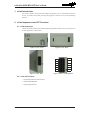
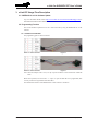
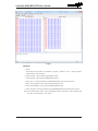
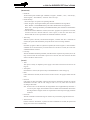
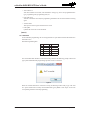
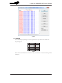
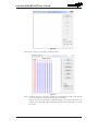
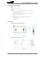
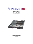
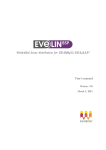
e-Link for 8-Bit MCU ICP User’s Guide
Revision: V1.00
Date: ������������
May 13, 2015
e-Link for 8-Bit MCU ICP User’s Guide
Table of Contents
1. e-Link Introduction.......................................................................................... 3
2. e-Link Appearance and ICP Functions.......................................................... 3
2.1 e-Link Appearance.................................................................................................................3
2.2 e-Link ICP Functions..............................................................................................................3
3. e-Link ICP Usage Flow Description............................................................... 4
3.1 HOPE3000 for e-Link Software Update.................................................................................4
3.2 Programming Function...........................................................................................................4
3.2.1 Holtek 8-bit Flash MCU....................................................................................................4
3.2.2 SPI Flash.........................................................................................................................7
3.2.3 EEPROM.........................................................................................................................8
4. e-Link Switch and Indicators......................................................................... 10
5. e-Link Size....................................................................................................... 10
Rev. 1.00
2
May 13, 2015
e-Link for 8-Bit MCU ICP User’s Guide
1. e-Link Introduction
The e-Link is Holtek’s third generation simulator/programmer for use with Holtek Flash MCU
devices. It includes both OCDS (On-Chip Debug Support) and ICP (In-Circuit Programming)
functions.
2. e-Link Appearance and ICP Functions
2.1 e-Link Appearance
e-Link is the common name for the Holtek simulator/programmer hardware series all of which have
the same appearance as shown below.
Figure 1. e-Link – Front
Figure 2. e-Link – Back
Figure 3. e-Link – Side
12
11
10
9
8
7
6
5
4
3
2
1
Figure 4. e-Link – Pin Assignment
2.2 e-Link ICP Functions
• Programming Holtek 8-bit Flash MCUs
• Programming EEPROMs
• Programming SPI Flash
Rev. 1.00
3
May 13, 2015
e-Link for 8-Bit MCU ICP User’s Guide
3. e-Link ICP Usage Flow Description
3.1 HOPE3000 for e-Link Software Update
Log on to the Holtek official website (http://www.holtek.com.cn/China/tech/tool/Mainpage1.htm) to
download and install the latest HOPE3000 for use with the e-Link.
3.2 Programming Function
The e-Link should be updated to be in the e-Link ICP mode by using the HOPE3000 for e-Link
software.
3.2.1 Holtek 8-bit Flash MCU
The programming pins are shown as follows:
Table 1. 5-wire Connection
Figure 5
Table 2. 4-wire Connection
Figure 6
Note: When the adaptor lead is used, a 0.1μF capacitor should be connected between VDD and
GND.
Before ICP operation, first click “File” → “Open” to open the MTP file to be programmed, then
correctly connect the target Holtek 8-bit Flash MCU.
The initialisation interface of the HOPE3000 for e-Link software is as follows.
Rev. 1.00
4
May 13, 2015
e-Link for 8-Bit MCU ICP User’s Guide
Figure 7
【Upload】
• Upload
The upload option includes six commands, “Program”, “EEData”, “ALL”, “Verify Program”,
“Verify EEData” and “Verify All”.
• Select “Program”: Only read the Program Memory data.
• Select “EEData”: Only read the EEPROM Memory data.
• Select “ALL”: The Program Memory and EEPROM Memory data will both be read.
• Select “Verify Program”: Only verify the Program Memory data.
• Select “Verify EEData”: Only verify the EEPROM Memory data.
• Select “Verify All”: The Program Memory and EEPROM Memory data will both be verified.
Note: The read data will be shown in the corresponding window. If the data is to be stored then click
the “Save” button under the “File” option.
Rev. 1.00
5
May 13, 2015
e-Link for 8-Bit MCU ICP User’s Guide
【Download】
• Download
The download option includes eight commands, “Program”, “EEData”, “ALL”, “Auto Verify”,
“Erase Program”, “Erase EEData”, “Erase All” and “Lock Chip”.
• Download Steps:
1. Click “File/Open” to open the corresponding .MTP file.
2. Select “Program”: The Program Memory data will be downloaded to the target MCU.
Select “EEData”: The EEPROM Memory data will be downloaded to the target MCU.
Select “ALL”: The Program Memory and EEPROM Memory data will both be downloaded to
the target MCU.
3. After the download command is executed, if the MCU programs are required to be executed,
click the “Power On” function under the “Tools” option, or select the “Auto Power On”
function under the “Tools” option before the download command is executed.
• Auto Verify
When this option is selected, if the download “Program”, “EEData” and “ALL” commands are
executed, the system will automatically verify data for the current executing command.
• Erase
If the MCU programs or data are required to be updated, the “Erase Program” or “Erase EEData”
command can be executed directly as needed. However if the MCU is locked, the “Erase All”
command should be executed.
• Lock Chip
After the download command is performed, if the MCU data is required to be protected, the “Lock
Chip” function under the “Download” option can be executed. This will ensure that the data
written to the MCU cannot be read.
【Tools】
• Tools
This option is mainly to implement power supply control and reset function selection for the
target IC.
• View Option
If this function is selected, the options setup in the HOPE3000 for e-Link will pop up.
• Reset
If this command is executed, the MCU will be forced to return to the program initial state and
rerun.
• Power On
If the power has been successfully connected, then after the command is executed, the program
downloaded to the MCU will run. The voltage is either 3.3V or 5V, which users can choose
according to their needs.
Note: If users want to use the ICP mode, the Target Board can be supplied directly with either a
3.3V or 5V power supply. The maximum current is 300mA which should meet the needs of
most target boards. If higher currents are required then an external power supply should be
connected.
• Power Off
After this command is executed the target IC will have no power and the programs will not run.
• Auto Power On
Function: After the “Download”, “Upload” and other commands are executed, the system will
supply power to the devices automatically.
Rev. 1.00
6
May 13, 2015
e-Link for 8-Bit MCU ICP User’s Guide
• View S.W.A.R.T
After this command is executed, some information will pop up, such as the programmed MCU
type, programming time, programming times, etc.
• Erase S.W.A.R.T
After this command is executed, the programming information will be cleared without executing
again.
• Activate Writer
This option is used to register and activate the e-Link.
• F/W Update
Update F/W version for e-Link ICP Mode.
【Extra】
3.2.2 SPI Flash
For the SPI Flash programming, the current supported device part number includes the MX25 series
and SST25 series.
SPI Flash Programming Pins:
12 ×
11 GND
10 ×
9
×
8
CEB
7
×
6
MOSI
5
×
4
SCK
3
×
2
MISO
1
VDD
Table 3
The external SPI Flash should be connected correctly; otherwise the following prompt window will
pop up and normal SPI Flash programming operation cannot be carried out.
Figure 8
When the external SPI Flash is connected correctly, the following window will pop up. The “Part
No.” option will show the currenlyt connected SPI Flash type by default. Click “Open” to select the
corresponding .dat file for normal programming.
Rev. 1.00
7
May 13, 2015
e-Link for 8-Bit MCU ICP User’s Guide
Figure 9
3.2.3 EEPROM
For the EEPROM programming, the current supported device part number is the HT24 series.
Programming Pins:
12 ×
11 GND
10 ×
9
×
8
×
7
×
6
SCL
5
×
4
×
3
×
2
SDA
1
VDD
Table 4
When the external EEPROM is connected correctly, if this function is used, the following window
will pop up.
Rev. 1.00
8
May 13, 2015
e-Link for 8-Bit MCU ICP User’s Guide
Figure 10
Click “Open” to open the corresponding .bin file as follows.
Figure 11
Note: 1. If address pins A2, A1 and A0 are checked, the corresponding pin is high, if not checked,
the corresponding pin is low and the default state is not checked.
2. Address pins A2, A1 and A0 will be adjusted according to the opened .bin file size. For
example, if the opened file is 8K bits (HT24LC08), then only A2 is selectable, A1 and A0
are invalid.
Rev. 1.00
9
May 13, 2015
e-Link for 8-Bit MCU ICP User’s Guide
4. e-Link Switch and Indicators
• Switch
The switch is used to reset the e-Link.
• Indicators
Status: Yellow indicates that programming is OK and the power is connected
Flashing: OK or power on initial state
Continuously on: Represents the execution of “Tools” → “Power On” function
Error: Red indicates the programming is in a fail state
Flashing: Fail
Active: Blue indicates whether the programming is in Ready or Busy state
Continuously off: Ready
Flashing: Busy
5. e-Link Size
• e-Link back and side dimensions (unit: mm)
Figure 12
• e-Link back slot dimensions (unit: mil)
Figure 13
Rev. 1.00
10
May 13, 2015
e-Link for 8-Bit MCU ICP User’s Guide
Copyright© 2015 by HOLTEK SEMICONDUCTOR INC.
The information appearing in this Data Sheet is believed to be accurate at the time
of publication. However, Holtek assumes no responsibility arising from the use of
the specifications described. The applications mentioned herein are used solely
for the purpose of illustration and Holtek makes no warranty or representation that
such applications will be suitable without further modification, nor recommends
the use of its products for application that may present a risk to human life due to
malfunction or otherwise. Holtek's products are not authorized for use as critical
components in life support devices or systems. Holtek reserves the right to alter
its products without prior notification. For the most up-to-date information, please
visit our web site at http://www.holtek.com.tw.
Rev. 1.00
11
May 13, 2015