1
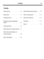
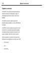
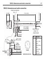
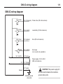
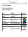
Installation and user’s guide
H-2000-5256-05-A
OMI-2C optical machine interface
English
1
English
Installation and user's guide
OMI-2C optical machine interface
This page is intentionally left blank
1-i
© 2005-2014 Renishaw plc. All rights reserved.
Disclaimer
This document may not be copied or reproduced in whole
imply freedom from the patent rights of Renishaw plc.
RENISHAW HAS MADE CONSIDERABLE EFFORTS
TO ENSURE THE CONTENT OF THIS DOCUMENT
IS CORRECT AT THE DATE OF PUBLICATION BUT
MAKES NO WARRANTIES OR REPRESENTATIONS
REGARDING THE CONTENT. RENISHAW EXCLUDES
LIABILITY, HOWSOEVER ARISING, FOR ANY
INACCURACIES IN THIS DOCUMENT.
Trade marks
Warranty
RENISHAW and the probe symbol used in the
Equipment requiring attention under warranty must be
returned to your equipment supplier.
or in part, or transferred to any other media or language,
by any means, without the prior written permission of
Renishaw.
The publication of material within this document does not
RENISHAW logo are registered trade marks of Renishaw
plc in the United Kingdom and other countries. apply
innovation and names and designations of other
Renishaw products and technologies are trade marks of
Renishaw plc or its subsidiaries.
All other brand names and product names used in this
document are trade names, trade marks, or registered
trade marks of their respective owners.
Renishaw part no: H-2000-5256-05-A
Issued: 07.14
Unless otherwise specifically agreed in writing
between you and Renishaw, if you purchased the
equipment from a Renishaw company the warranty
provisions contained in Renishaw’s CONDITIONS
OF SALE apply. You should consult these conditions
in order to find out the details of your warranty but in
summary the main exclusions from the warranty are if
the equipment has been:
•
neglected, mishandled or inappropriately used;
or
•
modified or altered in any way except with the
prior written agreement of Renishaw.
If you purchased the equipment from any other
supplier, you should contact them to find out what
repairs are covered by their warranty.
1-ii
CE, FCC statements and WEEE directive
c
EC declaration of conformity
Renishaw plc declares that the OMI-2C optical machine
interface complies with the applicable standards and
regulations.
Contact Renishaw plc at www.renishaw.com/omi-2c for
the full EC declaration of conformity.
WEEE directive
FCC
Information to user (FCC Section 15.19)
This device complies with Part 15 of the FCC rules.
Operation is subject to the following conditions:
1. This device may not cause harmful interference.
2. This device must accept any interference received,
including interference that may cause undesired
operation.
Information to user (FCC Section 15.21)
The user is cautioned that any changes or modifications
not expressly approved by Renishaw plc or authorised
representative could void the user’s authority to operate
the equipment.
Information to user (FCC Section 15.105)
The use of this symbol on Renishaw products and/or
accompanying documentation indicates that the product
should not be mixed with general household waste
upon disposal. It is the responsibility of the end user to
dispose of this product at a designated collection point
for waste electrical and electronic equipment (WEEE)
to enable reuse or recycling. Correct disposal of this
product will help to save valuable resources and prevent
potential negative effects on the environment. For more
information, please contact your local waste disposal
service or Renishaw distributor.
This equipment has been tested and found to comply
with the limits for a Class A digital device, pursuant to
part 15 of the FCC Rules. These limits are designed
to provide reasonable protection against harmful
interference when the equipment is operated in a
commercial environment. This equipment generates,
uses and can radiate radio frequency energy and,
if not installed and used in accordance with this
installation guide, may cause harmful interference to
radio communications. Operation of this equipment in a
residential area is likely to cause harmful interference,
in which case you will be required to correct the
interference at your own expense.
Patent and safety notices
Patent notice
Features of OMI-2C optical machine interface,
and other related products, are the subject of one
or more of the following patents and/or patent
applications:
EP 0974208
US 6839563
EP 1503524
JP 429401
Information for the user
There are no user serviceable parts inside the
OMI-2C. Return defective units to an authorised
Renishaw Customer Service Centre. Please
quote the serial number.
Remove power before performing any
maintenance operations.
CNC machine tools must only be operated
by competent persons in accordance with the
machine supplier’s operating instructions.
1-iii
Information for the machine’s
supplier
It is the responsibility of the machine’s supplier
to ensure that the user is made aware of any
hazards involved in operation, including those
mentioned in Renishaw product documentation,
and to ensure that adequate guards and safety
interlocks are provided.
1-iv
Preliminary information
Environment
IP rating
The front face of the OMI-2C is sealed to IPX8
(when the unit is correctly installed).
Temperature
Storage: The OMI-2C should be stored in an
area where the ambient temperature will remain
between –10 °C and 70 °C (14 °F to 158 °F).
Operation: The OMI-2C may be operated in
ambient temperatures of between 0 °C and 60 °C
(32 °F and 140 °F).
Specification
Weight of unit with retaining bracket:
70 g (2.5 oz)
Care of the equipment
The OMI-2C should be kept clean from dirt,
coolant and machining debris at all times,
otherwise the transmission range may be
reduced. Wipe the window clean as often as is
necessary to maintain unrestricted transmission.
When handling, treat the OMI-2C with care. It is a
precision component that can be easily damaged.
Do not apply labels to, or otherwise obstruct, the
window of the OMI-2C.
Contents
1-1
Contents
System overview . . . . . . . . . . . . . .
1-2
OMI-2C electrical outputs and inputs . . . 1-10
Typical system . . . . . . . . . . . . . . . . 1-3
OMI-2C visual diagnostics . . . . . . . . . 1-11
System performance . . . . . . . . . . . .
1-4
OMI-2C output waveforms . . . . . . . . . 1-12
Performance envelope of OMP60 and
OMI-2C . . . . . . . . . . . . . . . . . . .
1-5
Fault finding . . . . . . . . . . . . . . . . 1-13
Mounting the OMI-2C . . . . . . . . . . . . 1-6
OMI-2C dimensions and cable connection .
1-7
OMI-2C cable recommendation and
electrical connection . . . . . . . . . . . . . 1-8
OMI-2C wiring diagram . . . . . . . . . . .
1-9
Parts list . . . . . . . . . . . . . . . . . . 1-17
1-2
System overview
System overview
The OMI-2C provides an interface between the
machine controller and Renishaw’s range of
modulated transmission probes, such as the
OMP60.
The OMI-2C converts optical signals into
electrical signals suitable for use by the machine
controller.
The OMI-2C converts electrical signals from the
controller into modulated optical probe signals.
This facility allows the machine controller to be
used to optically switch the probe on and off.
When in operation, the OMI-2C will report the
following probe conditions via a multi-colour LED:
•
Probe status
•
Error
•
Low battery
Typical system – OMP60 probe with OMI-2C
CNC machining
centre spindle
1-3
Cable
CNC
machine
control
OMI-2C
(optical machine
interface)
OMP60 probe
Serial No. V68739
Stylus
Workpiece
1-4
System performance
System performance
Operating envelope
Reflective surfaces within the machine cabinet
may increase the signal transmission range.
Coolant residue accumulating on the windows
of the OMI-2C and OMP will have a detrimental
effect on transmission performance. Wipe the
windows clean as often as is necessary to
maintain unrestricted transmission.
For best system performance, ensure that the
OMI-2C is mounted in a position which is not
directly in front of a light source.
!
CAUTION: If two systems are operating in
close proximity, take care to ensure that signals
transmitted from the OMP on one machine are
not received by the OMI-2C on the other machine
and vice versa.
Performance envelope of OMP60 probe and OMI-2C
Performance envelope of OMP60
probe and OMI-2C
1-5
Switch on/off
Operating – standard power mode
Operating – low power mode
OMP60 probe and OMI-2C
360° transmission around
probe axis in metres (feet)
The probe and OMI-2C diodes must be in each
other’s field of view, and within the performance
envelope shown. The OMP60 is fully described in
the OMP60 installation guide H-4038-8505.
1 (3.3)
2 (6.5)
3 (9.8)
4 (13.1)
5 (16.4)
6 (19.9)
7 (23.0)
8 (26.2)
9 (29.5)
75°
OMI-2C
60°
45°
OMP60
15°
0°
1 (3.3)
2 (6.5)
3 (9.8)
4 (13.1)
5 (16.4)
6 (19.9)
7 (23.0)
8 (26.2)
9 (29.5)
15°
30°
45°
75°
60°
75°
75°
30°
60°
60°
45°
45°
30°
30°
15°
15°
Optical
centre line
0°
Typical plot at 20 °C (68 °F).
Dotted line represents operating range
with OMP60 low optical power.
Range m (feet)
1-6
Mounting the OMI-2C
Mounting the OMI-2C
!
WARNING: Ensure the machine tool is
in a safe condition and power is removed before
removing covers. Only qualified persons should
adjust switches.
!
CAUTION: Different versions of the
OMI‑2C operate with specific machine controllers.
Prior to installation, ensure that the OMI-2C is
compatible with the machine controller.
The OMI-2C should be mounted as near to the
machine spindle as possible (as shown in the
system diagram on page 1-3).
To achieve the best possible transmission range
and performance envelope, it is recommended
that the mounting screw is positioned on the
far side of the OMI-2C, relative to the expected
probe position.
When mounting the OMI-2C, it is important that
the sealing ring forms a tight seal around the rim
of the bore into which the body of the OMI-2C is
to be located.
!
CAUTION: Make sure that the sealing
ring is lubricated prior to being mounted in the
machine spindle.
OMI-2C dimensions and cable connection
1-7
OMI-2C dimensions and cable connection
Ø17.1 (0.67)
111.5 (4.39)
29 (1.14)
11 (0.43)
22 (0.87)
Socket head capscrew
M4 × 12
14 (0.55)
View A
Ø17.7 (0.697)
Ø17.6 (0.693)
8 (0.31)
6.75 (0.27)
Ra 1.6 (64)
Installation
detail
Ø20 (0.79)
Ø18.7 (0.74)
30°
15°
Bore
diameter
Ø18.02 (0.709)
Ø18.00 (0.708)
2.8 (0.11) MAX
6 (0.24) minimum depth
View A
dimensions mm (in)
Binder connector
(Series 712)
09-0427-80-08
Pin
Function
1
2
3
4
5
6
7
8
0V
15 V – 30 V
Start
Probe status
Error
Low battery
Screen
Not used
1-8
OMI-2C cable recommendation and electrical connection
Cable recommendation
OMI-2C electrical connection
Cables must be routed carefully to avoid potential
sources of electromagnetic interference.
OMI-2C power supply
Cable specification
Ø4.5 mm (0.18 in) to Ø5.0 mm (0.20 in), 12 core
screened cable each core 7/0.1 mm.
Standard cable variants
The OMI-2C standard polyurethane cables are
8 m (25 ft) and 15 m (49 ft) long.
NOTE: Maximum length of the specified cable
must not exceed 30 m (98 ft).
The OMI-2C requires a suitably fused (500 mA)
24 volt clean power supply, which is capable of
providing up to 200 mA of current. The supply
can be taken from the machine, or via an external
power supply. It is important that any input voltage
ripple will not cause the voltage to fall below 15
volts or rise above 30 volts.
Connection of the OMI-2C to the power supply
is achieved via the 8 pin connector located on
the rear of the OMI-2C. If a Renishaw cable is
supplied then the colours shown in the diagram
opposite can be used.
OMI-2C wiring diagram
1-9
OMI-2C wiring diagram
Driver
Pin 4 (turquoise) Probe status (20 mA maximum)
Driver
Pin 6 (violet)
Low battery (20 mA maximum)
Driver
Pin 5 (green)
Error (20 mA maximum)
Pin 3 (white)
Start input
0V
0V
0V
Buffer
(15 V to 30 V, 19 mA@30 V)
15 V to 30 V
Pin 2 (red)
0 V Pin 1 (black)
Screen
Power supply (15 V to 30 V)
(200 mA maximum)
Pin 7 (grey)
Machine ground
(star point)
!
CAUTION: The power supply 0 V
should be terminated at the machine
ground (star point).
1-10
OMI-2C electrical outputs and inputs
OMI-2C outputs
The OMI-2C has three electrical outputs which
are driven relative to the ground connection:
Probe status (pin 4)
Error (pin 5)
Low battery (pin 6)
The maximum rated sink or source current per
output is 20 mA. If this current is exceeded,
the OMI-2C isolates all outputs and the visual
diagnostics LED will flash red.
When an 8 m Renishaw cable assembly is used
and outputs are driven high, they may be up to
2 V below the supply voltage. Alternatively, when
the outputs are driven low, they may be up to 2 V
above 0 V.
When a 15 m Renishaw cable assembly is used
and outputs are driven high, they may be up to
2.5 V below the supply voltage. Alternatively,
when the outputs are driven low, they may be up
to 2.5 V above 0 V.
NOTE: Refer to parts list for Renishaw OMI-2C
cable assemblies.
The OMI-2C will respond to a received probe
trigger signal with a delay of 500 µs ±15 µs. The
time delay from the physical probe trigger to any
output change will depend on the configuration of
the probe.
OMI-2C input
The OMI-2C has a single electrical input that
allows the machine controller to switch the
probe on and off. The start input (pin 3) must
be connected to the machine’s start and stop
M-code.
When the input is active (15 V to 30 V,
19 mA@30 V), the probe is switched on.
OMI-2C visual diagnostics
1-11
OMI-2C visual diagnostics
When in operation, the OMI-2C displays its
present status via a multicoloured LED located
behind the front window. The LED display
configuration is as shown below.
LED
Probe status
Flashing green (for 3 seconds on
power up)
Controller type: Heidenhain i530/
Siemens 840D
Constant red
Probe on and triggered
Constant green
Probe on and seated
Constant blue
Probe error or probe off
Flashing blue and red
Low battery when probe is triggered
Flashing blue and green
Low battery when probe is seated
Yellow flash (0.5 second duration)
Start/stop signal
Flashing red
Overcurrent condition (reset OMI-2C by
removing power)
Graphic hint
1-12
OMI-2C output waveforms
OMI-2C output waveforms
PROBE
Triggered
Seated
OMI-2C
OUTPUTS
Probe
switch on
Power off
Probe
status
Seated
Probe
reseat
Error
e.g. Low
signal
Error
clear
Low
battery
Output high
Trigger
low
Output low
Error
Output high
Normally
high
Output low
Low
battery
Output high
Normally
high
Probe
trigger
Output low
The ouput signals from the OMI-2C must be compatible with the machine control input.
Probe
switch
off
Fault finding
1-13
Fault finding
If in doubt, consult your probe supplier.
Symptom
Cause
Action
No LED display
when power is on.
No power supply.
Ensure that the power source has not been
isolated from the main electrical supply.
Cable used to connect the
OMI-2C to the power supply
has been damaged, is of
incorrect specification or has
been incorrectly wired.
Visually inspect the cable for obvious signs
of damage.
Test the cable to ensure the electrical
continuity of each wire.
Verify that the cable has been correctly
wired for use with the OMI-2C.
Rear pin connector
on OMI‑2C is loose or
disengaged.
Ensure rear pin connector is properly
engaged and secure.
Pins on electrical connector
damaged or missing.
Visually inspect the connector to ensure
that no pins are damaged or missing.
OMI-2C unit is itself defective.
Contact your supplier for assistance.
1-14
Fault finding
Symptom
Cause
Action
OMI-2C LED
continuously flashes
red.
Output signal has required
too high a current.
Confirm that the outputs from the OMI-2C
are correctly wired into the inputs of the
machine controller.
Reset the OMI-2C by first removing and
then reapplying the power supply to the
unit.
Disconnect all output wires and ensure
that none have been connected to a power
signal supply.
Probe fails to switch Installation/CNC program
on when in ‘optical
fault.
start’ mode or switch Beam obstructed.
off when in ‘optical
stop’ mode.
Incompatible probe/probe
transmission setting.
Correct M-code wiring and/or CNC
program.
Clean the OMI-2C window and remove any
obstructions.
Change probe or probe setting to
‘modulated’.
Dead probe batteries.
Replace probe batteries.
Optical interference is
blocking the start signal.
Remove source of interference.
Fault finding
1-15
Symptom
Cause
Action
Probe stops in
mid-cycle.
Beam obstructed.
Remove obstruction.
Optical interference.
Remove source of interference.
Intermittent wiring fault.
Correct wiring.
Probe is in ‘timer off’ mode
and has not been triggered for
the timer period.
Increase ‘timer off’ time setting or change
probing routine.
Probe has not been triggered
for more than 90 minutes.
Re-start probe and ensure that the probe is
not idle for 90 minutes.
Interfering light source shining
directly into OMI-2C window.
Remove source of interference.
A signal is being received
from a probe on an adjacent
machine.
Change the adjacent probe to low power
mode.
Installation/CNC program
fault.
Check error output and CNC program.
or
An unexpected error
occurs during a
probing cycle.
or
An unexpected
trigger occurs
during the probing
cycle.
Probe switches on,
but OMI-2C error
remains active.
1-16
Fault finding
Symptom
Cause
Action
Probe indicates ‘low
battery’ condition,
but the machine
control does not.
Installation/CNC programming
fault.
Check ‘low battery’ output wiring and/or
CNC program.
Machine control
does not respond
to the probe being
triggered or seated.
Probe is not switched on.
Attempt to switch it on.
Installation/CNC program
fault.
Correct ‘probe status’ output wiring and
CNC program.
A signal is being received
from a probe on an adjacent
machine tool.
Change the adjacent probe to ‘low power
mode’.
Probe fails to switch
on.
Probe was already on
when the start signal was
transmitted.
Check that the probe was turned off at the
end of the last probing cycle.
Parts list
1-17
Parts list
Please quote the part number when ordering
equipment.
Type
Part number
Description
OMI-2C kit
A-5314-0001
OMI-2C kit that is compatible with Heidenhain i530 or Siemens
840D controllers. Kit includes: OMI-2C, mounting kit, toolkit and
user’s guide.
Cable (8 m)
A-5314-0015
OMI-2C cable assembly, including 8 metres of cable.
Cable (15 m)
A-5314-0016
OMI-2C cable assembly, including 15 metres of cable.
This page is intentionally left blank.
Renishaw plc
New Mills, Wotton-under-Edge,
Gloucestershire, GL12 8JR
United Kingdom
T +44 (0)1453 524524
F +44 (0)1453 524901
E [email protected]
www.renishaw.com
For worldwide contact details, please
visit our main web site at
www.renishaw.com/contact
*H-2000-5256-05*