1
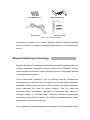
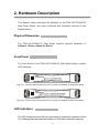
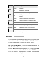
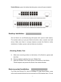
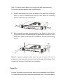
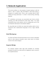
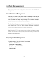
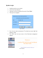
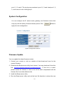
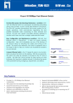
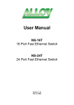
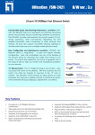
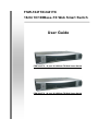
FSW-1641TX/2441TX 16/24 10/100Base-TX Web Smart Switch User Guide FSW-1641TX 16 port 10/100Base-TX Web Smart Switch FSW-2441TX 24 port 10/100Base-TX Web Smart Switch Contents 1. PRODUCT INTRODUCTION ...................................................................................1 Key Features.............................................................................................................1 Software Features.....................................................................................................2 Package Contents.....................................................................................................2 Ethernet Switching Technology.................................................................................3 2. HARDWARE DESCRIPTION ...................................................................................5 Physical Dimension...................................................................................................5 Front Panel ...............................................................................................................5 LED Indicators...........................................................................................................5 Rear Panel ................................................................................................................6 Desktop Installation...................................................................................................7 3. NETWORK APPLICATION ....................................................................................10 4. WEB MANAGEMENT ............................................................................................12 About Web-based Management .............................................................................12 Preparing for Web Management .............................................................................12 System Login ..........................................................................................................13 Port Status ..............................................................................................................14 Port Configuration ...................................................................................................16 VLAN Setting ..........................................................................................................17 Trunk Configuration.................................................................................................18 System Configuration..............................................................................................19 Firmware Update.....................................................................................................19 5. TROUBLESHOOTING ...........................................................................................21 6. TECHNICAL SPECIFICATION ..............................................................................23 i 1. Product Introduction LevelOne FSW-1641TX/2441TX, 16/24 10/100Base-TX Web Smart Switch, is a multi-port Switch that can be used to build high-performance switched workgroup networks. This switch is a store-and-forward device that offers low latency for high-speed networking and allows the switch to auto-learn and store source address in a 4K-entry MAC address table. The switch is targeted at workgroup, department or backbone computing environment. The 16/24 10/100Base-TX Web Smart Switch has 16 or 24 auto-sensing 10/100Base-TX RJ-45 ports. Key Features Conforms to IEEE 802.3, 802.3u and 802.3x 16 or 24 10/100BASE-TX Web-smart switch with default button IEEE802.3x Flow control: ¾ Pause-frame for full duplex mode ¾ Backpressure for half duplex mode Auto-MDIX on all ports N-way Auto-Negotiation Store-and-Forward switching architecture and no-blocking full wire speed Support switch back plane ¾ 16 port: 3.2 Gbps ¾ 24 port: 4.8 Gbps 4K-entry MAC address table Port Based priority supported Support PortBase VLAN Embedded 1.25 Mbits memory buffer Port Trunking supported 11” desktop design and internal power 1 Software Features Management Web interface management Link speed, Link mode, Port disable/Enable, Port configuration Port Flow control disable/Enable, Port Auto negotiation Port Base VLAN Port Based Priority Port Trunk Firmware Update Port Based VLAN, VLAN entry up to 16/24 groups System provide 2 queues for High and Low priority. Any port could be assigned to the trunking port. Per trunk group up to four members. Bootp firmware upgrade Package Contents Unpack the contents of the FSW-1641TX/2441TX and verify them against the checklist below. FSW-1641TX/2441TX Web Smart Switch Power Cord Four Rubber Feet User Guide Rack mount kit 16-port 10/100Base-TX Web Smart Switch 24-port 10/100Base-TX Web Smart Switch 2 Four Rubber Feet Rack-mounted Kit Power Cord This User Guide Figure 1-2. Package Contents Compare the contents of the Switch package with the standard checklist above. If any item is missing or damaged, please contact your local dealer for service. Ethernet Switching Technology Ethernet Switching Technology dramatically boosted the total bandwidth of a network, eliminated congestion problems inherent with CSMA/CD (Carrier Sense multiple access with Collision Detection) protocol, and greatly reduced unnecessary transmissions. This revolutionized networking. First, by allowing two-way, simultaneous transmissions over the same port (Full-duplex), which essentially doubled the bandwidth. Second, by reducing the collision domain to a single switch-port, which eliminated the need for carrier sensing. Third, by using the store-and-forward technology’s approach of inspecting each packet to intercept corrupt or redundant data, switching eliminated unnecessary transmission that slow the network. By employing address learning, which replaced the inefficient receiving port. Auto-negotiation regulates the speed and duplex of each port, based on the 3 capability of both devices. Flow-control allows transmission from a 100Mbps node to a 10Mbps node without loss of data. Auto-negotiation and flow-control may require disablement for some networking operations involves legacy equipment. Disabling the auto-negotiation is accomplished by fixing the speed or duplex of a port. Ethernet Switching Technology supplied higher performance at costs lower than other solutions. Wider bandwidth, no congestion, and the reduction in traffic is why switching is replacing expensive routers and inefficient hubs as the ultimate networking solution. Switching brought a whole new way of thinking to networking. 4 2. Hardware Description This Section mainly describes the hardware of the FSW-1641TX/2441TX Web Smart Switch, and gives a physical and functional overview of this Module Switch. Physical Dimension The FSW-1641TX/2441TX Web Smart Switch’s physical dimension is 266mm x 193mm x 44mm (Lx W x H). Front Panel The Front Panel of the FSW-1641TX/2441TX Web Smart Switch consists LED Indicators. Figure 2-1. The Front panel of the FSW-1641TX 16-port 10/100Base-TX Web Smart Switch Figure 2-2. The Front panel of the FSW-2441TX 24-port 10/100Base-TX Web Smart Switch LED Indicators The LED Indicators gives real-time information of systematic operation status. The following table provides descriptions of LED status and their meaning. 5 LED Status Description Green Power On Off Power is not connected Green In 100Mbps connection speed Power 100M In 10Mbps connection speed or no device Off LNK/ACT FDX/COL connect Green The port is connecting with the device. Blinks The port is receiving or transmitting data. Off No device attached. Green The port is operating in Full-duplex mode. Blinks Collision of Packets occurs in the port. Off In half-duplex mode Table 2-1. The Description of LED Indicators Rear Panel The 3-pronged power plug, default button, and 16 or 24 RJ-45 Ethernet ports are located at the rear Panel of the 16/24 10/100Base-TX Web Smart Switch. The Switch will work with AC in the range 100-240V AC, 50-60Hz. RJ-45 Ports (Auto MDI/MDIX): 16 or 24x 10/100 N-way auto-sensing for 10Base-T or 100Base-TX connections. [In general, MDI means connecting to another Hub or Switch while MDIX means connecting to a workstation or PC. Therefore, Auto MDI/MDIX means that you can connect to another Switch or workstation without changing non-crossover or crossover cabling. ] 6 Default Button: press the button that all system value will reset to default. Figure 2-2. The Rear Panel of FSW-1641TX Web Smart Switch Figure 2-2. The Rear Panel of FSW-2441TX Web Smart Switch Desktop Installation Set the Switch on a sufficiently large flat space with a power outlet nearby. The surface where you put your Switch should be clean, smooth, level and sturdy. Make sure there is enough clearance around the Switch to allow attachment of cables, power cord and allow air circulation. Attaching Rubber Feet A. Make sure mounting surface on the bottom of the Switch is grease and dust free. B. Remove adhesive backing from your Rubber Feet. C. Apply the Rubber Feet to each corner on the bottom of the Switch. These footpads can prevent the Switch from shock/vibration. Rack-mounted Installation The FSW-1641TX/2441TX ,16/24 10/100Base-TX Web Smart Switch, come with a rack-mounted kid and can be mounted in an EIA standard size, 19-inch 7 Rack. The Switch can be placed in a wiring closet with other equipment. Perform the following steps to rack mount the switch: A. Position one bracket to align with the holes on one side of the switch and secure it with the smaller bracket screws. Then attach the remaining bracket to the other side of the Switch. B. After attached mounting brackets, position the Switch in the rack by lining up the holes in the brackets with the appropriate holes on the rack. Secure the Switch to the rack with a screwdriver and the rack-mounting screws. Note: For proper ventilation, allow about at least 4 inches (10 cm) of clearance on the front and 3.4 inches (8 cm) on the back of the Switch. This is especially important for enclosed rack installation. Power On Connect the power cord to the power socket on the rear panel of the Switch. The other side of power cord connects to the power outlet. The internal power 8 supply of the Switch works with voltage range of AC in the 100-240VAC, frequency 50~60Hz. Check the power indicator on the front panel to see if power is properly supplied. 9 3. Network Application This section provides you a few samples of network topology in witch the Switch is used. In general, FSW-1641TX/2441TX Web Smart Switch is designed as a segment switch. That is, with its address table (4k MAC address) and high performance, it is ideal for interconnecting networking segments. PC, workstations, and servers can communicate each other by directly connecting with FSW-1641TX/2441TX Web Smart Switch. The switch automatically learns nodes address, which are subsequently used to filter and forward all traffic based on the destination address. By using Uplink port, the Switch can connect with another switch or hub to interconnect other small-switched workgroups to form a larger switched network. Small Workgroup The FSW-1641TX/2441TX Web Smart Switch can be used as a standalone switch to which personal computers, server, printer server, are directly connect to form small workgroup. Segment Bridge For enterprise networks where large data broadcasts are constantly processed, this switch is an ideal solution for department users to connect to the corporate backbone. 10 In the illustration below, two Ethernet switches with PCs, print server, and local server attached, are both connect to the Switch. All the devices in this network can communicate with each other through the Switch. Connecting servers to the Switch allow other users to access the data on server. 11 4. Web Management This section introduces the configuration and functions of the Web-Based management. About Web-based Management Inside the CPU board of the switch exists an embedded HTML web site residing in flash memory. It offers advanced management features and allow users to manage the switch from anywhere on the network through a standard browser such as Microsoft Internet Explorer. The Web-Based Management supports Internet Explorer 5.0. It is based on Java Applets with an aim to reduce network bandwidth consumption, enhance access speed and present an easy viewing screen. Note: By default, IE5.0 or later version does not allow Java Applets to open sockets. The user has to explicitly modify the browser setting to enable Java Applets to use network ports. Preparing for Web Management The default value of FSW-1641TX/2441TX is as below: IP Address: 192.168.16.1 Subnet Mask: 255.255.255.0 Default Gateway: 192.168.16.254 User Name: root Password: root 12 System Login 1. Install the switch on your network. 2. Launch the Internet Explorer. 3. Type http:// and the IP address of the switch. Press “Enter”. 4. The login screen appears. Login Interface 5. Key in the user name and password. The default user name “root” and password “ root ”. 6. Click ”OK”, then the home screen of the Web-based management appears. Home Interface 13 Port Status In Port status function, you can view all ports current status. Link Status: green means the port active. Gray means the port inactive. Speed: the port transmitting speed. Duplex: the port duplex mode. Flow Control: the port flow control status. 14 Port Status interface Select the port and click Counters button, you can see the port counter information as the following figure shown. Click 15 Refresh button to reset the counters. Click Cancel button will bring the screen back to previous page. Port Counter Information Interface Port Configuration You can configure speed, status, flow control, duplex mode, port base priority, port priority mapping and back pressure of each port. After configuration, click Apply button to apply the new configuration. Advertise 10M Half: when auto negotiation is enabling, you can set up the port speed is “On” or “Off”. Advertise 10M Full: when auto negotiation is enabling, you can set up the port speed is “On” or “Off”. Advertise 100M Half: when auto negotiation is enabling, you can set up the port speed is “On” or “Off”. Advertise 100M Full: when auto negotiation is enabling, you can set up the port speed is “On” or “Off”. Full Duplex Flow Control: when auto negotiation is enabling, you can set up the full duplex flow control status is “On” or “Off”. Auto Negotiation: set up the auto negotiation status. “Enable” means the port speed is auto negotiation and detect. The port speed has four modes and can be configured at the same time. “Disable” means the auto negotiation is in force status. You can configure the port speed in 16 “Speed” and “Duplex” selection. Speed: set the port speed is 100M or 10M. Duplex: set the port duplex mode. Port Priority Mapping: set per port priority level. Back Pressure Support: enable or disable back pressure function. Port configuration interface VLAN Setting The system supports 16/24 VLAN groups. Select the VLAN group # and port member. Use Apply <<Add button to add the VLAN group members and click button to complete the VLAN configuration. 17 VLAN Setting Interface Trunk Configuration The system supports only one trunk group. The trunk group supports up to 4 port members. If the port members more than 4, it will cause the system abnormal. Mark the port number and click Apply button to apply the setting. Trunk Configuration interface [Note] The trunk members must in the same VLAN group. Otherwise, the trunk function will not operate. For example: The VLAN group 1 members are 18 port 1, 2, 3, and 4. The trunk group members is port 1,2, 3 and 4 and port 1, 2, 3, and 4 are all in the VLAN group 1. System Configuration You can configure the IP, subnet mask, gateway, and firmware version that may vary with the factory firmware release period. Click Submit button to apply the new configuration. System Configuration Interface Firmware Update You can update the latest firmware version. 1. Contact your vendor or visit our website at http://www.level1.com for the newest firmware. 2. Download the Bootp server utility from Internet. You may download it from this link. http://perso.wanadoo.fr/philippe.jounin/tftpd32.html#Top If this link is invalid, please search the Internet or refer to the txt file which compressed with the firmware file for another effective link. 3. Install the Bootp server utility. 4. Run the Bootp server utility and set the boot file direction to where the new 19 firmware is. 5. Go to the Firmware Update interface and click Update button to star firmware loading. 6. After updated, please power off the switch and then power on the switch. Firmware Update Interface 20 5. Troubleshooting This section is intended to help you solve the most common problems on the FSW-1641TX/2441TX Web Smart Switch. Incorrect connections The switch port can auto detect straight or crossover cable when you link switch with other Ethernet device. For the RJ-45 connector should use correct UTP or STP cable, 10/100Mbps port use 2 pairs twisted cable and Gigabit 1000T port use 4 pairs twisted cable. If the RJ-45 connector is not correct pin on right position then the link will fail. For fiber connection, please notice that fiber cable mode and fiber module should be match. Faulty or loose cables Look for loose or obviously faulty connections. If they appear to be OK, make sure the connections are snug. IF that does not correct the problem, try a different cable. Non-standard cables Non-standard and miss-wired cables may cause numerous network collisions and other network problem, and can seriously impair network performance. A category 5-cable tester is a recommended tool for every 100Base-T network installation. Improper Network Topologies It is important to make sure that you have a valid network topology. Common topology faults include excessive cable length and too many repeaters (hubs) 21 between end nodes. In addition, you should make sure that your network topology contains no data path loops. Between any two ends nodes, there should be only one active cabling path at any time. Data path loops will cause broadcast storms that will severely impact your network performance. Diagnosing LED Indicators The Switch can be easily monitored through panel indicators to assist in identifying problems, which describes common problems you may encounter and where you can find possible solutions. IF the power indicator does turn on when the power cord is plugged in, you may have a problem with power outlet, or power cord. However, if the Switch powers off after running for a while check for loose power connections, power losses or surges at power outlet. IF you still cannot resolve the problem, contact your local dealer for assistance. Cabling RJ-45 ports: use unshielded twisted-pair (UTP) or shield twisted-pair ( STP ) cable for RJ-45 connections: 100Ω Category 3, 4 or 5 cable for 10Mbps connections or 100Ω Category 5 cable for 100Mbps connections. Also be sure that the length of any twisted-pair connection does not exceed 100 meters (328 feet). Gigabit port should use Cat-5 or cat-5e cable for 1000Mbps connections. The length does not exceed 100 meters. For more information please refer to Appendix section. 22 6. Technical Specification This section provides the specifications of FSW-1641TX/2441TX Web Smart Switch. IEEE 802.3 10BASE-T Ethernet, Standard IEEE 802.3u 100BASE-TX Fast Ethernet IEEE802.3x Flow Control and Back-pressure Protocol CSMA/CD Technology Store and forward switching architecture Per port: Link/Activity, Full duplex/Collision, LED Indicators 100M Per unit: Power Transfer Rate 14,880 pps Ethernet port, 148,800 pps Fast Ethernet port 10BASE-T: 2-pair UTP/STP Cat. 3, 4, 5 cable Network Cable EIA/TIA-568 100-ohm (100m) 100BASE-TX: 2-pair UTP/STP Cat. 5 cable EIA/TIA-568 100-ohm (100m) Back-plane 16ports: 3.2Gbps with full wire speed 24 ports: 4.8Gbps with full wire speed 23 MAC address 4K Mac with Auto Learning Memory 1.25Mbits Power Supply 100-240 VAC, 50~60Hz, 3.3V/4A Power 16 port: 14Watts(Maximum) Consumption 24 port: 18.5Watts(Maximum) Operation Temp. 0℃ to 45℃ (32℉ to 113℉) Operation Humidity 10% to 90% (Non-condensing) Storage Temp. -10℃ to 70℃ Dimensions EMI 266 mm (W) x 193 mm (D) x 44 mm (H);11 inch size FCC Class A, CE 24