1
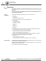
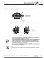
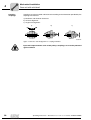
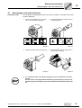
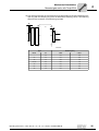
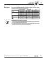
Mechanical Installation
Required tools / aids
4
Mechanical Installation
4.1
Required tools / aids
•
Set of spanners
•
Torque wrench for:
4
– Shrink discs
– AQH motor adapter
– Input shaft assembly with centering shoulder
•
Mounting device
•
Shims and distance rings if necessary
•
Fixing devices for input and output elements
•
Lubricant (e.g. NOCO® Fluid)
•
Bolt adhesive (for input shaft assembly with centering shoulder), e.g. Loctite® 243
•
Standard parts are not part of the delivery
Installation
tolerances
4.2
Shaft end
Flanges
Diameter tolerance in accordance with DIN 748
• ISO k6 for solid shafts with ∅ ≤ 50 mm
• ISO m6 for solid shafts with ∅ > 50 mm
• ISO H7 for hollow shafts
• Center bore in accordance with DIN 332, shape
DR
Centering shoulder tolerance in accordance with
DIN 42948
• ISO j6 with b1 ≤ 230 mm
• ISO h6 with b1> 230 mm
Prerequisites for assembly
Check that the following conditions have been met:
•
The data on the nameplate of the gearmotor matches the voltage supply system.
•
The drive has not been damaged during transportation or storage.
•
Ensure that the following requirements have been met:
– For standard gear units:
Ambient temperature according to the lubricant table in Sec. "Lubricants" (see
standard).
The drive must not be assembled in the following ambient conditions:
– Potentially explosive atmosphere
– Oil
– Acids
– Gas
– Vapors
– Radiation
– For special versions:
The drive configured in accordance with the ambient conditions.
– For helical-worm / SPIROPLAN® W gear units:
No large external mass moments of inertia which could exert a retrodriving load
on the gear unit.
[At η’ (retrodriving) = 2 – 1/η < 0.5 self-locking]
Operating Instructions – Gear Unit, R..7, F..7, K..7, S..7 Series, SPIROPLAN® W
15