1
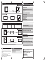
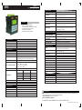
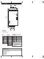
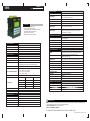
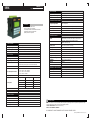
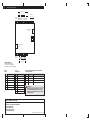
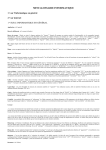
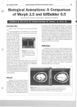
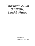
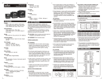
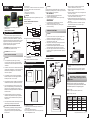
selec
MM303X Series (96x96)
Operating Instructions
To reduce noise:
A) Use of MOV / Snubber circuit across load / Contactors of
the unit and snubber circuits across the load are
recommended.
1. MOV Part no.: AP-MOV-03
2. Snubber Part no.: APRC-01.
CAUTION
Note: Diagram shown below is applicable only for PLC's
With Relay Outputs.
TYPICAL CONNECTIONS FOR LOADS :
For load current < 0.5A
N
L
This manual covers the following Selec PLC
product series.
MM3030, MM3032, MM3050
PLC
C
NO
PLC
C
Snubber
1. To prevent risk of electric shock, power supply to the
equipment must be kept OFF while wiring.
2. Terminals and electrically charged parts must not be
touched when the power is ON.
3. Wiring shall be done strictly according to the terminal
layout provided in the operating manual.
4. To eliminate electromagnetic interference use short
wire with adequate ratings and twists of equal size.
5. The power supply connection cable must have a cross
section of 1sq.mm or greater and insulation capacity of
atleast 1.5KV.
Electrical noise generated by switching of inductive
loads can create momentary disruption, erratic
display, latch up, data loss or permanent damage to
the instrument.
Fig. 4
MM3030
LOAD
NOTE: Use snubber as shown above to increase life of
internal relay.
B) Use separate shielded wires for inputs.
MOUNTING
A) PANEL MOUNTING
1
MECHANICAL INSTALLATION
2
3
4
5
6
7
8
9
+/-
ESC
0
92mm x 92mm
cut out
Fig. 1
1. Snap the controller onto the DIN rail as shown in Fig.
3 above.
2. When properly mounted, the controller is squarely
situated on the DIN-rail as shown in Fig. 4 above.
Outline dimensions (in mm)
99mm
99mm
90.5mm
COMMUNICATION
5mm
width
(max.)
MM3030
While making communication connections,
make sure that the power supply to the unit
is OFF.
62mm
4.5
mm
Panel Cutout (in mm)
1
2
3
4
5
6
7
8
9
+/-
Rubber
Seal
ESC
0
Fig. 2
Port 1 - Purpose & Scope
MM3030
For installing the controller
1. Prepare the panel cutout with proper dimensions as
shown above.
2. Remove the clamp from the PLC.
3. Fix the unit into the cutout. Insert the clamp from both
sides and tighten the screws.
MM303X series product have possibility of
2 communication ports please refer data sheets
of individual products for supporting ports.
Port 1 - RS232
Port 2 - IO Expansion (I0610 / I0630 series)
92mm
7. The output terminals shall be loaded strictly as per the
values/range specified by the manufacturer.
ELECTRICAL PRECAUTIONS DURING USE
B) DIN RAIL MOUNTING
Fig. 3
92mm
6. Thermal dissipation of equipment is met through
ventilation holes provided on housing of equipment.
Obstruction of these ventilation holes may lead to a
safety hazard.
C
C
4. The equipment shall not be installed in environmental
conditions other than those specified in this manual.
5. Since this equipment forms part of the main control
panel, its output terminals get connected to the host
equipment. Such equipment shall also comply to
EMI/EMC and safety requirements like BS EN 613261
and BS EN 61010.
Contactor
R
2. Conductors must not come in contact with the internal
circuitry of the equipment else it may lead to a safety
hazard that may endanger life or cause electrical
shock to the operator.
3. Circuit breaker or mains switch must be installed
between the power source and supply terminals to
facilitate power 'ON' or ‘OFF' function.
MAINTENANCE
1. To avoid blockage of ventilation holes, clean the
equipment regularly using a soft cloth.
2. Do not use Isopropyl alcohol or any other organic
solvents for cleaning.
CAUTION
NO
INSTALLATION INSTRUCTIONS
This equipment, being built-in-type, normally
becomes a part of the main control panel and the
terminals do not remain accessible to the user after
installation.
C
Snubber
For bigger loads use interposing relay/contactor
N
L
PLC
CAUTION: Risk of electric shock.
1.
EMC Guidelines:
1. Use proper input power cables with shortest
connections and twisted type.
2. Layout of connecting cables shall be away from any
internal EMI source.
WIRING INSTRUCTIONS
LOAD
R
CAUTION: Read complete instructions prior to
installation and operation of the unit.
CAUTION
The equipment in its installed state must not come in close
proximity to any heating sources, caustic vapors, oils,steam,
or other unwanted process byproducts.
1. Before you begin, note that the mounting panel
cannot be thicker than 5 mm (0.197”).
2. Make a panel cut-out measuring 92mm x 92mm
(3.622” x 3.622”).
3. Slide the controller into the cut-out, ensuring that the
rubber seal is in place.
4. Push the 2 mounting brackets into their slots on the
sides of the controller as shown in Fig. 1.
5. Tighten the bracket screws against the panel. Hold
the bracket securely against the unit while tightening
the screw.
6. When properly mounted, the controller is squarely
situated in the panel cut out as shown in Fig. 2.
PLC
SAFETY PRECAUTIONS
This manual is meant for person involved in wiring,
installation, operation and routine maintenance of the
equipment. All safety related codifications, symbols and
instructions that appear in this operating manual or on the
equipment must be strictly followed to ensure operator
and instrument safety. Any misuse may impair the
protection provided by the equipment.
CAUTION
1
2
3
4
5
6
7
8
9
+/-
0
ESC
Purpose
Protocol
Physical
medium
Connecting
Nodes
Downloading
MODBUS
RS232
PC to PLC
Uploading
MODBUS
RS232
PLC to PC
Online
Simulation
MODBUS
Slave
RS232
PLC to PC
As a slave in
RS485 network
MODBUS
Slave
RS485
PLC in RS485
network
Continue
Operating/1008/MM3030/OP291-V01 (Page 1 of 2)
COMMUNICATION
ORDERING INFORMATION
PC to PLC Download
Continued
ACCESSORIES (to be ordered separately)
Communication cable:
Part no. - ACH - 002.
PC
Port 1
RS232
downloading
USB to RS232
MM3030
Series
RS232
online
simulation
Windows-based software for ladder programming:
Part no. - ACD-003
PLC in RS485 Network
RS485
MODBUS
Master
RS232 to RS485
Converter
Relay module:
Part no. 1) AR - S8 - 24V - 1CO ( 1 Change over )
2) AR - S8 - 24V - 2CO ( 2 Change over )
Power Supply module:
Part No:
1) PS - CF – 24V - 1.1A
2) PS - CF – 24V - 2.5A
RS232
Port 1
RS232
RS232
IO Expansion Cable:
Part No: ACH-003
IO Expansion Adapter
Part No:- AC-IOEXP-01
IO610 Expansion Modules
Port 2 - Purpose & Scope
Purpose
Protocol
Medium
Supporting PLC Model
IO610 Expansion Module
MODBUS
RS485
MM3030-2
RS485 Network
MODBUS
RS485
MM3030-2
IO Expansion
Proprietary
Dedicated
MM3030-1 / MM3030-3 / MM3050
PLC to IO610
Port 2
IO
Expansion
IO Expansion
RS485
IO Expansion
Adapter
RS485
MM3030-2
IO610 Expansion
Modules / other
device supporting
modbus slave
IO610-4RO (4 Relay Outputs)
IO610-4TO (4 Transistor Outputs)
IO610-2AI-VI (2 Analog inputs (Voltage / Current))
IO610-2AI-TCR (2 Analog inputs (TC/RTD))
IO610-2AO (2 Analog Outputs)
IO630 Expansion Modules
Note: Applicable for MM3030-2 only
PLC to IO630
Port 2
IO
Expansion
IO610-8DI (8 Digital inputs)
IO630-8DI (8 Digital inputs)
IO630-4RO (4 Relay Outputs)
IO Expansion
IO Expansion
Adapter
IO630 Expansion
Modules
MM3030-1/-3
IO630-4TO (4 Transistor Outputs)
IO630-2AI-VI (2 Analog inputs (Voltage / Current))
Note: Applicable for MM3030-1, MM3030-3 & MM3050
Note: Upto 31 (Slave ID 1 to 31) expansion modules can be connected in network.
SERVICE DETAILS
This device contains no user serviceable parts and
requires special equipment and specialized engineers for
repair.
Please contact service center for repair on the following
numbers:
Toll free: 1800 227353 (BSNL/MTNL subscribers only)
Others: 91-22-40394200 / 40394202
NO WARRANTY ON UNIT DAMAGED DUE TO
WRONG POWER SUPPLY.
IO630-2AI-TCR (2 Analog inputs (TC/RTD))
IO630-2AO (2 Analog Outputs)
TO ORDER
Toll free: 1800 227 353
Phone: 91-22-28471 1882 / 4039 4200 / 4039 4202
Email: [email protected]
Fax: 91-22-2847 1733
Selec Controls Pvt. Ltd.
Specifications are subject to change, since development is a
continuous process
Telephone: +91-22-40394200 / 40394202
Fax: +91-22-28471733
Toll free: 1800 227 353
Website: www.selec.com
Email: [email protected]
Operating/1008/MM3030/OP291-V01 (Page 2 of 2)
selec
MM3030-1 (96x96)
Operating Instructions (SEPERATE)
OUTPUT SECTION
Digital Outputs
8 ( Transistorized )
Output Type
O0 & O1 - NPN @24V DC 50 mA,
O2 - O7 PNP @24V DC 100 mA.
Isolation
2kV
Yes
1ms (Also depends on Ladder scan time)
Short Circuit Protection
Min. Switching Time
FEATURES
Compact PLC with built-in HMI.
4 line x 16 character LCD display.
User friendly Windows based software for ladder
programming and HMI configuration
Special port for IO expansion.
Battery back up and RTC available
PWM Output
2 Channels @ O0 & O1,Pulse width: multiples of 1 ms,
Duty Cycle: 0.1% Least Count
Pulse Output
2 Channels @ O0 & O1
50 Khz -programming On & Off timers in 1 us resolution,
Programmable no of pulses.
FUNCTIONAL SPECIFICATIONS
Programming Method
SPECIFICATIONS
Display
LCD (backlight) 4 line x 16 character, Font size 5 x 7
Supply Voltage
20-30V DC (Minimum 1.1A SMPS recommended)
No. of Keys
15 (10 numeric keys)
No. of Configurable Keys
12
Windows based software for ladder programming and
HMI Configuration.
Memory
Data Memory: 16k, Code Memory: 351k, Upload Memory: 96 k
No. of Objects
Maximum 5000 (As per memory)
Minimum Scan Time
Typical Scan Time
200 µsec
1 ms (Also depends on ladder programming)
FUNCTIONAL BLOCKS
Timer
On Delay Timer, Off Delay Timer, Up Timer / Down Timer
(Special Timer). 1ms Timer & Pulse Timer
Counter
Up Counter, Down Counter & Up/Down Counter
(With & without over run)
Other Blocks
PID Control with auto tune, Totalizer, Rate totalizer,
PWM Output,Pulse output, Time Switch, Hysteresis & Scaling.
Memory Retention
10 years (4 Kb)
RTC
Yes
RS232 (Slave), I/O Expansion port
INPUT SECTION
Inputs
10 inputs
Input Type
I0 to I9 - PNP
Input Voltage
11-30 V DC
Response Time
Programmable from 1 to 255ms from Front End
(Default 10ms)(Also depends on ladder execution time)
Isolation
2kV
Communication Ports
Communication Protocols
Supported Expansion Series
Modbus RTU: RS232, Proprietary Protocol: I/O Expansion Port
No. of fast Input Channels
3 inputs
A) FC0 - I0 & I1 - Rate / Totalizer
B) FC1 - I2 & I3 - Rate / Totalizer
C) FC2 - I4 & I5 - Totalizer
Temperature range
Operating : 0 to 50O C, Storage : -20 to 60OC
Humidity
95% RH (Non Condensing)
Operating Modes
Unidirectional / Bidirectional / Quadrature Modes
Weight
348 gms
Order Code
MM3030-1
Input no
Operating Mode
Frequency
I0, I1
Uni / Bi
25KHz
I0, I1
Quad
10KHz
I2, I3
Uni / Bi / Quad
10KHz
I4, I5
Uni / Bi / Quad
10KHz
Max Speed.
Minimum Rate Measured
0.06Hz
Maximum Count
32 bits
IO630 Expansion modules
MECHANICAL SPECIFICATION
Mounting
Panel mounting & Din rail Mounting
Front Bezel / Side View
99 X 99 mm / 62 X 90.5 mm
Panel Cutout
92 X 92 mm
Din Rail
35 mm
ANALOG SECTION
Input
2 input (AI 0, AI 1)
Analog Sensor
Voltage (0-10V), Current (0-20mA) (Selectable via jumper)
Resolution
Accuracy
10 bit
Linearity
1 bit
0.1 %
SERVICE DETAILS
This device contains no user serviceable parts and requires special equipment and specialized engineers for repair.
Please contact service center for repair on the following numbers:
Toll free: 1800 227353 (BSNL/MTNL subscribers only)
Others: 91-22-40394200 / 40394202
NO WARRANTY ON UNIT DAMAGED DUE TO WRONG POWER SUPPLY.
Operating/1009/MM3030-1/OP295-V01 (Page 1 of 2)
TERMINAL CONNECTIONS
DIGITAL INPUTS
FC0
FC1
FC2
Analog Input
AI1
AI0
-
+
I0
I1
I2
I3
I4
I5
I6
I7
I8
+
I9
-
+
VI Jumpers
IO expansion port
(Port 2)
Internally
shorted
J4
J3
J2
J1
RS232 Comm. port
(Port 1)
+
-
O0 O1 O2 O3 O4 O5 O6 O7
24V DC
SUPPLY HS HS
DIGITAL OUTPUTS
PIN Configuration
MM3030-1 has two ports
Port 1- 6 Pin Jack (RS 232)
Port 2- 8 Pin Jack (IO Expansion)
Port 1
RS232
Port 2
IO Expansion
Jumper settings for Voltage & Current selection
for Analog channels
PIN
DESCRIPTION
PIN
DESCRIPTION
1
NC
1
NC
Sr. No. Jumper No
Description
1
J4
For Current Channel 1
2
GND
2
NC
2
J3
For Voltage Channel 1
3
TXD (RS 232)
3
GND
3
J2
For Current Channel 0
4
RXD (RS 232)
4
IO +ve
4
J1
For Voltage Channel 0
5
GND
5
IO -ve
6
NC
6
GND
7
NC
8
NC
CAUTION
Please ensure jumper settings as J1 & J3 are
selected before applying 10 VDC to Analog
channels. Ignoring this directive may damage
Analog channels
Selec Controls Pvt. Ltd.
Specifications are subject to change, since development is a continuous process.
Telephone: +91-22-40394200 / 40394202
Fax: +91-22-28471733
Toll free: 1800 227 353
Website: www.selec.com
Email: [email protected]
Operating/1009/MM3030-1/OP295-V01 (Page 2 of 2)
selec
MM3030-2 (96x96)
Operating Instructions (SEPERATE)
OUTPUT SECTION
Digital Outputs
8 ( Transistorized )
Output Type
O0 & O1 - NPN @24V DC 50 mA,
O2 - O7 PNP @24V DC 100 mA.
Isolation
2kV
Yes
1ms (Also depends on Ladder scan time)
Short Circuit Protection
Min. Switching Time
FEATURES
Compact PLC with built-in HMI.
4 line x 16 character LCD display.
User friendly Windows based software for ladder
programming and HMI configuration
Special port for IO expansion.
Battery back up and RTC available
PWM Output
2 Channels @ O0 & O1,Pulse width: multiples of 1 ms,
Duty Cycle: 0.1% Least Count
Pulse Output
2 Channels @ O0 & O1
50 Khz -programming On & Off timers in 1 us resolution,
Programmable no of pulses.
FUNCTIONAL SPECIFICATIONS
Programming Method
SPECIFICATIONS
Memory
Data Memory 16k, Code Memory : 351k, Upload Memory: 96 k
No of Objects
Maximum 5000 (As per memory)
200 µsec
Display
LCD (backlight) 4 line x 16 character, Font size 5 x 7
Supply Voltage
20-30V DC (Minimum 1.1A SMPS recommended)
Minimum Scan Time
Typical Scan Time
No. of Keys
15 (10 numeric keys)
FUNCTIONAL BLOCKS
No. of Configurable Keys
12
INPUT SECTION
Inputs
10 inputs
Input Type
I0 to I9 - PNP
Input Voltage
11-30 V DC
Response Time
Programmable from 1 to 255ms from Front End
(Default 10ms)(Also depends on ladder execution time)
2kV
No. of fast Input Channels
3 inputs
A) FC0 - I0 & I1 - Rate / Totalizer
B) FC1 - I2 & I3 - Rate / Totalizer
C) FC2 - I4 & I5 - Totalizer
Operating Modes
Unidirectional / Bidirectional / Quadrature Modes
Input no
Operating Mode
Frequency
I0, I1
Uni / Bi
25KHz
I0, I1
Quad
10KHz
I2, I3
Uni / Bi / Quad
10KHz
I4, I5
Uni / Bi / Quad
10KHz
Max Speed.
Minimum Rate Measured
0.06Hz
Maximum Count
32 bits
1 ms (Also depends on ladder programming)
Timer
On Delay Timer, Off Delay Timer, Up Timer / Down Timer
(Special Timer). 1ms Timer (max 4 blocks) & Pulse Timer
Counter
Up Counter, Down Counter & Up/Down Counter
(With & without over run)
Other Blocks
PID Control with auto tune, Totalizer, Rate totalizer,
PWM Output,Pulse output, Time Switch, Hysteresis & Scaling.
Memory Retention
10 years (4 Kb)
RTC
Yes
RS232 (Slave), I/O Expansion port (Master)
Communication Ports
Isolation
Windows based software for ladder programming and
HMI Configuration.
Communication Protocols
Supported Expansion Series
Modbus RTU: RS232, Modbus RTU : I/O Expansion Port
Temperature range
Operating : 0 to 50O C, Storage : -20 to 60OC
Humidity
95% RH (Non Condensing)
Weight
348 gms
Order Code
MM3030-2
IO610 Expansion modules
MECHANICAL SPECIFICATION
Mounting
Panel mounting & Din rail Mounting
Front Bezel / Side View
99 X 99 mm / 62 X 90.5 mm
Panel Cutout
92 X 92 mm
Din Rail
35 mm
ANALOG SECTION
Input
2 input (AI 0, AI 1)
Analog Sensor
Voltage (0-10V), Current (0-20mA)(Selectable via jumper)
Resolution
Accuracy
10 bit
Linearity
1 bit
0.1 %
SERVICE DETAILS
This device contains no user serviceable parts and requires special equipment and specialized engineers for repair.
Please contact service center for repair on the following numbers:
Toll free: 1800 227353 (BSNL/MTNL subscribers only)
Others: 91-22-40394200 / 40394202
NO WARRANTY ON UNIT DAMAGED DUE TO WRONG POWER SUPPLY.
Operating/1008/MM3030-2/OP304-V01 (Page 1 of 2)
TERMINAL CONNECTIONS
DIGITAL INPUTS
FC0
FC1
FC2
Analog Input
AI1
AI0
-
+
I0
I1
I2
I3
I4
I5
I6
I7
I8
I9
+
-
+
VI Jumpers
IO expansion port
(Port 2)
Internally
shorted
J4
J3
J2
J1
RS232 Comm. port
(Port 1)
+
-
O0 O1 O2 O3 O4 O5 O6 O7
24V DC
SUPPLY HS HS
DIGITAL OUTPUTS
PIN Configuration
MM3030-2 Has two ports
Port 1- 6 Pin Jack (RS 232)
Port 2- 8 Pin Jack (IO Expansion)
Port 1
RS232
Port 2
IO Expansion
Jumper settings for Voltage & Current selection
for Analog channels
PIN
DESCRIPTION
PIN
DESCRIPTION
1
NC
1
RS485 + ve
Sr. No. Jumper No
Description
1
J4
For Current Channel 1
2
GND
2
RS485 - ve
2
J3
For Voltage Channel 1
3
TXD (RS 232)
3
GND
3
J2
For Current Channel 0
4
RXD (RS 232)
4
NC
4
J1
For Voltage Channel 0
5
GND
5
NC
6
NC
6
GND
7
NC
8
NC
CAUTION
Please ensure jumper settings as J1 & J3 are
selected before applying 10 VDC to Analog
channels. Ignoring this directive may damage
Analog channels
Selec Controls Pvt. Ltd.
Specifications are subject to change, since development is a continuous process.
Telephone: +91-22-40394200 / 40394202
Fax: +91-22-28471733
Toll free: 1800 227 353
Website: www.selec.com
Email: [email protected]
Operating/1008/MM3030-2/OP304-V01 (Page 2 of 2)
selec
MM3030-3 (96x96)
Operating Instructions (SEPERATE)
OUTPUT SECTION
Digital Outputs
Relay Contact Rating
6 ( Relay )
3A (Resistive @ 240VAC)
Isolation
2kV
FUNCTIONAL SPECIFICATIONS
Programming Method
FEATURES
Compact PLC with built-in HMI.
4 line x 16 character LCD display.
User friendly Windows based software for ladder
programming and HMI configuration
Special port for IO expansion.
Windows based software for ladder programming and
HMI Configuration.
Memory
Data Memory: 16k, Code Memory: 351k, Upload Memory: 96 k
No of Objects
Maximum 5000 (As per memory)
Minimum Scan Time
Typical Scan Time
200 µsec
1 ms (Also depends on ladder programming)
FUNCTIONAL BLOCKS
Timer
On Delay Timer, Off Delay Timer, Up Timer / Down Timer
(Special Timer). 1ms timer (max 4 blocks) & Pulse Timer
Counter
Up Counter, Down Counter & Up/Down Counter
(With & without over run)
SPECIFICATIONS
Display
LCD (backlight) 4 line x 16 character, Font size 5 x 7
Other Blocks
PID Control with auto tune, Totalizer, Rate totalizer,
Time Switch, Hysteresis & Scaling.
Supply Voltage
90-270 V AC
Memory Retention
10 years (4 Kb)
No. of Keys
15 (10 numeric keys)
RTC
No. of Configurable Keys
12
Communication Ports
NO
RS232 (Slave), I/O Expansion port
Modbus RTU: RS232, Proprietary Protocol : I/O Expansion Port
8 inputs
Communication Protocols
Supported Expansion Series
Temperature range
Operating : 0 to 50O C, Storage : -20 to 60OC
Humidity
95% RH (Non Condensing)
Weight
343 gms
Order Code
MM3030-3
INPUT SECTION
Inputs
Input Type
I0 to I7 - PNP
Input Voltage
11-30 V DC
Response Time
Programmable from 1 to 255ms from Front End
(Default 10ms)(Also depends on ladder execution time)
Isolation
2kV
No of fast Input Channels
3 inputs
A) FC0 - I0 & I1 - Rate / Totalizer
B) FC1 - I2 & I3 - Rate / Totalizer
C) FC2 - I4 & I5 - Totalizer
Operating Modes
MECHANICAL SPECIFICATION
Unidirectional / Bidirectional / Quadrature Modes
Input no
Operating Mode
Frequency
I0, I1
Uni / Bi
25KHz
I0, I1
Quad
10KHz
I2, I3
Uni / Bi / Quad
10KHz
I4, I5
Uni / Bi / Quad
10KHz
Max Speed.
Minimum Rate Measured
0.06Hz
Maximum Count
32 bits
IO630 Expansion modules
Mounting
Panel mounting & Din rail Mounting
Front Bezel / Side View
99 X 99 mm / 62 X 90.5 mm
Panel Cutout
92 X 92 mm
Din Rail
35 mm
ANALOG SECTION
Input
2 input (AI 0, AI 1)
Analog Sensor
Voltage (0-10V), Current (0-20mA)(Selectable via jumper)
Resolution
Accuracy
10 bit
Linearity
1 bit
0.1 %
SERVICE DETAILS
This device contains no user serviceable parts and requires special equipment and specialized engineers for repair.
Please contact service center for repair on the following numbers:
Toll free: 1800 227353 (BSNL/MTNL subscribers only)
Others: 91-22-40394200 / 40394202
NO WARRANTY ON UNIT DAMAGED DUE TO WRONG POWER SUPPLY.
Operating/1008/MM3030-3/OP305-V01 (Page 1 of 2)
TERMINAL CONNECTIONS
DIGITAL INPUTS
FC0
FC1
FC2
Analog Input
AI1
AI0
12V DC
OUTPUT
+
- I0
I1
I2
I3
I4
I5
I6
+
I7
+
-
VI Jumpers
IO expansion port
(Port 2)
J4
J3
J2
J1
RS232 Comm. port
(Port 1)
L
N
NO0 NO1 NO2 NO3 NO4 NO5 COM
230V AC
SUPPLY
DIGITAL OUTPUTS
PIN Configuration
MM3030-3 has two ports
Port 1- 6 Pin Jack (RS 232)
Port 2- 8 Pin Jack (IO Expansion)
Port 1
RS232
Port 2
IO Expansion
Jumper settings for Voltage & Current selection
for Analog channels
PIN
DESCRIPTION
PIN
DESCRIPTION
1
NC
1
NC
Sr. No. Jumper No
Description
1
J4
For Current Channel 1
2
GND
2
NC
2
J3
For Voltage Channel 1
3
TXD (RS 232)
3
GND
3
J2
For Current Channel 0
4
RXD (RS 232)
4
IO + ve
4
J1
For Voltage Channel 0
5
GND
5
IO - ve
6
NC
6
GND
7
NC
8
NC
CAUTION
Please ensure jumper settings as J1 & J3 are
selected before applying 10 VDC to Analog
channels. Ignoring this directive may damage
Analog channels
Selec Controls Pvt. Ltd.
Specifications are subject to change, since development is a continuous process.
Telephone: +91-22-40394200 / 40394202
Fax: +91-22-28471733
Toll free: 1800 227 353
Website: www.selec.com
Email: [email protected]
Operating/1008/MM3030-3/OP305-V01 (Page 2 of 2)