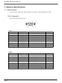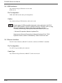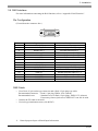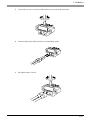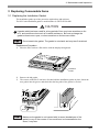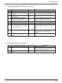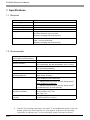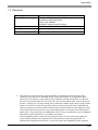
1
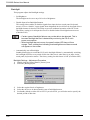
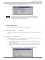
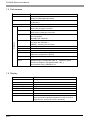
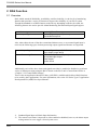
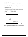
PS-600G Series
User Manual
Preface
Thank you for purchasing a Pro-face PS-600G Series Unit (PS600G-T41-E124V), hereafter referred to as
the PS-G unit.
Please read this manual carefully before installing the PS-G unit.
Important
1 The reproduction, copying or distribution of this equipment or its manual, either in whole or in part,
without written permission from Digital Electronics Corporation is prohibited.
2 The information provided in this manual is subject to change without notice.
3 Every effort has been made to ensure the information provided in this manual is accurate. Digital
Electronics Corporation would appreciate being informed of any errors or omissions.
4 Please be aware that Digital Electronics Corporation shall not be held liable by the user for any
damages, losses or third party claims arising from the use or application of this equipment.
© 2001, Digital Electronics Corporation. All rights reserved.
Windows is a registered trademark of Microsoft Corporation.
All other trademarks and registered trademarks are property of their respective owners.
1
Documentation Conventions
In this manual the following warning symbols are used to indicate important points concerning safe and
proper operation of the PS-G unit. Prior to operating the PS-G unit, be sure to read these points carefully.
Warning Symbols
This manual’s warning symbols indicate the following levels of danger.
WARNING
Failure to fully comply with points indicated by this
symbol may result in death or serious injury.
CAUTION
Failure to fully comply with points indicated by this
symbol may result in injury or equipment damage.
Indicates actions or procedures that should NOT be
performed.
Indicates actions or procedures that MUST be
performed to ensure proper operation.
The following mark is also used in this manual.
Refers to related information or an additional explanation.
2
Essential Safety Precautions
General Handling:
WARNINGS
Do not use the PS-G unit with aircraft control devices, aerospace equipment, central trunk data
transmission (communication) devices, nuclear power control devices, or medical life support
equipment, due to these devices’ inherent requirements of extremely high levels of safety and
reliability.
Do not use the PS-G unit as a warning device for critical alarms that can cause serious operator injury,
machine damage or production stoppage. Critical alarm indicators and their control/activator units must
be designed using stand-alone hardware and/or mechanical interlocks.
Do not use the PS-G unit in an environment where flammable gases are present. This may result in an
explosion.
Do not disassemble or modify the PS-G unit in any way (except for replacing the backlight). Doing so
may result in a fire or an electric shock.
When using the PS-G unit with transportation vehicles (trains, cars and ships), disaster and crime
prevention devices, various types of safety equipment, non-life support related medical devices, etc.
redundant and/or failsafe system designs should be used to ensure the proper degree of reliability and
safety.
Please be sure to design your system so that equipment will not malfunction due to a communication
fault between the PS-G and its host controller. This is to prevent any possibility of injury or damage.
Safety and emergency switches must be installed as separate hardware devices.
Do not create PS-G touch panel switches that could possibly endanger the safety of equipment and
personnel. This is because damage to the PS-G, its I/O unit(s), cable(s), and other related equipment
can cause an output signal to remain continuously ON or OFF and possibly cause a major accident. To
prevent this type of accident, design monitoring circuits using devices such as limit switches, etc. to
detect incorrect device movement. Also, to prevent accidents related to incorrect signal output, or
incorrect operation, design your system so that all switches used to control vital machine operations are
operated via a control system that is separate from the PS-G.
3
CAUTIONS
Do not strike the panel of the PS-G unit with a hard, heavy or pointed object, or press the panel with
excessive force. Doing so may result in panel damage or injury.
Do not allow liquids (including water), or metal objects to enter the PS-G unit. This may result in a
malfunction or an electric shock.
Do not block the PS-G unit’s ventilation opening does not become blocked and avoid using it in areas
where heat accumulates. Additionally, do not store or use it under high-temperature conditions.
Do not use or store the PS-G unit in locations subject to direct sunlight, or where excessive dust or dirt
is present.
Since the PS-G unit is a precision instrument, do not store or use it where large shocks or excessive
vibration can occur.
Do not store or use the PS-G unit in environments subject to chemical evaporation (such as that of
organic solvents), or where there are chemicals and acids present in the air.
Do not use paint thinner or organic solvents to clean the PS-G unit.
Important PS-G unit screen data should be backed up regularly.
The installation environment for the PS-G unit must satisfy the following requirements. Failure to do so
may cause the unit to malfunction.
Ambient temperature: 0°C to 50°C
Relative Humidity: 10%RH to 90%RH (Non-condensing)
The LCD panel contains a powerful irritant. If for any reason the panel is damaged and this liquid
contacts any part of your body, wash that area with running water for 15 minutes. Similarly, if any of
this liquid enters your eye, flush your eye with running water for 15 minutes and consult a physician.
4
During Installation:
WARNINGS
Do not use voltage levels other than those specified for the PS-G unit. Use of voltages outside this
range may result in a fire or an electric shock.
PS600G-T41-E124V: DC 24 V±20%
To reduce wire-to-wire or wire-to-earth noise as much as possible, use a low-noise power supply. In
addition, use a twisted-pair power cord.
Separate the PS-G unit’s power line from the power lines to other input/output or motor-driven devices.
Install a surge protector to protect against power surges.
Use a grounding resistance of 100Ω or less, or use your country’s applicable standard.
Confirm that the main power supply is turned OFF prior to connecting the power cord terminals.
Failure to do so may result in an electric shock.
Since the PS-G is not equipped with a power switch, be sure to connect a breaker-type power switch to
the power cord.
Install the PS-G unit in a vertical position - the unit is not designed to be operated in the horizontal
position.
If the PS-G unit is to be installed in a slanted panel, the panel should not incline more than 30° from the
vertical. If the panel inclines more than 30°, be sure to use forced-air cooling to ensure that the ambient
operation temperature does not exceed 50°C.
During Maintenance:
WARNINGS
Turn OFF the PS-G unit’s power supply prior to performing maintenance. Failure to do so may result in
burns or an electric shock.
Wear gloves when replacing the backlight. Failure to do so may result in burns.
5
PS-600G Series Model Numbers
The PS-600G Series is comprised of the following models.
Series
Model
PS600G-T11-J1
PS-600G
Description
International Ratings
Preinstalled with Windows ® CE
Not supported
3.0 (Japanese).
Input voltage AC100V.
Preinstalled with Windows ® CE
CE Marked, UL/c-UL
PS600G-T41-J124V 3.0 (Japanese)
(CSA) compliant.
Input voltage DC24V.
Preinstalled with Windows ® CE
CE Marked, UL/c-UL
PS600G-T41-E124V 3.0 (English)
(CSA) compliant.
Input voltage DC24V.
This manual’s explanation is the PS600G-T41-E124V unit.
PS-G Unit Application Software
The PS-G unit is pre-installed with the Windows® CE Operating System, which allows the PS-G unit to run
customer-developed applications.
For information concerning application software development environments and software integration
methods, please refer to the “PS Series Type G Application Development Kit (ADK) Developer Manual”.
6
UL/c-UL (CSA) Approval
The PS600G-T41-E124V and PS600G-T41-J124V is a UL/c-UL listed product. (UL file No. E182139)
The PS600G-T41-E124V and PS600G-T41-J124V conforms as a product to the following standards:
• UL 508 – Industrial Control Equipment
• UL 1604 – Electrical Equipment for use in Class I and II, Division 2, or Class III Hazardous (locations).
• CAN/CSA-C22.2, No. 1010-1
MEASUREMENT AND CONTROL EQUIPMENT
(Safety requirements for electrical equipment for measurement and laboratory use)
PS600G-T41-E124V/PS600G-T41-J124V (UL Registration Model: 2880045-22)
Installation Precautions
• The PS-G unit must be used as a built-in component of an end-use product.
• The PS-G unit should be installed so that it faces out from a panel.
• If the PS-G unit will be reliant on natural cooling, be sure to install it in a vertical panel. Also, be sure that
the PS-G unit is installed 100 mm away from any adjacent structures or other equipment. If these
requirements are not met, the heat generated by the PS-G unit’s internal components may cause the unit
to fail to meet UL and C-UL (CSA) standard requirements.
UL 1604 — Compliance and Handling Cautions
1. Power and input/output wiring must be in accordance with Class I, Division 2 wiring methods – Article
501 – 4(b) of the National Electrical Code, NFPA 70 within the United States, and in accordance with
Section 18-152 of the Canadian Electrical Code for units installed within Canada.
2. Suitable for use in Class I, Division 2, Groups A, B, C, and D, Hazardous Locations.
3. WARNING: Explosion hazard- substitution of components may impair compliance to Class I, Division
2.
4. WARNING: Explosion hazard – when in hazardous locations, turn the power OFF before replacing or
wiring modules.
5. WARNING: Explosion hazard – confirm that the power supply has been turned OFF before
disconnecting equipment, or confirm that the location is not subject to the risk of explosion.
CE Marking
The PS600G-T41-E124V and PS600G-T41-J124V is a CE marked product that conforms to EMC directives
EN55011 Class A, and EN50082-2.
7
Package Contents
The PS-G unit comes with the following items. After opening the packing box, please confirm that the
following items are included.
PS-G Unit (1)
Model Number: PS600G-T41-E124V
Installation Fasteners (4)
Installation Gasket (1)
(Pre-installed)
Operation Instructions (1)
CD-ROM (1)
8
CD-ROM Contents
The following items are included in the CD-ROM.
Product Name
Description
PS-600G Series
User Manual
PS-600G Series User Manual PDF file
Acrobat ® Reader 5.0
Required for viewing PDF files
(Self-extracting files)
9
Liquid Crystal Display (LCD) Characteristics
• Depending on the contents being displayed and the contrast settings of the PS-G unit, a wavelike pattern
of varying brightness (contouring) may appear. This is not a defect.
• There are minute grid-points (dark and light) on the Display Panel’s surface. This is part of the PS-G
unit’s design and not a defect.
• The colors on the display panel may appear to change when viewed from the side. This is a common
attribute of LCDs and is not a defect.
• An afterimage may appear on the display panel after a single screen that has been displayed for many
hours is changed to a different screen. The display panel will return to normal if switched off for a short
period of time. This is a common attribute of LCDs and is not a defect.
To prevent afterimages:
• Use the PS-G unit’s “Automatically turn off backlight” feature if you need to display the same screen for
long periods.
Refer to “Chapter 3 2.2 Control Panel Settings”.
• Periodically change the screen display.
For more information concerning other PS-G specifications, please contact your local Pro-face sales
representative.
Backlight Burnout Precautions
After the PS-G unit’s backlight burns out the screen will darken and the display will dissappear. If the
operator fails to notice that the backlight is burned out and touches the panel, a potentially dangerous
machine operation error can occur.
WARNINGS
Do not use PS-G touch switches for the control of any equipment safety mechanisms, such as
Emergency Stop switches, etc. that protect humans and equipment from injury and damage.
If your PS-G unit’s backlight suddenly turns OFF, use the following steps to determine if the backlight has
actually burned out.
• If your PS-G is not set to “Standby Mode” and the screen has gone blank, your backlight has burned out.
• Or, if your PS-G is set to Standby Mode, but touching the screen does not cause the display to reappear,
your backlight has burned out.
Also, to prevent accidental machine operation, Pro-face suggests you use the built-in “Disable Input After
Backlight Burnout” feature, that will automatically detect a burnout and disable the designated input
devices.
Refer to “Chapter 3 2.2 Control Panel Settings”.
10
Table of Contents
Preface ...................................................................................................................... 1
Documentation Conventions ..................................................................................... 2
Essential Safety Precautions .................................................................................... 3
PS-600G Series Model Numbers ............................................................................. 6
PS-G Unit Application Software ................................................................................ 6
UL/c-UL (CSA) Approval ........................................................................................... 7
CE Marking ............................................................................................................... 7
Package Contents ..................................................................................................... 8
CD-ROM Contents .................................................................................................... 9
Liquid Crystal Display (LCD) Characteristics .......................................................... 10
Backlight Burnout Precautions ................................................................................ 10
Chapter1 Introduction
1 System Design ................................................................................................... 1-2
2 Part Names and Functions ................................................................................ 1-4
3 Dimensions ........................................................................................................ 1-8
Chapter2 Installation
1 Installation Procedures ...................................................................................... 2-2
2 Connecting the Power Cord ............................................................................... 2-8
3 Interface Specifications .................................................................................... 2-10
3.1
3.2
3.3
3.4
3.5
3.6
3.7
3.8
Serial Interface ..................................................................................................... 2-10
Printer Interface .................................................................................................... 2-12
Keyboard and Mouse Connections ....................................................................... 2-13
USB Interfaces ..................................................................................................... 2-14
Ethernet Interface ................................................................................................. 2-14
RAS Interface ....................................................................................................... 2-15
Sound Output ....................................................................................................... 2-16
CF Card Insertion and Removal ........................................................................... 2-18
Chapter3 Start Up and Shut Down
1 Start Up ............................................................................................................. 3-2
2 Unit Settings ...................................................................................................... 3-3
2.1 Dip Switch Settings ................................................................................................. 3-3
2.2 Control Panel Settings ............................................................................................ 3-4
3 Internal Application .......................................................................................... 3-11
11
3.1
3.2
3.3
3.4
Version Information Psgver.exe .......................................................................... 3-11
Auto Start AutoRun.exe .................................................................................... 3-11
Terminal Services Connection Wizard TsConWiz.exe ........................................ 3-12
Applications for Pro-Designer Runtime Installation PDLoad.exe/PortChanger.exe 3-14
4 Shut Down ....................................................................................................... 3-14
Chapter4 Maintenance and Inspection
1 Regular Cleaning ............................................................................................... 4-2
2 Periodic Check Points ........................................................................................ 4-2
3 Replacing Consumable Items ............................................................................ 4-3
3.1 Replacing the Installation Gasket ........................................................................... 4-3
3.2 Replacing the Backlight .......................................................................................... 4-4
Chapter5 Troubleshooting
1 Troubleshooting Checklists ................................................................................ 5-2
1.1 No display (Windows CE does not start) ................................................................ 5-3
1.2 Touch panel does not respond ................................................................................ 5-3
1.3 Connected devices cannot be used. ....................................................................... 5-4
Appendices
1 Specifications ..................................................................................................... A-2
1.1
1.2
1.3
1.4
1.5
1.6
Electrical ................................................................................................................. A-2
Environmental .........................................................................................................A-2
Structural ................................................................................................................A-3
Performance ...........................................................................................................A-4
Display .................................................................................................................... A-4
Touch Panel ............................................................................................................ A-5
2 RAS Function ..................................................................................................... A-6
2.1 Overview ................................................................................................................ A-6
2.2 RAS Function - Details ........................................................................................... A-7
2.3 RAS Function Diagram .........................................................................................A-11
3 Accessories ..................................................................................................... A-12
Index
12
1
Introduction
1 System Design
2 Part Names and Functions
3 Dimensions
PS-600G Series User Manual
1 System Design
PS600G-T41-E124V
IrDA interface
Connector panel
Rear of PS-G unit
Laptop or similar device
Printer interface
Printer
Printer cable
(commercial type)
Ethernet interface
10BASE-T cable
(commercial type)
Hub
Central network line
Sound output
terminal block
Pin-jack cable
(GP077-SDAD10)
Speaker
USB interface
USB keyboard
USB mouse
Bar-code reader
RAS interface
User-prepared cable *1 Computer
PL Series
Unit
Host Controller
Expansion unit
interface 1
DIO unit
PSG-XY08
Expansion unit
interface 2
PCMCIA unit
PSG-PCM00
*1 Select a cable compatible with your system design. Refer to “Chapter 2 3.6 RAS Interface”.
1-2
1 Introduction
Side of PS-G unit
PS600G-T41-E124V
Keyboard/mouse
interface
Bar-code reader
PS/2 keyboard
PS/2 mouse
Connector panel
CF
CF Card
GP077-CF20 16MB
GP077-CF30 32MB
CF Card Adaptor
GP077-CFAD10
COM1/COM2
Data Transfer Cable
Computer
Supplied with PS series Type G
Application Development Kit (ADK)
PSG-CB01
Pro-Designer
PS-DWE01-V
**
(
indicates data that
changes depending on the version.)
**
PS Series Type G Application
Development Kit (ADK) PSG-DK01
Microsoft R eMbedded Visual Tools
For more information, refer to "PS
Series Type G Application
Development Kit (ADK) Developer
Manual".
RS-232C cable
(Commercial type)
Host controller (PLC)
1-3
PS-600G Series User Manual
2 Part Names and Functions
A, B
C, D
Front
A : Display Panel
Displays PS-G unit screen data.
B : Touch Panel
Provides “mouse-less” screen control.
C : Status LED
Indicates the PS-G unit’s status.
Green : Power ON/ Normal operation
At Start Up, the LED lamp changes from Red to Green
Orange : Indicates the RAS function and Backlight burnout
Red
: System Error
D : IrDA Interface
Provides infrared data transmission.
1-4
1 Introduction
F
G
E
Rear
E : Power Input Terminal Block
Connects the terminal block to the DC 24 V power source.
F : Expansion Unit Interface 1 (EXT1)
For DIO units.
G : Expansion Unit Interface 2 (EXT2)
This is a PCMCIA Bus interface.
For PCMCIA units.
1-5
PS-600G Series User Manual
Q
P O
N
M
H
L
K
I
J
Bottom
H
: CF Card Cover
Protects the CF Card slot.
I
: CF Card Slot
Accepts a standard CF Card.
J
: Printer Interface (PIO)
Connect your printer cable here. (Parallel)
K, L : Serial Interfaces (COM1, COM2)
Connect RS-232C cables here.
M
: RAS Interface (RAS)
Connect a RAS cable here.
N
: Ethernet Interface (10BASE-T)
Connect a 10BASE-T Ethernet cable here.
O
: Sound Output Terminal Block.
Connect a speaker or line output here.
P, Q : USB Interfaces 1 & 2 (USB1, USB2)
Connect USB (USB ver.1.0) compliant devices (keyboard, mouse, etc.) here.
1-6
1 Introduction
R
Side (Left)
R : Keyboard/Mouse Interface (PS/2)
Connect a PS/2 compatible keyboard or mouse here.
1-7
PS-600G Series User Manual
3 Dimensions
PS-600G
301 [11.85]
58 [2.28]
8
[0.31]
243 [9.57]
317 [12.48]
227 [8.94]
(Unit: mm [in.])
Installation Fasteners
(Unit: mm[in.])
31 [1.22]
1-8
19.5 [0.77]
16 [0.63]
11
[0.43]
φ10 [0.39]
M5
2
Installation
1 Installation Procedures
2 Connecting the Power Cord
3 Interface Specifications
3.1 Serial Interface
3.2 Printer Interface
3.3 Keyboard and Mouse Connections
3.4 USB Interface
3.5 Ethernet Interface
3.6 RAS Interface
3.7 Sound Output
3.8 CF Card Insertion and Removal
PS-600G Series User Manual
1 Installation Procedures
Check the installation conditions
Prepare the panel
Check the installation gasket
Install
Secure the installation fasteners
Installation Requirements
•
For easier maintenance, operation, and better ventilation, the space between the PS-G unit and
adjacent structures or equipment should be at least 100mm.
(Unit: mm [in.])
100
[3.94]
100 [3.94]
100
[3.94]
100
[3.94]
100
[3.94]
2-2
100
[3.94]
100 [3.94]
2 Installation
•
The ambient temperature of the PS-G unit should be between 0° C and 50° C. (Ambient
temperature refers to the temperatures measured in the panel interior and on the panel face.)
The ambient humidity should be 10% RH to 90% RH.
Panel
Face
•
Panel
Interior
Standard installation for the PS-G unit is in a vertical panel. If the PS-G unit is to be installed
in a slanted panel, the panel should not incline more than 30° from the vertical.
less than 30
from vertical
•
•
If the PS-G panel is to be installed in a slanted panel that inclines more than 30°, use forcedair cooling to ensure the ambient operation temperature does not exceed 50° C.
Horizontal installation (that is, rotating the panel so that one of its sides is the base) is not
supported.
2-3
PS-600G Series User Manual
Panel Preparation
The thickness of the panel should be from 1.6 mm to 10 mm [0.06 in. to 0.39 in.].
1.6 - 10 [0.06 - 0.39]
(Unit: mm [in.])
To ensure a sufficient level of water-resistance, make sure the panel is not
warped, damaged, or uneven. Attaching reinforcement strips also increases
the effectiveness of the PS-G unit’s installation gasket.
Panel Cut Dimensions
301.5
+1
0
[11.87
+0.04
0 ]
less than 4-R3
(Unit: mm [in.])
227.5 +10 [8.96 +0.04
]
0
Installation Gasket
The PS-G unit should always be installed using the pre-fitted installation gasket, even at locations
where water resistance is not required.
The installation gasket must be installed properly to ensure a sufficient level of water-resistance.
Before installing the PS-G unit please refer to “Chapter 4 3.1 Replacing the Installation Gasket”,
to confirm that the gasket is fitted properly.
2-4
2 Installation
Installation
Install the PS-G unit as follows:
1. Insert the PS-G unit into the cutout section of the panel with the touch screen facing outward.
2.
Insert the installation fastener hooks into the four (4) insertion slots (2 on the top and 2 on
the bottom).
Insertion slots
Insertion slots
Bottom
Top
Installation panel
Hook
2-5
PS-600G Series User Manual
2-6
3.
Slide the fastener toward the rear of the PS-G unit.
4.
Slowly tighten each fastener attachment screw in sequence (top, bottom, left side, right side),
until all fasteners are evenly and securely tightened. The proper torque for tightening an
attachment screw is 0.5N·m
2 Installation
CAUTIONS
Fastener attachment screws must be perpendicular to the panel. If they are not,
the PS-G unit may fall out of the panel.
Make sure the screws are tightened within the specified range of torque. Overtightening the fastener attachment screws may damage the PS-G unit.
• Depending on the strength of the panel, increasing the number of
installation fasteners can increase the PS-G unit’s water-resistance.
2-7
PS-600G Series User Manual
2 Connecting the Power Cord
WARNING
Confirm that the main power supply is turned OFF prior to connecting the power
cord terminals. Failure to do so may result in an electric shock.
CAUTIONS
The power supply for the PS600G-T41-E124V should be DC24V. Supplying any
other level of power can damage the PS unit or the power supply.
Since the PS-G is not equipped with the power switch, be sure to connect a
breaker-type power switch to the PS-G’s power cord.
Power Cord Cautions
•
•
•
•
•
•
To reduce wire-to-wire or wire-to-earth noise as much as possible, use a low-noise power
supply.
The PS-G unit power cords, the cables for input and output devices, and the power cords for
motor-driven equipment must be located separately.
To increase the noise resistance of the power cord’s wires, twist the strands before attaching
the Ring Terminals.
The main circuit cables (high voltage and high current), the input and output signal cables,
and the power cables should not be bundled together or placed near each other.
A surge protector should be installed to protect against electrical surges.
Power cords should be as short as possible to reduce noise.
Grounding
•
•
•
Use a grounding resistance of less than 100Ω or your country’s applicable standard.
The grounding for the PS-G unit should be independent of other devices. Use exclusive
grounding or a common grounding point.
FG and SG terminals are internally connected in the PS-G. When connecting to another
device, be sure to create an SG shorting loop in your system.
PS-G unit
•
2-8
PS-G unit
Other
Equipment
Be sure to separate the grounding for the surge protector and for the PS-G unit.
2 Installation
Connecting the Power Cord
•
Wherever possible, use thick wires (max. 2mm2) for the power cord. The wires should be
braided together.
•
Use the following size sleeve-type ring terminals.
Recommended sleeve-type ring terminal: V2-MS3 compatible (J.S.T. Mfg. Co., Ltd)
3.2mm [0.13 in.]
or more
less than 6mm [0.24 in.]
Connection Procedure
+
1.
2.
3.
4.
5.
6.
7.
- FG
Confirm that the main power is OFF.
Remove the terminal block cover’s attachment screws.
Remove the terminal block cover.
Remove the screws from the three (3) middle terminals.
Align the power wires (braided) and the grounding (FG) wire as shown above.
Reinsert and tighten the terminal screws.
(Torque should be 0.5 to 0.6 N•m)
Reattach the terminal block cover and tighten its screws.
(Torque should be 0.5 to 0.6 N•m)
2-9
PS-600G Series User Manual
3 Interface Specifications
3.1 Serial Interface
The PS-G unit’s COM1 and COM2 interfaces are used for connecting RS-232C cables.
Pin Configuration
(Viewed from the connector face.)
1
5
6
9
COM1
Pin Number
Signal Name
Description
Direction
1
2
CD
RD (RXD)
Carrier Detect
Receive Data
Input
Input
3
4
SD(TXD)
ER(DTR)
Send Data
Data Terminal Ready
Output
Output
5
6
SG
DR(DSR)
Signal Ground
Data Set Ready
Input
7
8
RS(RTS)
CS(CTS)
Request Send
Clear Send
Output
Input
9
CI(RI)
Call Indication
Input
Pin Number
Signal Name
Description
Direction
1
2
NC
RD(RXD)
Not Connected
Receive Data
Input
3
4
SD(TXD)
NC
Send Data
Not Connected
Output
-
5
6
SG
NC
Signal Ground
Not Connected
-
7
8
RS(RTS)
CS(CTS)
Request Send
Clear Send
Output
Input
9
VCC
+5V (for external supply)
-
COM2
2-10
2 Installation
Serial Cable
•
•
•
•
•
•
The connector used is a Dsub 9-pin plug-type connector. Please use a Dsub 9-pin socket-type
cable.
Recommended connector : Dsub 9-pin socket XM2D-0901 (Omron)
Recommended cover
: For use with Dsub 9-pin sockets, XM2S-0913 (Omron)
If necessary Omron jack screws XM2Z-0073 can also be used.
Recommended cable
: CO-MA-VV-5B5P-28AWG (Hitachi)
Connect the FG line to the connector’s shell.
Use inch type attachment screws (#4-40UNC).
The current rating for COM2, number 9 pin (DC 5 V) output is 0.20 A MAX.
COM1 and COM2, number 5 pin (SG) connections should always be to the SG terminal.
FG and SG terminals are internally connected in the PS-G. When connecting to another
device, be sure to create an SG shorting loop in your system.
2-11
PS-600G Series User Manual
3.2 Printer Interface
The PS-G unit uses a parallel interface.
The Windows CE printer driver is HP-PCL command compliant.
Pin Configuration
(Viewed from the connector face.)
2-12
14
1
25
15
Pin Number
Signal Name
Description
Direction
1
2
PSTB
PDB0
Strobe Signal
Output
Input/Output
3
4
PDB1
PDB2
5
6
PDB3
PDB4
7
8
PDB5
PDB6
Input/Output
Input/Output
9
10
PDB7
ACK
Acknowledge
Input/Output
Input
11
12
BUSY
PE
Busy Signal
Paper End
Input
Input
13
14
SLCT
AF
Select Status
Auto Feed
Input
Output
15
16
ERROR
INIT
Printer Error
Initialize Signal
Input
Output
17
18
SLCTIN
GND
Select Signal
Ground
Input
-
19
20
GND
GND
Ground
Ground
-
21
22
GND
GND
Ground
Ground
-
23
24
GND
GND
Ground
Ground
-
25
GND
Ground
-
Input/Output
Input/Output
8-bit Data
Input/Output
Input/Output
2 Installation
Printer Cable
•
•
•
Use a Dsub 25-pin socket-type connector and a Dsub 25-pin plug-type cable.
Recommended connector : Dsub 25-pin plug XM2A-2501 (Omron)
Recommended cover
: Standard cover for Dsub 25-pin plugs, XM2S-2513 (Omron)
If necessary, Omron jack screws XM2Z-0073 can also be used.
Connect the FG cable to the shell.
Use inch type attachment screws (#4-40UNC)
3.3 Keyboard and Mouse Connections
Pin Configuration
(Viewed from the connector face.)
6
5
3
4
2
1
Pin Number
1
Signal Name
KEY DATA
Description
Key Data
Direction
Input/Output
2
3
MOUSE DATA
GND
Mouse Data
Ground
Input/Output
-
4
5
VCC
KEY CLK
+5V
Key Clock
Input/Output
6
MOUSE CLK
Mouse Clock
Input/Output
Keyboard and Mouse Type
Please use a PS/2 (mini-DIN)-type keyboard or mouse.
2-13
PS-600G Series User Manual
3.4 USB Interfaces
Any commercial type USB device can be used.
(USB ver1.0)
Pin Configuration
USB1 and USB2 use the same pin configuration.
Cables
Any commercial type USB interface cable can be used.
Certain types of USB compatible keyboards, when attached to the PS-G
via the USB interface, may fail to operate correctly. Therefore, prior to using
this type keyboard, be sure to check that it operates correctly.
Currently, the following USB keyboard has been tested by Pro-face.
• Microsoft Corporation Natural® keyboard Pro
However, the, Microsoft Corporation’s Natural® Keyboard Pro’s “PS/2
keyboard” feature, and the “extended key” feature cannot be used.
3.5 Ethernet Interface
The PS-G unit’s Ethernet (10BASE-T) interface conforms to IEEE802.3 standards.
Pin Configuration
Use a RJ-45 type modular jack connector.
Cable Type
Any commercial type Ethernet (10BASE-T) cable can be used.
2-14
2 Installation
3.6 RAS Interface
For more information concerning the RAS function, refer to “Appendix 2 RAS Function”.
Pin Configuration
(Viewed from the connector face.)
8
1
15
9
Pin Number
Signal name
Description
1
2
ALARM-OUT (− )
DOUT (− )
Alarm Output (− )
General-purpose Output (−)
3
4
RESET-IN (−)
DIN0 (− )
Remote Reset Input (−)
General-purpose Input 0 (− ) *1
5
6
DIN1 (− )
NC
General-purpose Input 1 (− ) *1
No Connection
7
8
RESERVE
RESERVE
Reserved
Reserved
9
10
ALARM-OUT (+)
DOUT (+)
Alarm Output (+)
General-purpose Output (+)
11
12
RESET-IN (+)
DIN0 (+)
Remote Reset Input (+)
General-purpose Input 0 (+) *1
13
14
DIN1 (+)
RESERVE
General-purpose Input 1 (+) *1
Reserved
15
RESERVE
Reserved
RAS Cable
•
•
•
Use a Dsub 15-pin socket-type connector and a Dsub 15-pin plug-type cable.
Recommended connector : Dsub 15-pin plug XM2A-1501 (Omron)
Recommended cover
: Standard cover for Dsub 15-pin plugs, XM2S-1513 (Omron)
If necessary, Omron jack screws XM2Z-0073 can also be used.
Connect the FG cable to the shell.
Use inch type attachment screws (#4-40UNC).
*1 General-purpose Input will latch Input Information
2-15
PS-600G Series User Manual
3.7 Sound Output
Either line output or speaker lines can be attached to this connector.
Pin-Jack Cable Pin Assignments
SP-OUT
LINE-OUT
GND
Signal Name
SP-OUT
Description
Speaker Output
Direction
Output
GND
Ground
-
LINE-OUT
Line Output
Output
Sound Output Cable
The following example connects a speaker to the PS-G unit using a Pro-face pin-jack cable
(GP077-SDAD10). The procedure for connecting a Line Output cable is the same, however a
separate amplifier will be required.
Connection Procedure
1) Check that the PS-G power cord is disconnected.
2) Loosen the terminal block attachment screws and remove the terminal block.
2-16
2 Installation
3)
Loosen the set screw of each terminal outlet to be used (as shown below).
4)
Insert each pin-jack cable pin into its corresponding outlet.
5)
Re-tighten each set screw.
2-17
PS-600G Series User Manual
6)
Reinsert the terminal block.
7)
8)
Tighten the terminal block attachment screws.
Connect the other end of the pin-jack cable to the speaker.
3.8 CF Card Insertion and Removal
Here we will explain the methods for inserting and removing a CF Card.
CAUTIONS
While the CF Card is being accessed, do not turn OFF the power to the PS-G
unit, perform remote reset input, or remove the CF Card.
Prior to inserting the CF Card, carefully check the orientation of the CF Card and
the connector. Incorrect CF Card orientation may damage the CF Card or destroy
its data.
• Use only Pro-face CF Cards. Other vendor CF Cards may fail to meet
PS-G specifications.
• Be sure to backup your CF Card data regularly.
2-18
2 Installation
Inserting a CF Card
1)
Push the cover in the direction indicated by the
, and lift it open.
CF Card Cover
2)
Check the orientation of the CF Card before inserting it into the CF Card slot. Insert the CF
Card until the Eject Button pops forward.
Label Face
Eject Button
3)
Close the CF Card cover, then push it in the direction shown by the
, until it clicks shut.
2-19
PS-600G Series User Manual
Removing a CF Card
1)
Push the cover in the direction indicated by the
, and lift it open.
CF Card Cover
2)
Push the Eject Button until the CF Card pops forward.
Eject Button
3)
2-20
Close the CF Card cover, then push it in the direction shown by the
until it clicks shut.
3
Start Up and Shut
Down
1 Start Up
2 Unit Settings
2.1 Dip Switch Settings
2.2 Control Panel Settings
3 Internal Application
3.1 Version Information
Psgver.exe
3.2 Auto Start
AutoRun.exe
3.3 Terminal Services Connection Wizard
TsConWiz.exe
3.4 Applications for Pro-Designer Runtime Installation
PDLoad.exe/PortChanger.exe
4 Shut Down
PS-600G Series User Manual
1 Start Up
When the PS-G unit’s power is turned ON, Windows CE starts up automatically.
• To restart the PS-G unit, turn the power OFF, wait about 5 seconds, then
turn the power ON again. Occasionally, the PS-G unit will not start up
correctly.
• When data has been backed up to a CF Card on a PS-G unit running the
new OS-ROM (Ver.2.02), that CF Card should not be used to start up a
PS-G unit running an older version of the OS-ROM. Doing so could
cause a malfunction.
Refer to “3.1 Version Information Psgver.exe”
3-2
3 Start Up and Shut Down
2 Unit Settings
2.1 Dip Switch Settings
The Dip Switches are located inside the CF Card cover.
ON
1 2 3 4
Switch Number
Description
1-4
Reserved
The PS-G unit’s factory settings are:
Dip switch No. 1
: ON
Dip switches No. 2 to 4 : OFF
Normally, these settings should not be changed.
3-3
PS-600G Series User Manual
2.2 Control Panel Settings
PS-G unit settings can be changed via the “Control panel”.
Panel display procedure
1) Click on the [Start] button.
2) From the [Start] menu that appears, select [Settings].
3) From the [Settings] menu, select [Control Panel].
The Control Panel contains the following icons.
Backup
Communications
Date/Time
Dialing
Display
Input Panel
Keyboard
Mouse
Network
Owner
Password
RAS Control
Regional Settings
Stylus
System
Volume&Sounds
3-4
3 Start Up and Shut Down
The following explanations describe the Stylus, Backlight (accessible via the [Display] icon),
Backup, RAS Control, and Volume and Sounds programs.
For detailed information on other programs, refer to the PS-G unit’s [Help] screen.
• To display the [Help] screen, click the [Start] button and select [Help]. You
can also click the [?] mark in any program’s dialog box.
• All Control Panel settings revert to factory settings when the PS-G unit’s
power cord is disconnected. If you want to save any setting changes, use
the Control Panel’s “Backup” feature to save these changes to the CF
Card.
Stylus
This program calibrates the touch panel.
Calibration Procedure
1) Double click on the [Stylus] icon (Control Panel).
2) Select the [Calibration] tab.
3) Click the [Recalibrate] button.
4) Click on and hold the + mark that appears at the center of the screen. When the coordinates
are recognized, the + mark will move in order from the center to the top left, bottom left,
bottom right, and top right. Click on and hold the + mark at each point.
3-5
PS-600G Series User Manual
Backlight
This program adjusts the Backlight settings.
•
Set Brightness
The backlight can be set to any of 4 levels of brightness.
•
Disable Input After Backlight Burnout
This setting either enables or disables signals from input devices (touch panel, keyboard,
mouse). If set to “disable”, input signals from designated devices will not be accepted when a
backlight burnout is detected. This helps to prevent accidental operation of the PS-G unit.
The factory setting is for all input devices to be disabled when a backlight burnout occurs
(Checkbox ON).
• Certain types of backlight failures may not be able to be detected. This is
because backlight burnout is detected by monitoring the PS-G unit’s
power consumption.
• When backlight burnout occurs, the panel’s status LED lamp will turn
orange. Then, a dialog box indicating that backlight burnout has occurred
will appear on the screen.
•
Automatically turn off backlight
Standby Mode helps to extend the PS-G unit’s backlight lifetime by automatically switching
the backlight OFF after a set period of idle time. Idle time is when there is no input via the
touch panel, keyboard or mouse. The factory setting for this feature is OFF (Checkbox OFF).
Backlight Settings - Adjustment Procedure
1) Double click the Control Panel’s [Screen] icon.
2) Select the [Backlight] tab.
3)
4)
5)
3-6
Select the required level of brightness.
Select the devices to be deactivated in case of backlight burnout.
Set Standby Mode to either ON or OFF. If you select ON, you will also need to specify the
desired period of idle time.
3 Start Up and Shut Down
Backup
Changes made to the Object Store*1 by your application software or via Control Panel settings
can be backed up to a CF Card. However, the files that can be backed up are limited to those in
the [\ProgramFiles] folder, [\Windows] folder, and Registry settings.
All other files cannot be backed up to a CFCard.
When a CF Card with setting data is reinserted into the PS-G Unit, the setting data will be read
automatically at Start Up and the Object Store will be restored.
Backup Procedure
1) Double click the [Backup] icon on the Control Panel.
2) Insert the CF Card.
3) Click the [Backup] button and the Object Store data will be backed up to the CF Card.
When data has been backed up to a CF Card on a PS-G unit running the
new OS-ROM (Ver.2.02), prior to backing up data to the card using a PSG unit running an older version of the OS-ROM, be sure to use Explorer
to delete the CF Card’s [\Strage Card1] folder’s [\_Backup_] folder.
Refer to “3.1 Version Information Psgver.exe”
*1 Object Store refers to a memory storage area that is used to save settings.
3-7
PS-600G Series User Manual
RAS Control
The RAS Control Properties area is used to enable the following RAS functions. Each condition is
monitored, and system alarms and standard signal input are detected via the RAS function
settings.
The following settings are available.
• Watchdog Timer settings — enable, disable, and timer settings (5 sec. to 255 sec.)
• Receive Standard Signal Input — Enable/Disable
• Remote Reset Input — Enable/Disable
The Watchdog Timer’s counter is activated by user applications that perform counter Start, Stop,
and Restart commands. Applications that periodically restart counters should be designed in
accordance with API-DLL specifications. For more information, refer to the “PS Series Type G
Application Development Kit (ADK) Developer Manual”.
The following settings are available for Watchdog Timeouts, Standard Signal Input, and Remote
Reset Input.
Watchdog Timer
External Input Signals 0,1
Remote Reset
Alarm
Out
O
O
X
O
O
Pop-up
Message
O
O
X
X
Buzzer
Reset
DOUT
O*1
X
X
O
O*1
X
O : Setting possible
X : Setting not possible
Alarm Out
Buzzer
Pop-up Message
Reset
DOUT
Outputs an alarm signal
Outputs a buzzer signal
Displays Pop-up Messages on the PS-G Unit
Resets the PS-G unit
Outputs external signals
*1 Using a Watchdog Timer “Timeout” command to perform a Reset will cause the PS-G unit to
reboot. Exceeding “Reset” with a Remote Reset Input Signal will reset the PS-G unit
hardware.
3-8
3 Start Up and Shut Down
Set Up Procedure
1) Double click the Control Panel’s [RAS Control] icon in the Control Panel.
2) Click the [Watchdog Timer] tab and select Enable or Disable. If you select Enable you will
also have to set the timer period (5 sec. to 255 sec.) and specify the actions required after a
timeout.
3)
Select the [Din 0] tab and the [Din 1] tab to enable or disable standard signal input. If you
enable standard signal input you will also have to specify the actions performed when an
standard signal is received.
4)
Select the [Remote Reset] tab to enable or disable Remote Reset Input.
Use the [Off Control] tab to turn OFF the alarm features set in RAS Control.
To turn a feature OFF, simply click on that feature’s OFF button.
3-9
PS-600G Series User Manual
Volume & Sounds
This setting either enables or disables the buzzer sound used when the screen is touched. The
factory setting is for the buzzer to be enabled (Checkbox ON).
Volume & Sounds Setting Procedure
1) Double click the [Volume & Sounds] icon on the Control Panel.
2) Select the [Volume] tab. Next, set the [Enable Buzzer for screen taps] to either ON or OFF.
Network
When connecting your PS unit to a network via an Ethernet cable, the following settings are
required.
1)
2)
Double click on the Control Panel’s [Network] icon.
In the [Network Configuration] dialog box, select the [Adaptor] tab’s [LANC1:PSG Built-In
Ethernet Controller Driver] and click [OK].
When the IP Address is not automatically allocated by the DHCP Server,
click on the above dialog box’s [Properties] button to call up the [PSG
Built-In Ethernet Controller Driver Settings] dialog box. There, enter the
necessary settings. For details about these settings, please contact your
network administrator.
3-10
3 Start Up and Shut Down
3)
Perform a backup and save the settings to the CF Card.
After restarting the PS-G unit, be sure to check the current settings via
the [Network Configuration] dialog box’s Built-In Controller tab’s data.
RInternal Application the [Windows] folder.
3
Internal Application
This section explains each of the PS-G unit’s internal applications.
3.1 Version Information
Psgver.exe
This application will call up the PS-G unit’s version information. It is located in the [Windows]
folder.
3.2 Auto Start
AutoRun.exe
The application saved in the CF card can be automatically started when the PS-G unit is turned
ON. The following explanation describes this procedure.
(1) Create a shortcut in the [\Windows\Startup] folder pointing to [AutoRun.exe] in the PS-G
unit’s [\Windows] folder.
(2) Open the Properties of the shortcut created in step (1), open the [Shortcut] tab and set the
application to run automatically by changing the link destination in the “Target” field as
follows.
Target: “\Windows\AutoRun.exe” “\Storage Card1\Application name”
3-11
PS-600G Series User Manual
(3) Click the
button.
(4) Insert a CF Card into the PS-G, and click the
icon in the Control Panel.
(5) Reboot the PS-G with the CF Card inserted.
(6) Once Windows CE starts, the PS-G unit will read the environment data from the CF Card and
launch the application registered in the [\Windows\Startup] folder.
3.3 Terminal Services Connection Wizard
TsConWiz.exe
This application is used to connect the PS-G unit with a terminal service. The steps to connect the
PS-G are as follows:
1)
2)
Start the [\Windows\TsConWiz.exe] program.
Enter the Connection name and Server name or IP Address, and click on [Next].
3)
If required, enter the Username, Password and Domain name.
To automatically enter the User name and Password when you connect,
click on the [Automatic Logon] checkbox.
3-12
3 Start Up and Shut Down
4)
Designate any application that should be automatically started.
5)
Click on the [Finish] button and a connection shortcut icon will appear on the desktop.
6)
Double-click this shortcut and confirm that the Terminal Service connection process is
successful.
Perform a backup and save the data to the CF Card.
7)
When connecting for the first time, license agreement information will be
created. Also, in order to save the licence data, be sure to confirm that
the connection process operates correctly before backing up data.
3-13
PS-600G Series User Manual
3.4 Applications for Pro-Designer Runtime Installation
PDLoad.exe/PortChanger.exe
Pro-Designer Runtime Installer
PDLoad.exe
This application is required when installing Pro-Designer Ver. 3.0.1 or earlier in the PS-G unit.
For details, please refer to [Pro-Desiger On-line Help].
Port Number Changer
PortChanger.exe
This application is used to change the Port Number when installing the Pro-Designer Runtime,
using the Pro-Designer Runtime Installer. For details, refer to [Pro-Designer Online Help (Ver. 3.1
or earlier)].
4 Shut Down
Since the PS-G unit operates using ROM-based Windows CE, there is no need to perform a Shut
Down procedure. To shutdown the unit, simply disconnect the power cord.
Always save your application software data prior to disconnecting the
power cord.
3-14
4
Maintenance and
Inspection
1 Regular Cleaning
2 Periodic Check Points
3 Replacing Consumable Items
3.1 Replacing the Installation Gasket
3.2 Replacing the Backlight
PS-600G Series User Manual
1 Regular Cleaning
When the PS-G unit’s display panel or frame becomes dirty, soak a soft cloth in water with a mild
detergent, wring the cloth tightly, and wipe the display.
CAUTION
Do not use paint thinner, organic solvents or strong acid-based cleaners to clean
the PS-G unit.
If the PS-G unit is to be used in an environment where the display and
frame can easily become dirty, use a PS Series screen protection sheet
(PSL-DF00).
2 Periodic Check Points
To keep your PS-G unit in the best possible condition, periodically check the following points.
Operation Environment
•
•
•
Is the ambient operating temperature within specifications (0° C to 50° C)?
Is the ambient operating humidity within specifications (relative humidity 10% RH to 90%
RH)?
Is the operating atmosphere free of any corrosive gases?
Power Supply
•
Is the power supply within specifications?
PS600G-T41-E124V: DC 24 V (± 20%)
Unit Condition
•
•
•
Are all the power cords and cables connected properly?
Are all the PS-G unit’s installation fasteners secure?
Is the installation gasket free of abrasions and dirt?
Unit Operation
•
4-2
Is the display panel darker than normal?
4 Maintenance and Inspection
3 Replacing Consumable Items
3.1 Replacing the Installation Gasket
The installation gasket provides protection against dust and moisture.
The PS-G unit installation gasket’s model number is GP570-WP10-MS.
CAUTION
A gasket which has been used for a long period of time may have scratches or dirt
on it, and could have lost much of its water resistance. Be sure to change the
gasket at least once a year, or when scratches or dirt become visible.
Do not stretch the gasket. The gasket is not elastic and may tear if stretched.
Replacement Procedure
1) Place the PS-G unit on a flat surface with the display facing down.
Installation
Gasket
2)
3)
Remove the old gasket.
The corners of the PS-G unit have ribs that hold the installation gasket in place. Insert the
new gasket into the groove and check that the long side of the gasket is vertical.
Seam
Make sure the gasket is not inserted with its seam (bonded part of the
gasket) in any of the corners. If too much force is concentrated on the
seam, it may tear.
4-3
PS-600G Series User Manual
4)
5)
Insert the gasket in the remaining corners.
Check that the gasket is fitted properly.
• If the gasket is not inserted correctly into the groove, it will not provide a
level of water resistance equivalent to IP65f.
• The gasket must uniformly extend approximately 2 mm out of the groove.
Always check that the gasket is fitted correctly before installing the PS-G
unit.
2mm
3.2 Replacing the Backlight
The backlight is a long-life product. The average life of the backlight (the time for brightness to
fall to half its normal level) is 50,000 hours in an environment with an ambient temperature of
25°C. Replace the backlight when necessary.
The replacement backlight model number is PS600-BU00.
• Use of any other model of backlight may result in an accident or a PS-G
unit breakdown.
• For backlight replacement information, refer to the replacement
backlight’s installation guide (replacement backlights are sold
separately).
4-4
5
Troubleshooting
1 Troubleshooting Checklists
1.1 No display (Windows CE does not start)
1.2 Touch panel does not respond
1.3 Connected devices cannot be used
PS-600G Series User Manual
This section explains how to find and resolve PS-G unit problems.
The PS-G unit can be connected to a wide range of devices, including a host (PLC), however, this
manual will not discuss every possible device, or problem. For problems not directly related to the
PS-G unit, refer to that device’s manual.
The main problems that occur during use of the PS-G unit are:
1) The panel display is blank (Windows CE does not start).
2) The touch panel does not respond.
3) Connected devices cannot be used.
1 Troubleshooting Checklists
When a problem occurs, be sure to first read each checklist item and follow the instructions given.
If this does not solve the problem, please contact your local PS-G distributor.
When a problem cannot be solved
For hardware and software problems, contact the distributor where you bought the PS-G unit.
5-2
5 Troubleshooting
1.1 No display (Windows CE does not start)
Step
Check Item or Operation
Check result
Action required
1
Turn the PS-G unit’s pow er supply OFF.
2
Is the pow er cord connected
correctly?
Is the pow er supply voltage w ithin
specif ications?
Is the f irst Dip Sw itch inside the CF
Card set to ON, and the second
through f ourth Dip Sw itches to OFF?
Turn the pow er supply ON.
Connect the pow er cord correctly.
Ref er to “Chapter 2 2 Pow er Connections”
Ref er to “Appendix 1 Specif ications”
Pow er indicator does not light up → <H>
Does not change to green.
Buzzer sounding continuously → No startup
disk
→ <H>
3
4
5
6
Does the pow er indicator light up?
7
Does the pow er indicator change
f rom red to green af ter the sounding
of a short buzzer?
8
Is the backlight on?
Set the f irst Dip Sw itch to ON, and the second
through f ourth Dip Sw itches to OFF.
Ref er to “Chapter 3 2.1 Dip Sw itch Settings”
If the backlight has burned out, replace it.
Ref er to “Chapter 4 3.2 Replacing the
Backlight”
No → <H>
Was the problem solved by the above
actions?
1.2 Touch panel does not respond
Step
Check Item or Operation
1
Has the touch panel been calibrated?
Was the problem solved by the above
action?
Check result
A ction required
Calibrate the touch panel.
Ref er to “Chapter 3 2.2 Control Panel Settings”
Touch panel cannot be calibrated → <H>
No → <H>
5-3
PS-600G Series User Manual
1.3 Connected devices cannot be used.
Step
Check Item or Operation
Turn the PS-G unit’s pow er supply OFF.
2
Is the pow er cord connected
correctly?
3
4
A re the peripheral devices connected
correctly?
Turn the pow er supply ON.
5
Does this device require driver setup?
Was the problem solved by the above
action?
5-4
Check result
1
A ction required
Connect the pow er cord correctly.
Ref er to “Chapter 2 2 Connecting the
Pow er Cord”
Follow ing the instructions described in the
respective manual.
Ref er to the device’s manual and setup the
driver.
No → <H>
A
Appendices
1 Specifications
1.1 Electrical
1.2 Environmental
1.3 Structural
1.4 Performance
1.5 Display
1.6 Touch Panel
2 RAS Function
2.1 Overview
2.2 RAS Function - Details
2.3 RAS Function Diagram
3 Accessories
PS-600G Series User Manual
1 Specifications
1.1 Electrical
Input Voltage
DC24V
Rated Voltage
Allowable Voltage Drop
DC19.2V to DC28.8V
10 ms or less
Power Consumption
In-rush Current
50W or less
30A or less
Voltage Endurance
Voltage Endurance
AC1000V, 20mA for up to 1 minute
(between charging and FG terminals)
Insulation Resistance
Insulation Resistance
10MΩ or more at DC500V
(between charging and FG terminals)
1.2 Environmental
Ambient Operating Temperature 0 °C to 50 °C*1
(Panel interior and Panel face)
Storage Temperature
-20 °C to +60°C
10%RH to 90%RH
Ambient Humidity
(non-condensing, dry bulb tenperature : 39°C or less)
Dust
0.1mg/m 3 or less
(Non-conductive particles)
Atmosphere
Free of corrosive gases
Air-pressure Resistance
800 hPa to 1114 hPa
(Operating altitude)
(2000 meters or lower)
IEC61131-2 (JIS B 3501) compliant
Vibration Resistance
When vibration is NOT continuous
10Hz to 57Hz 0.075 mm, 57Hz to 150Hz 9.8m/s 2
When vibration is continuous
Noise Immunity
(via noise simulator)
Electrostatic Discharge
Immunity
10Hz to 57Hz 0.035 mm, 57Hz to 150Hz 4.9m/s 2
X,Y,Z directions for 10 times (80min.)
Noise Voltage: 1500 Vp-p
Pulse Duration: 1x10⁻⁶ sec.
Rise Time: 1ns
Contact Discharge
6kV (IEC 61000-4-2 Level 3)
*1 If the PS-G's operating temperature exceeds 40 0C for an additional period of time, the
display quality, such as the contrast, etc., may degrade. If, however, the operating
temperature is reduced to 400C or less, the display quality will return to normal.
A-2
Appendices
1.3 Structural
Cooling Method
Weight
100Ω or less, or your country’s applicable standard
(Front face of installed unit)
Equivalent to IP65f (JEM 1030)
Design Type: Modular
Installation method: panel mounting
Natural air circulation
Approx. 3.5kg [7.7Ib]
Dimensions (W × H × D)
317 mm [12.48 in] × 243 mm [9.57 in.] × 58 mm [2.28 in.]
Grounding
Ratings*1
*1 The front face of the PS-G unit, when installed in a solid panel, has been tested using
conditions equivalent to the standards shown in the specification. Even though the PS-G
unit’s level of resistance is equivalent to these standards, oils that should have no effect on
the PS-G can possibly harm the unit. This can occur in areas where either vaporized oils are
present, or where low viscosity cutting oils are allowed to adhere to the unit for long periods
of time. If the PS-G’s front face protection sheet becomes peeled off, these conditions can
lead to the ingress of oil into the PS-G and separate protection measures are suggested. Also,
if non-approved oils are present, it may cause deformation or corrosion of the front panel’s
plastic cover. Therefore, prior to installing the PS-G be sure to confirm the type of conditions
that will be present in the PS-G’s operating environment.
If the installation gasket is used for a long period of time, or if the unit and its gasket are
removed from the panel, the original level of the protection cannot be guaranteed. To
maintain the original protection level, you need to replace the installation gasket regularly.
A-3
PS-600G Series User Manual
1.4 Performance
CPU
200MHz SH4
Application: 32MB
Backup: 512KB (Application data)
SVGA (800 X 600 pixels)
Graphics
64,000colors
Video Memory
2MB
Serial
Serial interface (COM1/COM2)
Dsub 9-pin plug-type connector
Printer
Complies with Centronics Standards
Dsub 25-pin socket-type connector
Keyboard/Mouse KEYBOARD/MOUSE
PS/2 compatible
Mini DIN 6-pin connector
Ethernet
10BASE-T
Complies with IEEE802.3
10BASE-T modular jack connector
Memory Card
1 slot CF Card
Interfaces
Memory
USB
RAS
Expansion Bus
IrDA
Sound
USB1, USB2 (USB ver.1.0)
Dsub 15-pin socket-type connector
Expansion unit interface 1 (EXT1)
Expansion unit interface 2 (EXT2)
Supports SIR IrDA V1.0
Sound output terminal block provides Monaural: 1CH
Speaker Output: 70mW(Rated load: 8Ω , Frequency:1KHz)
Sound Line Output: 2.0Vp-p(Rated load: 10KΩ )
Recomended wiring: AWG#28 to 16
1.5 Display
A-4
Type
TFT Color LCD
Resolution
Dot pitch
800 × 600 pixels
0.3075 mm × 0.3075 mm
Effective Display Area
Colors (Levels)
246 mm × 184.5 mm
64,000 colora out of 16,770,000 colors
Backlight
Brightness control
CCFL (user replaceable)
4 levels via touch panel
Contrast control
Backlight
None
50,000 hours or more
(time required for backlight brightness to dim to 50% of
original level - at 25 °C and 24 hr. operation)
Appendices
1.6 Touch Panel
Resolution
1024 × 1024
Type
Resistive Film (analog)
A-5
PS-600G Series User Manual
2 RAS Function
2.1 Overview
RAS, which stands for Reliability, Availability, and Serviceability, is a device-level monitoring
function that provides a variety of features to improve the reliability of your PS-G system.
Though the standard set of RAS features used will vary depending on the devices used, the
following features are used to provide Alarm Monitoring and External Input Signal support.
Alarm Monitoring
External Input Signal
Watchdog Timer Time-up
Standard Signal Input *1 (DIN 2-bit)
Remote Reset Input *2
Also, when either the one of the above mentioned alarm occurs, or an external signal input is
received, the following types of alarm processing output signals and features are supported.
External Output Signal
Standard Signal Output (DOUT 1-bit)
Alarm Output (single lamp)
Various Processing Functions
LED indicator (3 colors at 1 point)
Pop-up Message Output
Buzzer Output
System Reset
Additionally, each of the above items and signals can either be enabled or disabled, or perform a
variety of alarm processing using the RAS Control on the PS-G unit’s Control Panel. Refer to
“Chapter 3 2.2 Control Panel Settings”.
There is also an Application Interface Library (API-DLL) available which allows RAS functions
to be used by other applications. For more information, refer to the “PS Series Type G Application
Development Kit (ADK) Developer Manual”.
*1 Standard Signal Input will latch Input Information
*2 The remote reset feature’s input can be either enabled or disabled, however, the alarm output
setting cannot be set to trigger a forced system reset.
A-6
Appendices
2.2 RAS Function - Details
Alarm Monitoring
This feature alternately writes Time Up Count values from the CPU to the RAS feature’s special
programmable timer and then periodically clears them, which provides a means of monitoring the
CPU’s performance. If the clearing of this count value is stopped, the timer will overflow and an
alarm will be detected. The System Monitor utility can be used to enable or disable this feature, as
well as designate what type of processing is to be performed.
A-7
PS-600G Series User Manual
External Input Signals
The RAS interface connector accepts the following input signals.
Standard Purpose Signal Input (DIN)
This standard digital input is used for alarm detection in external devices. The input signal uses
two bits. The Control Panel’s RAS Control or an API-DLL can be used to enable or disable this
feature, as well as designate what type of processing is to be performed once a signal is received.
The input will latch Input Information. (This detects only the DIN circuit's ON state. OFF is not
monitored.)
Remote Reset Input
This is the reset signal sent from an external device to the PS-G unit. When this signal is enabled,
a forced reset of the PS-G unit is performed. The Control Panel’s RAS Control or an API-DLL
can be used to enable or disable this feature.
External Input Signal (DIN, common use with Remote Reset Input)
• Power
: DC12V to DC24V connections possible
• Input Protection : Protection Diode
• Isolation
: Used (Photo isolation)
Example Connection
(Interface circuits)
+5V
R
2.2 K Ω 1/2 W
RESET-IN(+) pin 11
DIN1(+)
pin 12
DIN2(+)
pin 13
Cable
RESET-IN(-)
DIN1(-)
DIN2(-)
pin 3
pin 4
pin 5
PC357
For information concerning the RAS Connector Pin Configuration, refer to
“Chapter 2 3.6 RAS Interface”.
A-8
Appendices
External Output Signals
The RAS interface connector on the PS-G unit is prepared for the following output signals.
General Purpose Signal Output (DOUT)
This is a digital output signal for reporting system conditions to external devices. It can be
controlled via either the Control Panel’s RAS Control, or by an API-DLL.
Alarm Output (single lamp)
This general purpose digital output signal provides system condition information to external
devices.
The Control Panel’s RAS Control or an API-DLL can be used to control this signal.
External Output Signals (DOUT, common use with Alarm Output)
• Output specifications : DC24V 100mA (MAX)
• Isolation
: Used (Photo isolation)
Example Connection
(Interface circuits)
+5V
R
ALARM-OUT
DOUT
pin 9
pin 10
2SD639
PC357
Cable
ALARM-OUT(-) pin 1
DOUT(-)
pin 2
10KΩ
For information concerning the RAS Connector Pin Configuration, refer to
“Chapter 2 3.6 RAS Interface”.
A-9
PS-600G Series User Manual
Processing Functions
The PS-G unit provides system condition information via the following items.
LED indicator
In addition to indicating if the unit’s power is ON or OFF, the 3-state LED indicator (power lamp)
provides the following system condition information.
Color
Green
System Condition
Output Requirement
Orange
Normal operation (Power ON)
RAS feature has detected an alarm. Alarm output must be enabled at
RAS Control.
Backlight burnout occurs
Red
System error
Pop-up Message Output
This feature uses the Windows system’s pop-up message feature to indicate that an alarm has
occurred. Use the Control Panel’s RAS Control or an API-DLL to enable or disable this feature.
Buzzer Output
This feature uses the PS-G unit’s internal speaker to indicate the system’s condition.
System Reset
Reboots the PS-G unit’s OS.
Use the Control Panel’s RAS Control or an API-DLL to enable or disable this feature.
A-10
Appendices
2.3 RAS Function Diagram
API-DLL
User Applications
OS Reboot
CPU
Pop-up Messages
Clear
Enable/Disable
Settings
Output
Settings
Buzzer Output
RAS Connector
Time-up
Watchdog Timer
Time setting for Control
Panel Time-out
General Purpose
Signal Output
Alarm Output
General Purpose
Signal Input *1
RAS Connector
2-bit
Remote Reset Input
Hardware Reset
LED
Orange Lamp
Power ON
Green Lamp
*1 General Purpose Signal Input will latch Input Information
A-11
PS-600G Series User Manual
3 Accessories
PS Unit Accessories
Product Name
Model No.
PS Series Screen Protection
Sheet
PSL-DF00
PS Series Type G Application
Development Kit (ADK)
PSG-DK01
PS-DWE01-V**
Pro-Designer
(** indicates data
that changes
depending on the
version.)
Description
Five (5) disposable protection sheets for
protecting the display from dirt.
Used to create applications for use on PS
series Type G units.
(Provide download cable)
The package software used to create the
HMI Development environment
for the Multi-platform (RUN environment)
system requires purchase of the
Run-time Licence (PS-DGR01).
General Accessories
Product Name
Model No.
Description
CF Card*1
GP077-CF20
GP077-CF30
CF Card (16 MB)
CF Card (32 MB)
CF Card Adaptor
GP077-CFAD10
Pin-jack Cable
GP077-SDAD10
DIO Unit
PSG-XY08
PCMCIA Unit
PSM-PCM00
CF Card adaptor for a standard PC Card slot
Pin-jack cable for sound output terminal
block.
External I/O Unit providing 8 digital input and
8 digital output points.
Allows use of a PCMCIA card with the PS-G
unit.
Wall Mount Adaptor
CA1-WMALRG-01 Allows the PS-G unit to be attached to a wall.
Desktop Stand
CA1-STDLRG-01
Rear Cover
Allows the PS-G unit to be used on a
desktop or flat surface.
Attaches to the rear face of the PS-G unit.
CA1-RCVLRG-01
Used together with the Wall Mount Adaptor,
Maintenance Accessories
Product Name
Installation Fasteners
Model No.
GP070-AT01
Installation Gasket
GP570-WP10-MS
Backlight
PS600-BU00
Connector Cover
Data Transfer Cable
PS-BH00
PSG-CB01
Description
Fasteners to attach the PS-G unit to a panel
(4/set)
Water-resistant gasket that fits around the
PS-G unit
Replacement Backlight
Cover for rear-side of connector (3/set)
Included with PS Series Type G Application
Development Kit (ADK).
*1 The CF Card is formatted using the FAT32 file system, which uses a small amount of CF
Card space. As a result, the actual amount of usable CF Card free space will be slightly less
than the CF Card capacities given here (i.e. 8, 16 or 32MB).
A-12
Index
A
K
Accessories ..................................................... A-12
Auto Start AutoRun.exe .................................. 3-11
Keyboard and Mouse Connections .................. 2-13
Keyboard/Mouse Interface ................................ 1-7
B
L
Backlight............................................................ 3-6
Backlight Burnout Precautions ........................... 10
Backup ............................................................... 3-7
Liquid Crystal Display (LCD) Characteristics ... 10
C
CE Marking .......................................................... 7
CF Card ........................................................... 2-18
CF Card Cover ................................................... 1-6
CF Card Insertion and Removal ...................... 2-18
CF Card Slot ...................................................... 1-6
Connecting the Power Cord ............................... 2-8
Control Panel Settings ....................................... 3-4
D
Dimensions ........................................................ 1-8
DIO units ........................................................... 1-5
Dip Switch Settings ........................................... 3-3
Display .............................................................. A-4
Display Panel ..................................................... 1-4
Documentation Conventions ................................ 2
E
Electrical ........................................................... A-2
Environmental .................................................. A-2
Essential Safety Precautions ................................. 3
Ethernet Interface .................................... 1-6, 2-14
Expansion Unit Interface ................................... 1-5
N
Network ........................................................... 3-10
O
Overview .......................................................... A-6
P
Package Contents .................................................. 8
Part Names and Functions ................................. 1-4
PCMCIA units ................................................... 1-5
Performance ...................................................... A-4
Periodic Check Points ........................................ 4-2
Port Number Changer PortChanger.exe .......... 3-14
Power Cord ........................................................ 2-9
Power Cord Cautions ......................................... 2-8
Power Input Terminal Block .............................. 1-5
Printer Interface ................................................. 1-6
Pro-Designer Runtime Installer PDLoad.exe .. 3-14
PS-600G Series Model Numbers ......................... 6
PS-G Unit Application Software .......................... 6
R
Grounding .......................................................... 2-8
RAS Control ...................................................... 3-8
RAS Function ................................................... A-6
RAS Interface .................................................... 1-6
Regular Cleaning ............................................... 4-2
Replacing the Backlight .................................... 4-4
Replacing the Installation Gasket ...................... 4-3
I
S
Installation Gasket ............................................. 2-4
Installation Procedures ...................................... 2-2
Installation Requirements .................................. 2-2
Internal Application ......................................... 3-11
IrDA Interface .................................................... 1-4
Serial Interfaces ................................................. 1-6
Shut Down ....................................................... 3-14
Sound Output ................................................... 2-16
Sound Output Terminal Block ........................... 1-6
Start Up .............................................................. 3-2
Status LED ......................................................... 1-4
Structural .......................................................... A-3
Stylus ................................................................. 3-5
System Design ................................................... 1-2
G
Index-1
T
Terminal Services Connection Wizard
TsConWiz.exe .......................................... 3-12
Touch Panel ...................................................... A-5
Troubleshooting Checklists ............................... 5-2
U
UL/c-UL (CSA) Approval .................................... 7
USB Interfaces ................................................... 1-6
V
Version Information Psgver.exe ...................... 3-11
Volume & Sounds ............................................ 3-10
Index-2
Global Head Office
European Head Office
Digital Electronics Corporation
8-2-52 Nanko-higashi,
Suminoe-ku, Osaka 559-0031 JAPAN
Tel:+81 (0)6 6613 3116 Fax:+81(0)6 6613 5888
http://www.pro-face.com [email protected]
Pro-face Europe B.V.
Amsteldijk 166
1079 LH Amsterdam THE NETHERLANDS
Tel: +31 (0)20 6464 134 Fax: +31(0)20 6464 358
http://www.proface.com [email protected]
South Korea
Italy
Pro-face Korea Co., Ltd.
Room #701, Jaeyoung Building
678-10 Deungchon-dong
Kangseo-Ku, Seoul 157-030 KOREA
Tel: +82 (0)2 658 6835 Fax: +82 (0)2 3664 6839
http://www.proface.co.kr [email protected]
Pro-face HMI B.V. Italy
Via Carcano 44
20033 Desio (MI)
ITALY
Tel: +39 0362 33 71 63 Fax: +39 0362 30 77 25
[email protected]
Taiwan
Germany
Pro-face Taiwan Co., Ltd.
2F, No.69, Fushing North Road
Taipei 105 TAIWAN R. O. C.
Tel: +886 (0)2 2772 5208 Fax: +886 (0)2 8773 7892
http://www.proface.com.tw [email protected]
Pro-face Deutschland GmbH
Albertus-Magnus-Strasse 11
42719 Solingen
GERMANY
Tel: +49 (0)212 258 260 Fax: +49 (0)212 258 2640
http://www.pro-face.de [email protected]
North/South America
Pro-face America, Inc. Xycom
750 North Maple Road Saline, ML 48176 U.S.A.
Tel: +1 734 429 4971 Fax: +1 734 429 1010
http://www.profaceamerica.com
[email protected]