1
NAS System
User Manual
Revision 1.3
P/N: PW0020000000305
NAS System
Table of Contents
Preface ................................................................................................................................7
FCC Compliance Statement............................................................................................8
Before You Begin ........................................................................................................9
Safety Guidelines ...........................................................................................................................................................9
Controller Configuration ............................................................................................................................................9
Packaging, Shipment and Delivery.....................................................................................................................9
PART I
Hardware Components and RAID Subsystem.........................................10
Chapter 1
Introduction...............................................................................................11
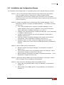
1.1
Key Features........................................................................................................................................................... 12
1.2
RAID Concepts ...................................................................................................................................................... 13
1.3
Disk Drive Organization .................................................................................................................................... 17
1.3.1
Physical Drive Groups................................................................................................................................ 17
1.3.2
Logical Unit Number (LUN) .................................................................................................................... 17
1.3.3
Hot Swap Drive Replacement ................................................................................................................ 17
1.3.4
Disk Failure Detection ............................................................................................................................... 17
1.4
Array Definition..................................................................................................................................................... 18
1.4.1
Array ................................................................................................................................................................. 18
1.4.2
Volume ............................................................................................................................................................ 18
Chapter 2
Installation Overview...............................................................................19
2.1
Packaging, Shipment and Delivery ............................................................................................................... 19
2.2
Unpacking the NAS System............................................................................................................................. 19
2.3
Identifying Parts of the NAS System ........................................................................................................... 20
2.3.1
Front View ...................................................................................................................................................... 20
2.3.2
Rear View........................................................................................................................................................ 20
2.3.3
LCD Display Panel....................................................................................................................................... 22
2.3.3.1
LCD Display Panel LEDs................................................................................................................... 22
2.3.3.2
LCD Front Panel Function Keys .................................................................................................... 23
Chapter 3
Getting Started with the NAS System.................................................24
3.1
Connecting the NAS to your Network........................................................................................................ 24
3.2
Powering On .......................................................................................................................................................... 24
3.3
Installing Hard Drives ......................................................................................................................................... 25
3.3.1
Drive Carrier Module ................................................................................................................................. 27
3.3.2
Disk Drive Status Indicator...................................................................................................................... 27
3.3.3
Lock Indicator ............................................................................................................................................... 28
2
User Manual
NAS System
Chapter 4
4.1
RAID Configuration Utility Options .....................................................29
Configuration through Terminal .................................................................................................................... 29
4.1.1
Upgrading Firmware through VT-100 Terminal Emulation ....................................................... 34
4.2
Configuration through the LCD Panel......................................................................................................... 36
4.3
Configuration through proRAID Manager GUI........................................................................................ 38
4.3.1
Login to proRAID Manager..................................................................................................................... 38
4.3.2
The ProRAID Manager Main Menu ..................................................................................................... 39
4.3.3
ProRAID Manager Menu Hierarchy ..................................................................................................... 42
Chapter 5
RAID Management...................................................................................43
5.1
Quick Setup ............................................................................................................................................................ 43
5.2
Create Array............................................................................................................................................................ 46
5.3
Modify Array .......................................................................................................................................................... 49
5.4
Delete Array............................................................................................................................................................ 50
5.5
Create Volume....................................................................................................................................................... 51
5.6
Modify Volume ..................................................................................................................................................... 54
5.7
Delete Volume....................................................................................................................................................... 55
Chapter 6
6.1
Network and System Management .....................................................56
Network Management ....................................................................................................................................... 56
6.1.1
Network Settings......................................................................................................................................... 56
6.1.2
SNMP Setting................................................................................................................................................ 57
6.1.3
SMTP Setting................................................................................................................................................. 58
6.1.4
NTP Setting.................................................................................................................................................... 59
6.1.5
Sync RTC ......................................................................................................................................................... 60
6.2
System Management.......................................................................................................................................... 61
6.2.1
System Setting.............................................................................................................................................. 61
6.2.2
Channel Manager........................................................................................................................................ 63
6.2.3
Modify Password ......................................................................................................................................... 65
6.2.4
Upgrade Firmware ...................................................................................................................................... 66
6.2.5
Restart.............................................................................................................................................................. 68
Chapter 7
7.1
Other proRAID Manager Menu Functions..........................................69
Event Log................................................................................................................................................................. 69
7.1.1
Event Log........................................................................................................................................................ 69
7.1.2
Export Log...................................................................................................................................................... 70
7.2
Information ............................................................................................................................................................. 71
7.2.1
Disk Information .......................................................................................................................................... 71
7.2.2
RAID Information......................................................................................................................................... 72
7.2.3
System Information .................................................................................................................................... 73
7.2.4
Hardware Monitor....................................................................................................................................... 74
User Manual
3
NAS System
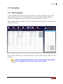
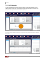
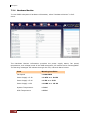
7.3
Raid Task.................................................................................................................................................................. 75
7.3.1
7.4
Raid Status ..................................................................................................................................................... 75
S.M.A.R.T. ................................................................................................................................................................. 77
7.4.1
Disk Health..................................................................................................................................................... 77
7.4.2
Diagnosis Disk .............................................................................................................................................. 78
PART II
proNAS System .............................................................................................79
Chapter 8
Introduction...............................................................................................80
8.1
proNAS Key Components................................................................................................................................. 80
8.2
Installation and Configuration Phases......................................................................................................... 81
8.3
Basic Setup Instructions in Creating Array and Volume...................................................................... 82
8.4
Setting proNAS IP Address and Connection to Management GUI ................................................ 85
Chapter 9
9.1
proNAS Manager......................................................................................87
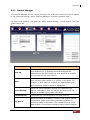
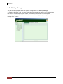
Volume Manager.................................................................................................................................................. 88
9.1.1
9.1.1.1
Create the proNASVG Volume Group....................................................................................... 89
9.1.1.2
Create another Volume Group ..................................................................................................... 92
9.1.1.3
Reset and Remove Volume Group ............................................................................................. 95
9.1.2
Logical Volume Configuration ............................................................................................................... 97
9.1.2.1
Create new Logical Volume ........................................................................................................... 97
9.1.2.2
Extending Logical Volume Size .................................................................................................... 99
9.1.3
Volume Snapshot......................................................................................................................................101
9.1.3.1
Create Snapshots Manually..........................................................................................................102
9.1.3.2
Create Snapshots Based from Schedule.................................................................................104
9.1.3.3
Delete Snapshots..............................................................................................................................107
9.1.4
Volume Replication ..................................................................................................................................109
9.1.4.1
Replication Configuration .............................................................................................................110
9.1.4.2
Checking the status of your replication .................................................................................115
9.1.4.3
Extending logical volume under replication .........................................................................116
9.1.5
9.2
Volume Group Management ................................................................................................................. 89
iSCSI ................................................................................................................................................................117
9.1.5.1
iSCSI Configuration..........................................................................................................................117
9.1.5.2
Disable iSCSI in Logical Volume ................................................................................................120
9.1.5.3
Restore iSCSI to Ordinary Logical Volume ............................................................................121
9.1.5.4
Extending iSCSI Logical Volume Size.......................................................................................123
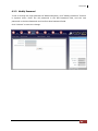
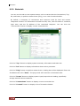
Network Manager..............................................................................................................................................125
9.2.1
Network Setting and Trunking ............................................................................................................125
9.2.2
Internet Gateway .......................................................................................................................................129
9.2.3
SNMP/MRTG ...............................................................................................................................................130
9.2.4
Network Test...............................................................................................................................................131
4
User Manual
NAS System
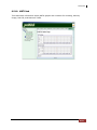
9.3
Account Manager...............................................................................................................................................132
9.3.1
9.3.1.1
Windows Authentication ...............................................................................................................132
9.3.1.2
Sample Steps to Join the NAS to Windows AD Domain: ...............................................133
9.3.1.3
NIS Authentication...........................................................................................................................135
9.3.1.4
Sample Steps to Join NIS Domain:...........................................................................................135
9.3.2
9.4
External Accounts Integration (Joining Windows or NIS Domain).......................................132
Local Account and Group Management .........................................................................................136
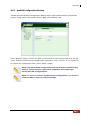
Share Manager....................................................................................................................................................144
9.4.1
Share Management ..................................................................................................................................145
9.4.1.1
Creating a New Share ....................................................................................................................145
9.4.1.2
Applying ACL......................................................................................................................................146
9.4.1.3
Modifying a Share............................................................................................................................146
9.4.1.4
Deleting a Share ...............................................................................................................................147
9.4.2
Properties Setting......................................................................................................................................148
9.4.3
Protocol Setting .........................................................................................................................................149
9.4.3.1
CIFS ........................................................................................................................................................149
9.4.3.2
NFS .........................................................................................................................................................150
9.4.3.3
AppleTalk .............................................................................................................................................150
9.4.3.4
Novell ....................................................................................................................................................150
9.4.4
Privilege Setting.........................................................................................................................................152
9.4.4.1
Group ....................................................................................................................................................152
9.4.4.2
Account.................................................................................................................................................153
9.4.4.3
IP Address............................................................................................................................................155
9.4.5
Rsync ..............................................................................................................................................................157
9.4.6
Duplication...................................................................................................................................................162
9.4.7
Default Share ..............................................................................................................................................166
9.5
System Manager.................................................................................................................................................167
9.5.1
Information tab ..........................................................................................................................................168
9.5.2
Upgrade tab ................................................................................................................................................169
9.5.3
Report tab ....................................................................................................................................................170
9.5.4
Time tab ........................................................................................................................................................171
9.5.5
Serial Ports tab...........................................................................................................................................172
9.5.6
Power tab .....................................................................................................................................................173
9.5.7
Reboot tab ...................................................................................................................................................174
9.5.8
Service tab....................................................................................................................................................175
9.5.9
Status tab .....................................................................................................................................................178
9.5.10
MRTG tab...................................................................................................................................................179
9.6
Backup Manager ...............................................................................................................................................180
9.6.1
proNAS Configuration Backup ............................................................................................................181
9.6.2
Configure Backup Plan............................................................................................................................182
User Manual
5
NAS System
9.6.3
Tape Control................................................................................................................................................187
9.6.3.1
Backup and Restore Using Tape................................................................................................188
9.7
Log Manager........................................................................................................................................................204
9.8
Event Manager ....................................................................................................................................................205
9.8.1
E-mail Setting tab .....................................................................................................................................205
9.8.2
Event Setting tab.......................................................................................................................................206
Chapter 10
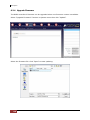
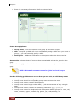
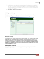
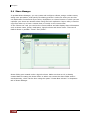
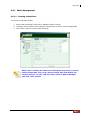
File Manager ........................................................................................ 207
10.1
Introduction to File Manager .....................................................................................................................207
10.2
Logon to File Manager..................................................................................................................................209
10.3
Directory and Upload Function .................................................................................................................210
10.4
User Access Right and Group Access Right.........................................................................................212
10.5
Change Password and Logout ...................................................................................................................212
Chapter 11
proBackup............................................................................................. 213
11.1
Introduction to proBackup ..........................................................................................................................213
11.2
Administrator Logon ......................................................................................................................................213
11.3
Create Backup Plan.........................................................................................................................................216
11.4
Restore Backup.................................................................................................................................................222
11.5
Account Detail ..................................................................................................................................................223
Chapter 12
proNAS HA (Optional Function)...................................................... 224
12.1
Introduction to proNAS HA ........................................................................................................................224
12.2
Getting Started with proNAS HA..............................................................................................................225
12.2.1
Hardware Aspect.....................................................................................................................................226
12.2.2
Procedure for Setting Up proNAS HA...........................................................................................227
12.3
ProNAS HA Properties...................................................................................................................................236
12.4
Extending a Logical Volume in HA ..........................................................................................................237
12.5
Clear All HA Configuration ..........................................................................................................................238
12.6
License Registration........................................................................................................................................240
12.7
Event Log Properties ......................................................................................................................................241
6
User Manual
NAS System
Preface
About this manual
This manual provides information regarding the quick installation and hardware
features of the NAS System. This document also describes how to use the storage
management software. Information contained in the manual has been reviewed for
accuracy, but not for product warranty because of the various
environment/OS/settings. Information and specifications will be changed without
further notice.
This manual uses section numbering for every topics being discussed for easy and
convenient way of finding information in accordance with the user’s needs. The
following icons are being used for some details and information to be considered in
going through with this manual:
NOTES:
These are notes that contain useful information and tips
that the user must give attention to in going through
with the subsystem operation.
IMPORTANT!
These are the important information that the user must
remember.
WARNING!
These are the warnings that the user must follow to avoid
unnecessary errors and bodily injury during hardware and
software operation of the subsystem.
CAUTION:
These are the cautions that user must be aware of to
prevent damage to the equipment and its components.
Copyright
No part of this publication may be reproduced, stored in a retrieval system, or
transmitted in any form or by any means, electronic, mechanical, photocopying,
recording or otherwise, without the prior written consent.
Trademarks
All products and trade names used in this document are trademarks or registered
trademarks of their respective owners.
Changes
The material in this document is for information only and is subject to change without
notice.
NOTE: Some screenshots may be different from actual NAS system.
User Manual
7
NAS System
FCC Compliance Statement
This equipment has been tested and found to comply with the limits for a Class B digital
device, pursuant to Part 15 of the FCC rules. These limits are designed to provide
reasonable protection against harmful interference in residential installations. This
equipment generates, uses, and can radiate radio frequency energy, and if not installed
and used in accordance with the instructions, may cause harmful interference to radio
communications.
However, there is not guarantee that interference will not occur in a particular
installation. If this equipment does cause interference to radio or television equipment
reception, which can be determined by turning the equipment off and on, the user is
encouraged to try to correct the interference by one or more of the following measures:
1. Reorient or relocate the receiving antenna
2. Move the equipment away from the receiver
3. Plug the equipment into an outlet on a circuit different from that to which the
receiver is powered.
4. Consult the dealer or an experienced radio/television technician for help
All external connections should be made using shielded cables
8
User Manual
NAS System
Before You Begin
Before going through with this manual, you should read and focus to the following
safety guidelines. Notes about the subsystem’s controller configuration and the
product packaging and delivery are also included.
Safety Guidelines
To provide reasonable protection against any harm on the part of the user and to
obtain maximum performance, user is advised to be aware of the following safety
guidelines particularly in handling hardware components:
Upon receiving of the product:
Place the product in its proper location.
To avoid unnecessary dropping out, make sure that somebody is around for
immediate assistance.
It should be handled with care to avoid dropping that may cause damage to the
product. Always use the correct lifting procedures.
Upon installing of the product:
Ambient temperature is very important for the installation site. It must not
exceed 30°C. Due to seasonal climate changes; regulate the installation site
temperature making it not to exceed the allowed ambient temperature.
Before plugging-in any power cords, cables and connectors, make sure that the
power switches are turned off. Disconnect first any power connection if the power
supply module is being removed from the enclosure.
Outlets must be accessible to the equipment.
All external connections should be made using shielded cables and as much as
possible should not be performed by bare hand. Using anti-static hand gloves is
recommended.
In installing each component, secure all the mounting screws and locks. Make
sure that all screws are fully tightened. Follow correctly all the listed procedures
in this manual for reliable performance.
Controller Configuration
This NAS system supports single RAID controller configuration.
Packaging, Shipment and Delivery
Before removing the subsystem from the shipping carton, you should visually
inspect the physical condition of the shipping carton.
Unpack and verify that the contents of the shipping carton are complete and in
good condition.
Exterior damage to the shipping carton may indicate that the contents of the
carton are damaged.
If any damage is found, do not remove the components; contact the dealer where
you purchased the subsystem for further instructions.
User Manual
9
NAS System
PART I Hardware Components and RAID Subsystem
10
User Manual
NAS System
Chapter 1 Introduction
The NAS System
Companies are looking for cost-effective storage solutions which can offer the best
performance, high scalability and reliability. As the number of users and the amount of
data grows, Network Attached Storage is becoming a critical technology and the need for
an optimized solution is becoming an important requirement.
Proware delivers the Epica NAS system together with the proNAS management solution,
proNAS High-Availability and proBackup client backup solution to provide businesses
with the most flexible, scalable, securable and manageable NAS environment. It helps to
control the total cost of ownership for data management.
The NAS system is an SATA II NAS Subsystem with proNAS 1.1 operating system. It
enhances system availability, and manages complex storage environments easily. For
improving business productivity and minimizing business risks, the NAS system provides
a volume replication and a volume snapshot function. It is also a full featured data
protection system supporting RAID levels 0, 1, 0+1, 3, 5, 6, 30, 50, Linear and JBOD. It
supports hot spares and automatic hot rebuild.
User Manual
11
NAS System
1.1 Key Features
Configurable to 19" rack-mountable 2U chassis
Supports up to Twelve (12) 1" hot - swappable SATA II hard drives
Supports Tape/DAT backup/restore
Supports RAID levels 0, 1, 0+1, 3, 5, 6, 30, 50, Linear and JBOD
Smart-function LCD panel for RAID setting & ENC status
Supports hot spare and automatic hot rebuild
Two Gigabit, One 10/100Mb Ethernet ports
Linux-based embedded system(128MB Disk on Module)
Centralization of Data and Storage Management
Using Market-Leading Java Technology
Latest volume snapshot technology
Apply volume replication to enhance data protection
Support logical volume over 2TB
Data Backup via backup plan and scheduling
Enhance system configuration backup
Local and external account management
Large account import
Share management and permission
Advance ACL setting for project share
Support Internet Gateway function
On-line expansion file system
Support E-mail notification and system log information
Multi application support via proFamily
12
User Manual
NAS System
1.2 RAID Concepts
RAID Fundamentals
The basic idea of RAID (Redundant Array of Independent Disks) is to combine multiple
inexpensive disk drives into an array of disk drives to obtain performance, capacity and
reliability that exceeds that of a single large drive. The array of drives appears to the
host computer as a single logical drive.
Five types of array architectures, RAID 1 through RAID 5, were originally defined; each
provides disk fault-tolerance with different compromises in features and performance. In
addition to these five redundant array architectures, it has become popular to refer to a
non-redundant array of disk drives as a RAID 0 arrays.
Disk Striping
Fundamental to RAID technology is striping. This is a method of combining multiple
drives into one logical storage unit. Striping partitions the storage space of each drive
into stripes, which can be as small as one sector (512 bytes) or as large as several
megabytes. These stripes are then interleaved in a rotating sequence, so that the
combined space is composed alternately of stripes from each drive. The specific type of
operating environment determines whether large or small stripes should be used.
Most operating systems today support concurrent disk I/O operations across multiple
drives. However, in order to maximize throughput for the disk subsystem, the I/O load
must be balanced across all the drives so that each drive can be kept busy as much as
possible. In a multiple drive system without striping, the disk I/O load is never perfectly
balanced. Some drives will contain data files that are frequently accessed and some
drives will rarely be accessed.
By striping the drives in the array with stripes large enough so that each record falls
entirely within one stripe, most records can be evenly distributed across all drives. This
keeps all drives in the array busy during heavy load situations. This situation allows all
drives to work concurrently on different I/O operations, and thus maximize the number
of simultaneous I/O operations that can be performed by the array.
User Manual
13
NAS System
Definition of RAID Levels
RAID 0 is typically defined as a group of
striped disk drives without parity or data
redundancy. RAID 0 arrays can be configured
with large stripes for multi-user environments
or small stripes for single-user systems that
access long sequential records. RAID 0 arrays
deliver the best data storage efficiency and
performance of any array type. The
disadvantage is that if one drive in a RAID 0
array fails, the entire array fails.
RAID 1, also known as disk mirroring, is
simply a pair of disk drives that store
duplicate data but appear to the computer as
a single drive. Although striping is not used
within a single mirrored drive pair, multiple
RAID 1 arrays can be striped together to
create a single large array consisting of pairs
of mirrored drives. All writes must go to both
drives of a mirrored pair so that the
information on the drives is kept identical.
However, each individual drive can perform
simultaneous, independent read operations.
Mirroring thus doubles the read performance
of a single non-mirrored drive and while the
write performance is unchanged. RAID 1 delivers the best performance of any redundant
array type. In addition, there is less performance degradation during drive failure than in
RAID 5 arrays.
RAID 3 sector-stripes data across groups of
drives, but one drive in the group is dedicated
to storing parity information. RAID 3 relies on
the embedded ECC in each sector for error
detection. In the case of drive failure, data
recovery is accomplished by calculating the
exclusive OR (XOR) of the information
recorded on the remaining drives. Records
typically span all drives, which optimizes the
disk transfer rate. Because each I/O request
accesses every drive in the array, RAID 3
arrays can satisfy only one I/O request at a
time. RAID 3 delivers the best performance
for single-user, single-tasking environments
with long records. Synchronized-spindle drives are required for RAID 3 arrays in order to
avoid performance degradation with short records. RAID 5 arrays with small stripes can
yield similar performance to RAID 3 arrays.
14
User Manual
NAS System
Under RAID 5 parity information is distributed
across all the drives. Since there is no dedicated
parity drive, all drives contain data and read
operations can be overlapped on every drive in the
array. Write operations will typically access one
data drive and one parity drive. However, because
different records store their parity on different
drives, write operations can usually be overlapped.
RAID 6 is similar to RAID 5 in that data protection is achieved by writing parity
information to the physical drives in the array. With RAID 6, however, two sets of parity
data are used. These two sets are different, and each set occupies a capacity equivalent
to that of one of the constituent drives. The main advantage of RAID 6 is High data
availability – any two drives can fail without loss of critical data.
Dual-level RAID achieves a balance between the increased data availability inherent in
RAID 1, RAID 3, or RAID 5, and the increased read performance inherent in disk striping
(RAID 0). These arrays are sometimes referred to as RAID 0+1, RAID 30, or RAID 50.
User Manual
15
NAS System
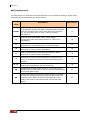
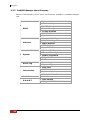
RAID Management
The subsystem can implement several different levels of RAID technology. RAID levels
supported by the subsystem are shown below.
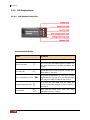
RAID
Description
Min. Drives
Linear is similar to RAID 0 in that it combines the capacity
of all member drives. The data is written linearly starting
with the first disk drive. When first disk drive becomes
full, the next disk drive is used. There is no data
redundancy.
1
0
Block striping is provided, which yields higher
performance than with individual drives. There is no
redundancy.
2
1
Drives are paired and mirrored. All data is 100%
duplicated on an equivalent drive. Fully redundant.
2
3
Data is striped across several physical drives. Parity
protection is used for data redundancy.
3
5
Data is striped across several physical drives. Parity
protection is used for data redundancy.
3
6
Data is striped across several physical drives. Parity
protection is used for data redundancy. Requires N+2
drives to implement because of two-dimensional parity
scheme.
4
0+1
Combination of RAID levels 0 and 1. This level provides
striping and redundancy through mirroring.
4
30
Combination of RAID levels 0 and 3. This level is best
implemented on two RAID 3 disk arrays with data striped
across both disk arrays.
6
50
RAID 50 provides the features of both RAID 0 and RAID
5. RAID 50 includes both parity and disk striping across
multiple drives. RAID 50 is best implemented on two
RAID 5 disk arrays with data striped across both disk
arrays.
6
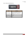
Level
Linear
16
User Manual
NAS System
1.3 Disk Drive Organization
The RAID subsystem arranges the disk drives connected to it as a physical drive group
and logical unit (LUN).
1.3.1 Physical Drive Groups
The subsystem has up to a maximum of twelve (12) individual disk drives which can be
used to form a physical drive group. To calculate the total size of a particular drive group,
(Smallest disk size) x (Number of disk) = Capacity for RAID 0
(Smallest disk size) x [(Number of disk) / 2] = Capacity for RAID 1
(Smallest disk size) x [(Number of disk) - 1] = Capacity for RAID 3 or 5
{(Smallest disk size) x [(Number of disks in each sub-array) - 1)]} x (Number of subarrays) = Capacity for RAID 30 or 50
1.3.2 Logical Unit Number (LUN)
A logical unit is a drive group read by the host system as a logical device. The subsystem
supports up to eight (8) LUNs for drive group.
1.3.3 Hot Swap Drive Replacement
The subsystem supports hot-swapping of drives while the system is powered on. A disk
may be disconnected, removed or replaced with a different disk without turning off the
system.
1.3.4 Disk Failure Detection
The subsystem can automatically detect disk failures. It monitors disk activities including
the elapsed time on all commands issued to the disks as well as parity errors and other
potential problems. A time-out will reset the disk and retry the command. If the
command time-out occurs again, the disk will fail. Any disk with too many errors will be
shut down by subsystem.
User Manual
17
NAS System
1.4 Array Definition
1.4.1 Array
An Array is a group of physical disks (disk drives) containing one or more Volumes.
When an Array is created, the RAID Level is assigned. RAID Level refers to the level of
data performance and protection of an Array.
It is impossible to have multiple Arrays on the same physical disks. If physical disks of
different capacity are grouped together in an Array, then the capacity of the smallest
disk will become the effective capacity of all the disks in the Array.
1.4.2 Volume
A Volume is seen by the host system as a single logical device. A Volume must be
created on an Array. If there is an existing Array and there is available free raw
capacity, then a new Volume can still be created.
A Volume capacity can consume all or a portion of the capacity available in an
Array. Multiple Volumes can exist on a group of disks in an Array. Additional
Volumes created in an Array will reside on all the physical disks in the Array. Thus
each Volume on the Array will have its data spread evenly across all the disks in
the Array.
18
User Manual
NAS System
Chapter 2 Installation Overview
2.1 Packaging, Shipment and Delivery
Before removing the subsystem from the shipping carton, you should visually
inspect the physical condition of the shipping carton.
Unpack and verify that the contents of the shipping carton are complete and in
good condition.
Exterior damage to the shipping carton may indicate that the contents of the
carton are damaged.
If any damage is found, do not remove the components; contact the dealer where
you purchased the subsystem for further instructions.
2.2 Unpacking the NAS System
The package contains the following items:
• NAS system unit
• Two (2) power cords
• Two (2) external SCSI cables
• Three (3) Ethernet LAN cables
• One (1) external serial cable (phone-jack to DB9)
• One (1) external UPS cable (phone-jack to DB9)
• Installation Reference Guide
• Spare screws, etc.
If any of these items are missing or damaged, please contact your dealer or sale
representative for assistance.
User Manual
19
NAS System
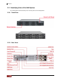
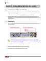
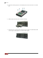
2.3 Identifying Parts of the NAS System
The illustrations below identify the various parts of the subsystem.
2.3.1 Front View
2.3.2 Rear View
20
User Manual
NAS System
1. Power Alarm Reset Button – You can push the power supply alarm reset
button to stop the power supply buzzer alarm.
2. Monitor Port – The system is equipped with a serial monitor port allowing you to
connect a PC or terminal.
3. Uninterrupted Power Supply (UPS) Port – The system comes with an optional
UPS port allowing you to connect a UPS (dumb mode UPS) device. Connect the
cable from the UPS device to the UPS port located at the rear of the system. To
connect the NAS to a smart mode UPS, use the serial port instead and configure
the options in Section 9.5.5.
4. Host Channel B – Connect to Host’s SCSI adapter or other devices. This enables
another host to use the RAID function and detect a RAID volume from the NAS.
5. R-Link Port – The subsystem is equipped with one 10/100 Ethernet RJ45LAN
port. You use web-based browser to management RAID system through Ethernet
for remote configuration and monitoring.
6. Power Supply Unit A-B – Two power supplies (PSU-A and PSU-B) are located at
the rear of the NAS system. Turn on the power of these power supplies to poweron the NAS. The “Power” LED at the front panel will turn green.
If the power supply fails to function or a power supply was not turned on, the
Power Fail LED will turn red and an alarm will sound. An error message will
also appear on the LCD screen warning of power failure. Press the Power Supply
Alarm Reset button at the rear to stop the alarm.
User Manual
21
NAS System
2.3.3 LCD Display Panel
2.3.3.1 LCD Display Panel LEDs
Environmental Status
Parts
Function
Power LED
Green indicates power is ON.
Power Fail LED
If one of the redundant power supply unit
fail, this LED will turn to RED and alarm will
sound.
Fan Fail LED
Turns RED when a fan’s speed is lower than
2000 RPM or fan fails.
Over Temperature LED
If system temperature is over 70oC or disk
temperatures exceed 55oC the temperature
LED will turn RED and alarm will sound.
Voltage Warning LED
This LED will turn RED and an alarm will
sound if detected voltage in the controller is
abnormal.
Access LED
This LED will blink blue when the RAID
controller is busy / active.
22
User Manual
NAS System
2.3.3.2 LCD Front Panel Function Keys
Parts
Functions
Up and Down
Arrow buttons
Use the Up or Down arrow keys to go
through the information on the LCD
screen. This is also used to move between
each menu when you configure the
subsystem.
Select button
This is used to enter the option you have
selected.
Exit button
EXIT
Press this button to return to the previous
menu.
User Manual
23
NAS System
Chapter 3 Getting Started with the NAS System
3.1 Connecting the NAS to your Network
1. Attach network cable to the R-Link port. Connect the other end to your network
hub or switch. Alternatively, you may use the Monitor port and connect the serial
cable (phone-jack to DB9) from the Monitor port to the COM port of the host /
server that will be used to manage the RAID controller of the NAS.
2. Attach network cable to the Ethernet port eth0. Connect the other end to your
network hub or switch. You may also connect the other Ethernet ports eth1 and
eth2 if needed.
3.2 Powering On
1. Plug in all the power cords into the AC Power Input Socket located at the rear of
the NAS system.
NOTE: The NAS system is equipped with redundant, full range
power supplies with PFC (power factor correction). The system will
automatically select voltage.
2. Open the protective cover of the System Power Switch.
3. Press the System Power Switch to power on the NAS.
4. The Power LED on the front Panel will turn green.
24
User Manual
NAS System
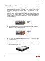
3.3 Installing Hard Drives
This section describes the physical locations of the hard drives supported by the
NAS system and give instructions on installing a hard drive. The system supports
hot-swapping allowing you to install or replace a hard drive while the NAS is
running.
Each Drive Carrier has a locking mechanism. When the Lock Groove is horizontal,
this indicates that the Drive Carrier is locked. When the Lock Groove is vertical,
then the Drive Carrier is unlocked. Lock and unlock the Drive Carriers by using a
flat-head screw driver.
Carrier
Lock
Indicator
a.
The Lock Grooves are located on the carrier open button. Press the button
and the Drive Carrier handle will flip open.
Carrier
Open
Button
b.
Pull out an empty disk tray. Pull the handle outwards to remove the carrier
from the enclosure.
c. Place the hard drive in the disk tray. Make sure the holes of the disk tray align
with the holes of the hard drive.
User Manual
25
NAS System
d. Install the mounting screws on the bottom part to secure the drive in the disk
tray.
e.
Slide the tray into a slot until it reaches a full stop.
f.
Press the lever in until you hear the latch click into place. The HDD status LED
will turn green if NAS system is on and the HDD is good.
26
User Manual
NAS System
3.3.1 Drive Carrier Module
The Drive Carrier Module houses a 3.5 inch hard disk drive. It is designed for
maximum airflow and incorporates a carrier locking mechanism to prevent
unauthorized access to the HDD.
3.3.2 Disk Drive Status Indicator
Every Drive Carrier has 2 status indicator lights. One indicator light is used for
Power On/Error. When this light is GREEN the power is on and everything is
functioning normally. When the Power On/Error light is ORANGE, then an error has
occur that requires the user’s attention.
The other status indicator light is the hard disk drive activity light. When the hard
disk drive is being accessed, this light will flash BLUE.
In addition, both indicator lights are viewable within a 170° arc.
Status Light
Indicator
Disk
Activity
Indicator
Disk Status
Indicator
User Manual
27
NAS System
3.3.3 Lock Indicator
Every Drive Carrier is lockable and is fitted with a lock indicator to indicate whether
or not the carrier is locked into the chassis or not. Each carrier is also fitted with an
ergonomic handle for easy carrier removal.
Drive Carrier
is Unlocked
Drive
Carrier is
locked
28
User Manual
NAS System
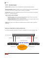
Chapter 4 RAID Configuration Utility Options
The RAID controller in the NAS system has a built-in setup configuration utility
containing important information about the configuration as well as settings for various
optional functions in the subsystem. This chapter explains how to use and make changes
to the setup utility.
Configuration Methods
There are three methods of configuring the RAID controller:
• VT100 terminal connected through the controller’s serial port
• Front panel touch-control keypad
• Web browser-based proRAID Manager GUI
IMPORTANT: Only one method can be used to configure the RAID
subsystem. Two methods can be used at the same time but the
other method will be in read-only mode.
4.1 Configuration through Terminal
To start-up:
1. Connect a VT100 compatible terminal or a PC operating in an equivalent terminal
emulation mode to the monitor port located at the rear of the subsystem.
NOTE: You may connect a terminal while the subsystem’s power is
on.
2. Power-on the terminal.
3. Run the VT100 program or an equivalent terminal program.
User Manual
29
NAS System
4. The default setting of the monitor port is 115200 baud rate, 8 data bit, non-parity, 1
stop bit and no flow control.
30
User Manual
NAS System
5. After connecting and powering on the terminal. Press “l” key to enter password
screen. The preset password is 8 zeroes. Type “00000000”.
6. Then press <Enter> to enter screen. The Main Menu will appear.
Keyboard Function Key Definitions
“Enter” key: to confirm a selected item
“<Ctrl> + Q” key: to exit a selection or Logout
“
” Arrow keys: to move in / among fields or Traverse Menu
“Tab” key: to move to the next default value
User Manual
31
NAS System
VT100 terminal configuration Utility Main Menu Options
Select an option and the related information or submenu items display beneath it. The
submenus for each item are listed below.
32
User Manual
NAS System
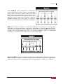
The configuration utility main menu options are:
Menu Option
Description
Quick Setup
Quickly create a single Array and Volume
RAID Management
Create single or multiple Arrays and Volumes with
custom parameters.
SCSI Configuration
Set SCSI parameters such as SCSI ID, speed and
Tag Queue.
System Management
Set System parameters such as Ethernet, Time,
password, Upgrade Firmware and Event Logs
Disk Management
Set disk utility such as view disk status and set
faulty.
User Manual
33
NAS System
4.1.1 Upgrading Firmware through VT-100 Terminal Emulation
The RAID controller’s firmware can be upgraded through a terminal.
To upgrade the firmware, follow these steps:
1. Shut down the host computer system, if a host computer is connected.
2. Start a terminal connection to the disk array and access the Menu area.
3. From the Main Menu, scroll down to “System Management”
4. Choose the “Upgrade Firmware”. The Upgrade the Raid Firmware dialog box
appears.
5. Press Enter to confirm. Go to the menu tool bar and select Transfer. Open Send
File.
34
User Manual
NAS System
6. Click Browse. Locate where the Firmware file has been saved, select the file and
click Open.
7. Select “Ymodem” under Protocol. YMODEM is the file transfer protocol used by the
terminal emulation software.
8. Click “Send” to send the Firmware file to the RAID controller.
9. When Firmware download is completed, the subsystem will restart. Need to login
again to terminal after restart.
User Manual
35
NAS System
4.2 Configuration through the LCD Panel
All configurations can be performed through the LCD Display front panel function keys,
except for the “Firmware update”. The LCD provides a system of screens with areas for
information, status indication, or menus. The LCD screen displays menu items or other
information up to two lines at a time. The RAID subsystem password is set to 00000000
by manufacture default.
Function Key Definitions
Parts
Function
Exit button
Press this button to return to the previous menu.
Select button
This is used to enter the option you have selected.
Up and Down
arrow buttons
Use the Up or Down arrow keys to move between
each menu when you configure the subsystem.
The following tree diagram is a summary of the various configurations and setting
functions that can be accessed through the LCD panel menus. Press the Select button
and enter the password to access the menu functions.
36
User Manual
NAS System
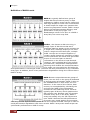
To view system information, hardware monitor information, array information, and other
related information, press the Down Arrow button.
NAS-Model-Name
RAID READY
IOP-80331 FW1.30
RAM:256MB HD#12
Temperature
System:40 C
S 1:34C S 2:31C
S 3:33C S 4:32C
S 5:33C S 6:29C
S 7:29C S 8:31C
S 9:32C S10:31C
S11:32C S12:31C
MF/PSU-A: 3214rpm
MF/PSU-B: 3213rpm
Array1
IN USE ARRAY >
A: 899G Fr:399G
Level: RAID 5
Stripe Size:128K
Block Size:512 byte
Member disks:
1234
Disk Info
Disks: 12
Vol1
Size: 499.9 GB
>
(shows hard disk info, such as model, capacity)
User Manual
37
NAS System
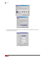
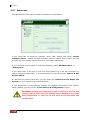
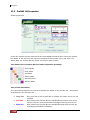
4.3 Configuration through proRAID Manager GUI
The RAID subsystem can be managed through the controller’s Ethernet connection.
Any PC on the network to which the RAID subsystem is connected can manage the
subsystem using proRAID Manager. proRAID Manager is web browser-based
Graphical User Interface (GUI) that is supported on many OS platforms.
This chapter describes the steps that you need to start up ProRAID Manager and
how to use it on your system.
NOTE: Flash Player 10 or later version must be installed in the PC
which will be used to manage the RAID subsystem.
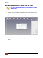
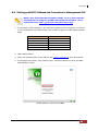
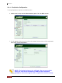
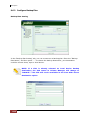
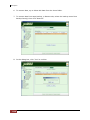
4.3.1 Login to proRAID Manager
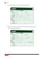
Open a web browser and enter http://xxx.xxx.xxx.xxx, where xxx.xxx.xxx.xxx is the IP
address of the RAID subsystem. The Login screen will be displayed.
Enter the subsystem name (you can use any name to identify the subsystem you are
going to manage) and the password.
NOTE: The default IP address of the RAID system is 172.16.0.2.
The IP address can be verified from LCD panel; select System
Config and then Ethernet Config. The default subsystem password
is 00000000.
NOTE: The session timeout limit is 10 minutes. When the GUI is
not used within 10 minutes, user will be logged out automatically.
38
User Manual
NAS System
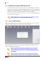
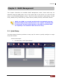
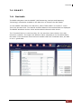
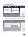
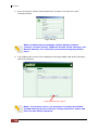
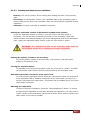
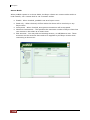
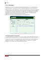
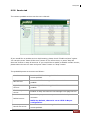
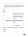
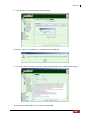
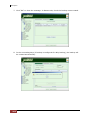
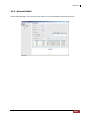
4.3.2 The ProRAID Manager Main Menu
After login, the Main Screen will be displayed. There are several menu items shown on
the upper part of the screen. The menu items are grouped according to their
functionality.
Each menu item can have several sub-menu items. Click the icon of the menu item and
the sub-menu will be displayed.
The right pane shows the list of subsystems that you have logged in to. You can login to
several subsystems at a time using a single proRAID Manager GUI.
to show or hide the proRAID Manager
On the left side of the screen is an icon
Menu hierarchy. The menu hierarchy is a list form of the menu options available on the
upper part of the screen. It provides a quicker way to access the submenu items.
User Manual
39
NAS System
40
User Manual
NAS System
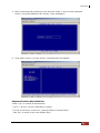
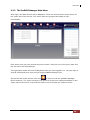
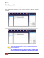
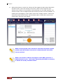
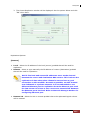
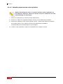
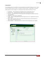
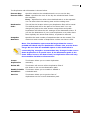
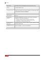
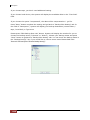
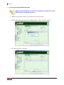
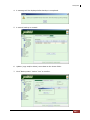
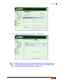
Mount or Detach RAID Subsystem
To login to another RAID Subsystem, click the Mount button and enter the subsystem
name (you can use any name to identify the subsystem you are going to manage), the
IP address, and the subsystem password. The subsystem name will appear in the list of
subsystem on the right screen.
To logout from a subsystem, select the subsystem name and click Detach. In the
confirmation screen, select OK to proceed with logout.
User Manual
41
NAS System
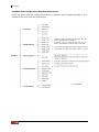
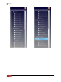
4.3.3 ProRAID Manager Menu Hierarchy
Below is the summary of the menu and functions available in proRAID Manager
GUI.
Quick Setup
Create Array
Modify Array
RAID
Delete Array
Create Volume
Modify Volume
Delete Volume
Network Setting
SNMP Setting
Network
SMTP Setting
NTP Setting
Sync RTC
System Setting
Channel Manager
System
Modify Password
Upgrade Firmware
Restart
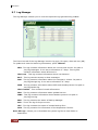
Event Log
Event Log
Export Log
Disk Info
Information
RAID
System Info
Hardware Monitor
Raid Task
S.M.A.R.T
42
User Manual
Raid Status
Disk Health
Diagnosis Disk
NAS System
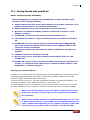
Chapter 5 RAID Management
This chapter describes the available RAID Management tasks; these tasks may be
selected using the RAID menu icon in the upper part of the screen or in the left side
menu of the ProRAID Manager screen. There are seven functions: Quick Setup, Create
Array, Modify Array, Delete Array, Create Volume, Modify Volume, and Delete Volume.
NOTE: Any FREE or un-used hard disk will automatically become
Global Hot Spare disk, which means it can replace any failed disk
in any Array, as long as the capacity is the same or greater than
the capacity of the smallest disk size in the Array.
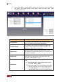
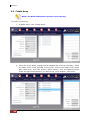
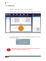
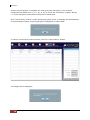
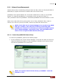
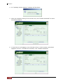
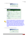
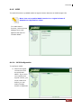
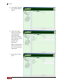
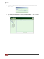
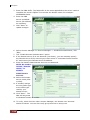
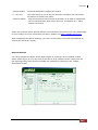
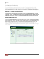
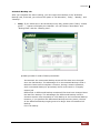
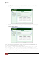
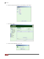
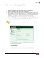
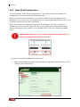
5.1 Quick Setup
The Quick Setup function provides an easy way for users to quickly configure a single
Array and Volume.
Here are the steps:
1.
In Raid menu, click “Quick Setup”.
User Manual
43
NAS System
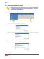
2.
Enter Array Name, Volume Name, select the disk drives to be included in
the Array, and select RAID Level, Stripe Size, and Block Size. Click
“Submit” when done.
Option
Description
Array Name
The name of the array you want to assign to the
Array. It should not exceed 20 characters.
Volume Name
The name of the volume you wan to assign to the
Volume. After mapping the Volume as LUN, it will
appear as a disk device to the host.
RAID Level
Select the RAID Level you want the Array to use.
The RAID level option will depend on the number of
disk drives selected.
Stripe Size
This parameter sets the size of the stripe written to
each disk. You can set the stripe size to 8k, 16k,
32k, 64k, 128k, 256k or 512k.
Use this option to enable creating Volume over
2TB.
Block Size
44
User Manual
For Windows OS, such as Windows 2000, 2003:
Use 1KB, 2KB or 4KB.
For 64bit LBA mode, such as Windows 2003+SP1
or later versions, Linux 2.6 or later versions:
Use 512 bytes. Due to LSI chip limitation,
16 Byte CDB option must run at U320 mode.
NAS System
3.
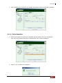
The Array and Volume will be created.
NOTE: Quick Setup can only be used if there’s no existing Array.
NOTE: In Quick Setup, the Array will be created in background
initialization mode, which means the Volume will be available
immediately while initializing in the background.
User Manual
45
NAS System
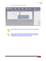
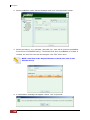
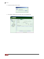
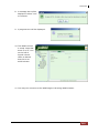
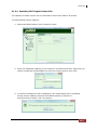
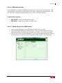
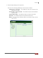
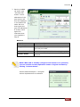
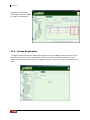
5.2 Create Array
NOTE: The RAID subsystem supports up to 8 Arrays.
To create a new Array:
1. In RAID menu, click “Create Array”.
2. Enter the Array Name, change the Re-Mapped BS count as necessary, select
the disks drives to be included in the Array, and set the RAID Level, Stripe
Size, Block Size, and Task Priority. Other options, such as Background Init
mode and Ignore Bad Sectors, can also be set. Click “Submit” when done.
46
User Manual
NAS System
Option
Description
Array Name
The name of the array you want to assign to the
Array. Maximum is 20 characters.
Capacity
The total capacity of the Array in GB.
Re-Mapped BS count
Set the maximum number of bad sector count to be
remapped. Default is 1000. Maximum number of
bad sector is 10,000.
RAID Level
Select the RAID Level you want the Array to use.
The RAID level option will depend on the number of
disk drives selected.
Stripe Size
This parameter sets the size of the stripe written to
each disk. You can set the stripe size to 8k, 16k,
32k, 64k, 128k, 256k or 512k.
Use this option to enable creating Volume over
2TB.
Block Size
For Windows OS, such as Windows 2000, 2003:
Use 1KB, 2KB or 4KB.
For 64bit LBA mode, such as Windows 2003+SP1
or later versions, Linux 2.6 or later versions:
Use 512 bytes. Due to LSI chip limitation,
16 Byte CDB option must run at U320 mode.
Task Priority
The priority for background tasks, such as
rebuilding. Options are: LOW, MEDIUM, and HIGH.
LOW priority means less system resources are
allotted to background task, and access to Array
and Volume is faster. In HIGH priority, more
system resources are used for background task,
and access to Array and Volume is slower.
Background Init
The default Array Initialization mode is Foreground
Init mode (the Background Init option is
unchecked) and Volume(s) can only be added to
the Array after initialization is completed. When
Background Init mode is used, the Array will be
accessible during initialization and Volume(s) can
be created immediately. Note that accessing the
Array during background initialization can have
performance impact.
Ignore Bad Sectors
Use this option to Ignore Bad Sectors. This option is
used when rescuing Array. It is recommended that
you disable this option in normal situation.
User Manual
47
NAS System
3. The Array will be initialized.
4. The next step is to create a Volume. When Array has completed its
initialization in Foreground mode, or still initializing in Background mode, a
Volume can created.
NOTE: Any FREE or un-used hard disk will automatically become
Global Hot Spare disk, which means it can replace any failed disk
in any Array, as long as the capacity is the same or greater than
the capacity of the smallest disk size in the Array.
48
User Manual
NAS System
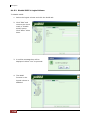
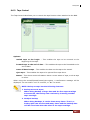
5.3 Modify Array
Use this function to modify settings of an existing Array
To modify Array:
1. In RAID menu, click “Modify Array”. Change the settings of the Array as
necessary.
NOTE: Some settings are read-only and cannot be modified.
2. Click “Submit” when done. The modified Array will be saved.
User Manual
49
NAS System
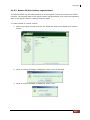
5.4 Delete Array
1. To delete an Array, select “Delete Array” from RAID menu.
2. Select the Array to be deleted from the list of Arrays displayed on the left side.
3. Click “Submit” when done. A warning message will be displayed. Click “OK” to
proceed with deletion.
IMPORTANT: Make sure that the data in the Array to be deleted is
no longer needed before deleting an Array.
50
User Manual
NAS System
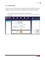
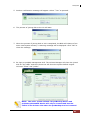
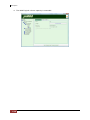
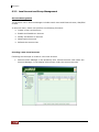
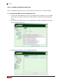
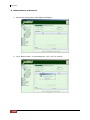
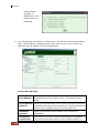
5.5 Create Volume
A Volume is seen by the host system as a single logical device. Multiple Volumes can be
created in an Array as long as there is free capacity in the Array. Up to 32 Volumes can
be mapped to a LUN in each Host Channel (LUN ID 0 to 31 for Host A and for Host B).
1. To create a Volume, select “Create Volume” from RAID menu.
2. From the list of Array in the left column, select the Array where the Volume will
be created.
User Manual
51
NAS System
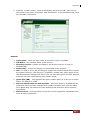
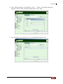
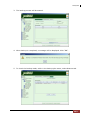
3. Enter the Volume Name, the Volume Size, and change the Read Ahead option if
necessary. Map the Volume to a LUN by enabling the Activate option and
selecting the LUN ID in the Host Channel.
Option
Description
Volume Name
The name you want to assign to the Volume.
Maximum is 20 characters.
Volume Size
The capacity you want to give to the Volume; value
is in GB. Note that the available capacity that can be
used in displayed in Maximum Capacity field.
Read Ahead
The Maximum number of Read Ahead is 99. The
controller will read ahead to optimize performance
on sequential reads.
Activate
Enable this option to activate the Volume in the
selected Host Channel (A and/or B).
Host A, Host B - LUN #
The LUN ID in the Host Channel assigned to the
Volume. Each Host Channel has 32 LUN IDs.
52
User Manual
NAS System
4. Click “Submit” when done. The Volume will be created.
IMPORTANT: Once a LUN number is already assigned to a Volume,
it cannot be used again.
User Manual
53
NAS System
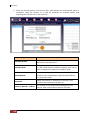
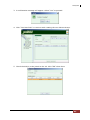
5.6 Modify Volume
The Volume attributes can be modified using the “Modify Volume” function in RAID menu.
To modify a Volume:
1. Select “Modify Volume” from RAID menu. Select the Array name from the Array
List, and then select the Volume to be modified.
2. Change the settings as necessary. Note that some settings cannot be modified.
3. Click “Submit” when done. The modified Volume settings is saved.
54
User Manual
NAS System
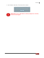
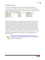
5.7 Delete Volume
To delete a Volume:
1. Select “Delete Volume” from RAID menu. From the Array List, select the Array
name which contains the Volume to be deleted. Then select the Volume to be
deleted.
2. Click “Submit”. A warning message will be displayed. Click “OK” to proceed.
3. The Volume will be deleted.
IMPORTANT: Make sure that the data in the Volume to be deleted
is no longer needed before deleting the Volume.
User Manual
55
NAS System
Chapter 6 Network and System Management
6.1 Network Management
6.1.1 Network Settings
To setup the R-Link Ethernet port:
1. Select “Network Settings” from Network menu.
2. Set the following options:
Option
Description
IP Address
Enter the IP address you want to assign to the RAID
subsystem.
Gateway
Enter the Gateway IP Address you want to use.
Subnet Mask
Enter the Subnet Mask value.
MAC Address
This shows the MAC Address of the network interface.
3. Click “Submit” to save the settings.
56
User Manual
NAS System
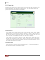
6.1.2 SNMP Setting
The SNMP gives users independence from the proprietary network management schemes
of some manufacturers. SNMP is supported by many WAN and LAN manufacturers
enabling true LAN/ WAN management integration.
To set the SNMP function:
1. Select “SNMP Setting” from Network menu.
2. Tick the “Enable SNMP Notification” option. Then setup the necessary options.
Option
Description
Description
Enter a description.
Contact
Enter the Contact information.
Name
Enter the Name information.
Location
Enter the Location information.
GetCommunity
Enter or change the GetCommunity value if needed.
SetCommunity
Enter of change the SetCommunity value if needed.
Trap ID 1
Enter the first Trap receiver IP address.
Trap ID 2
Enter the second Trap receiver IP address.
Trap ID 3
Enter the third Trap receiver IP address.
3. Click “Submit” to save the settings.
User Manual
57
NAS System
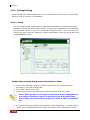
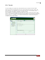
6.1.3 SMTP Setting
To set the Mail Notification function:
1. Select “SMTP Setting” from Network menu.
2. Tick the “Enable Mail Notification” option. Then setup the necessary options.
Option
Description
SMTP Server
Enter the SMTP Server IP address.
Use Secure
Authentication
To use secure authentication in SMTP server, enable this
option.
Account
Enter the account information.
Password
Enter the password for the account.
Sender
Enter the sender’s email address.
Receiver
Enter the receiver’s email address.
3. Click “Submit” to save the settings.
58
User Manual
NAS System
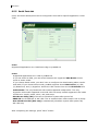
6.1.4 NTP Setting
NTP (Network Time Protocol) is an Internet standard protocol used to synchronize the
clocks of computers to some time reference.
By default, “Use Local Time Setting” is selected. This means the RAID subsystem will get
time information from local computer. Whenever the RAID subsystem is started or
restarted, you need to use “Sync RTC”. RTC Stands for Real Time Clock and is used to
set the time on the RAID controller. Setting the correct time plays an important role in
the system administration which helps administrators keep accurate record of when the
events actually occur.
To set the NTP function:
1. Select “NTP Setting” from Network menu.
2. Select the “Sync with a NTP Server” option. Then setup the necessary options.
Option
Description
Time Zone
Select the local time zone.
NTP Server
Enter the NTP Server IP Address.
3. Click “Submit” to save the settings.
User Manual
59
NAS System
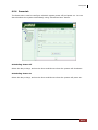
6.1.5 Sync RTC
When time setting is not configured to get time from an NTP server (“Use Local Time
Setting” option is selected in NTP Setting), the “Sync RTC” function must be used
whenever the RAID subsystem is started or restarted.
RTC Stands for Real Time Clock and is used to set the time on the RAID controller.
Setting the correct time plays an important role in the system administration which helps
administrators keep accurate record of when the event actually occurs.
To Sync RTC, select “Sync RTC” from Network menu and click “Submit".
60
User Manual
NAS System
6.2 System Management
6.2.1 System Setting
Some RAID subsystem System settings can be configured to the user’s preference to
match certain application.
The following can be set using “System Setting” function in System menu:
Alarm Beeper:
The Alarm Beeper function item is used to Disable or Enable the RAID subsystem
alarm tone generator. When Alarm Beeper option is checked, the alarm beeper is
enabled.
Cache Type:
The RAID subsystem supports Write Through and Write Back cache type. Write
Back allows temporary saving of data in the volatile cache memory and data are
acknowledged to have been received once it reaches the cache memory. Write
Through allows saving the data in the disk drives and data confirmation is
acknowledged once the data are written to the disk drives.
Cache Ratio:
Select 10% to 90% or adaptive.
User Manual
61
NAS System
Notification Level:
Events are classified to 5 levels (Critical, Error, Warning, Notice, Info).
Event
Log Level
Slot inserted
Notice
Slot removed
Notice
Temperature back to normal
Notice
Voltage back to normal
Notice
PSU back to normal
Notice
Fan back to normal
Notice
UPS not present
Notice
UPS standby
Notice
Array deleted
Notice
Array created
Notice
Array modified
Notice
Array initialization completed
Notice
Array rebuild completed
Notice
Array expansion completed
Notice
Array parity checking completed
Notice
Disk clone succeeded
Notice
Volume created
Notice
Volume deleted
Notice
Volume modified
Notice
Over temperature
Warning
Over voltage
Warning
Low voltage
Warning
PSU not present
Warning
Fan not present
Warning
Fail to setup network configuration
Warning
Array initialization failed
Warning
Array rebuild failed
Warning
Array expansion failed
Warning
Array parity checking failed
Warning
Disk clone failed
Warning
Mirror disk clone failed
Warning
System restart
Warning
Parity error detected
Warning
Power Supply Unit(PSU) Fail
Error
Fan fail
Error
UPS on battery
Error
Bad sector reallocation
Info
Baud Rate:
Set the baud rate: 19200, 38400, 57600 or 115200 (Default: 115200)
To save the change in each setting, click the “Submit" button.
62
User Manual
NAS System
6.2.2 Channel Manager
The Channel Manager can be used to configure the SCSI Host Channels A and B options
to the preferred settings. Select “Channel Manager” function in System menu.
For each Host Channel, the SCSI ID, Wide, Speed Setting, Current Speed, and Tag
Queue can be set.
Option
Description
SCSI ID
Select 0 to 15 or Multiple ID. The RAID subsystem is like a
large SCSI device. A SCSI ID should be assigned and
selected from the list of SCSI IDs. If Multiple ID is selected,
you can map ID to a host channel.
Wide
If enabled for a wide bus, the throughput is double transfer
rate, because each transfer is of 16 bits or two bytes. For
example, if Wide option is enabled, the Speed Setting can
have maximum transfer speed of 320MB/sec.
Speed Setting
Select the preferred Speed setting. The options are 80
MB/sec, 160 MB/sec, and 320 MB/sec for Wide mode. 40
MB/sec is available when Wide is disabled.
Current Speed
This shows the current speed for the host channel.
Tag Queue
When this option is enabled, it enhances the overall system
performance under multi-tasking operating systems by
reordering tasks or requests in the command queue of the
RAID system. This function should normally remain enabled.
User Manual
63
NAS System
After setting the preferred option, click “Update” to save the changes.
To see the current settings, click “Refresh”.
64
User Manual
NAS System
6.2.3 Modify Password
To set or change the login password of RAID subsystem, click “Modify Password” function
in System menu. Enter the old password in the Old Password field, and the new
password in the New Password and Confirm New Password fields.
Click “Submit” to save the change.
User Manual
65
NAS System
6.2.4 Upgrade Firmware
The RAID controller’s firmware can be upgraded when new firmware version is available.
Select “Upgrade Firmware” function in System menu then click “Upload”.
Select the firmware file. Click “Open” to start updating.
66
User Manual
NAS System
The firmware file will be uploaded to the RAID controller. Then the upgraded process will
be started.
After the upgrade is completed, the subsystem will automatically restart. User needs to
login again to proRAID Manager GUI after subsystem has restarted.
User Manual
67
NAS System
6.2.5 Restart
The RAID subsystem can be restarted using the “Restart” function in System menu. This
is normally done after firmware upgrade.
Click the “Submit” button to restart the RAID subsystem.
68
User Manual
NAS System
Chapter 7 Other proRAID Manager Menu Functions
7.1 Event Log
7.1.1 Event Log
The RAID subsystem’s event log information can be displayed by selecting “Event Log”
function in Event Log menu.
To update the current displayed event logs, click “Refresh”.
User Manual
69
NAS System
7.1.2 Export Log
The RAID subsystem’s event log information can be saved to local destination by
selecting “Export Log” function in Event Log menu.
Click “Submit” to save the event log. The file type of the exported event log will be in
XML.
70
User Manual
NAS System
7.2 Information
7.2.1 Disk Information
To view detailed information about the disk drives in the RAID subsystem, select “Disk
Info” function in Info menu. The Slot ID (Disk#), the disk vendor, model, capacity,
number of remapped bad sectors, firmware version, and state are shown.
When disks are already member of an Array, the State will show USED. It will show FREE
when not yet used.
Each member disk drive can be mark as faulty. Click the “Mark Faulty” button for the
disk drive.
NOTE: Setting disk as faulty can cause unrecoverable data damage
for some RAID levels. Use this function with caution.
User Manual
71
NAS System
7.2.2 RAID Information
To view information about existing Array and Volume in the RAID subsystem, select
“RAID” function in Info menu. Then select the Array name from the list of Arrays. The
Array Info and Logical Volume Details will be displayed.
The logical volume details can be shown in grid view using “Grid View” button. Default is
Chart View.
72
User Manual
NAS System
7.2.3 System Information
Use the “System Info” function in Info menu to view the RAID subsystem information.
The Vendor Name, Serial No., Product ID, CPU Name, CPU Speed, Memory Size, Memory
Speed, BBM Module installed or not, ECC DRAM support, Subsystem Model, Controller
Model, Firmware Version, Disk Channel Type, Number of Host Channels, Host Channel
Type, Host Channel Sync Speed, Number of Slots, Number of Backplane Slots, Baud
Rate, Cache Type, Cache Ratio, Beeper enabled or not, Log Level, proSES enabled or not,
and JBOD Model appear in this screen.
User Manual
73
NAS System
7.2.4 Hardware Monitor
To view RAID subsystem’s hardware information, select “Hardware Monitor” in Info
menu.
The Hardware Monitor information provides the power supply status, fan speed,
temperature, and voltage levels of the RAID subsystem. All items are also unchangeable.
The warning messages will indicate through the LCD, LED and alarm buzzer.
74
Item
Warning Condition
Fan Speed
< 2000 RPM
Power Supply +3.3V
< 2.97V or > 3.63V
Power Supply +5.0V
< 4.5V or > 5.5V
Power Supply +12V
< 10.8V or > 13.2V
System Temperature
> 70°C
HDD Temperature
> 55°C
User Manual
NAS System
7.3 Raid Task
7.3.1 Raid Status
To view the RAID status of an Array, select “Raid Status” in Raid Task menu. The List of
Arrays, and the RAID Level, Capacity, Member Disks and Status are displayed.
The states available are:
Status
Ready
Need to Rebuild
Initializing
Rebuilding
Expanding
Verifying
Cloning
Fail
If the RAID is rebuilding, initializing,
expanding, checking or cloning, the progress
of the task will be displayed, e.g. ‘Initializing
75%’.
User Manual
75
NAS System
A Parity Check function is available for existing Arrays with parity, such as those
configured with RAID level 3, 5, 6, 30, or 50, to check the consistency of parity blocks,
i.e. verify that parity information matches the stored data.
Click “Check Parity” button to start performing parity check. A message will be displayed.
The percentage of parity checking progress is displayed in Status field.
To cancel current Parity Check process, click the “Cancel Parity” button.
A message will be displayed.
76
User Manual
NAS System
7.4 S.M.A.R.T.
7.4.1 Disk Health
The RAID subsystem uses the SMART (Self-Monitoring, Analysis and Reporting
Technology) information available in the disk drive to monitor the disk health.
To view SMART information of a disk drive, select “Disk Health” in S.M.A.R.T. menu.
Then click the disk drive. The Disk ID and Disk Status of the selected disk are displayed.
The SMART attributes and its values and threshold values are also shown.
The Threshold Value is the boundary for the attribute Value before the disk
becomes unstable. The higher the attribute Value compared to the Threshold Value,
the better. If the attribute Value becomes smaller than the Threshold Value, the disk
is not in good state.
User Manual
77
NAS System
7.4.2 Diagnosis Disk
A diagnostic function is available to diagnose the disk health status.
Select “Diagnosis Disk” in S.M.A.R.T. menu. There are two types of diagnosis: Quick and
Extended.
After selecting the Diagnosis Type, click “Submit”. The disk diagnosis process will start.
NOTE: When Disk Diagnosis is running, it cannot be stopped. It
must be completed.
The “Extended” Diagnosis Type takes long time to complete, from
few hours to several hours depending on the size of the hard disk.
78
User Manual
NAS System
PART II proNAS System
User Manual
79
NAS System
Chapter 8 Introduction
The NAS system comes with “proNAS” NAS management solution and proBackup” client
backup solution as well as proNAS HA solution (optional) to provide the enterprises the
most flexible, scalable, securable and manageable NAS environment. Administrator can
centralize and easily manage the NAS nodes via Internet/Intranet and enhance greater
data availability via proNAS.
8.1 proNAS Key Components
NAS Device Manager: Provides configuration of physical hard disks with
Hardware RAID Controller.
NOTE: This NAS model does not support NAS Device Manager. Use
the proRAID Manager GUI to configure the RAID controller.
proNAS Manager: Provides several management tools to ease the NAS
administration job.
Volume Manager: Responsible for volume management. Configuration of
volume groups, logical volumes, volume snapshot and volume replication.
Account Manager: Local and external account configuration. Import large
accounts.
Backup Manager: Supports system configuration backup and setup the backup
plan for data backup.
Share Manager: Share configuration and ACL setting. This also includes
Rsync and Duplication functions.
System Manager: System configuration and firmware upgrade
Network Manager: Configuration of network information and trunking.
Log Manager: Contains NAS system logs.
Event Manager: Configuration of email notification and system actions when
events occur.
File Manager: Provides user logon mode for share owner to perform folder and
file management such as share folder access control.
proNAS HA: (optional). Provides function of High Availability (two-node cluster)
in Active-Standby mode.
proBackup: Provides web-based GUI backup solution for desktop clients.
Each function of these components is described in the following Chapters.
NOTE: Some pictures and screenshots might be different with the
actual machine.
80
User Manual
NAS System
8.2 Installation and Configuration Phases
The installation and configuration of a proNAS system can be divided into five phases.
Phase 1: Set up the Hardware RAID Controller and create Array and Volume.
Prior to proNAS system configuration, a basic hardware RAID
configuration must be setup. Please refer to Section 8.3 for the basic
setup instructions. For more information about creating Array and Volume,
refer to Chapter 5.
Phase 2: Configure proNAS and its components with proNAS Manager. This is
described in details in Chapter 9 proNAS Manager. To configure proNAS,
you need to:
Join a disk (storage device created in proRAID Manager) to the
system default volume group “proNASVG” using Volume Manager.
This is described in Chapter 9 Section 9.1.1 to 9.1.2.
Configure the network settings via Network Manager. This is described
in Chapter 9 Section 9.2.1.
Create or import accounts with Account Manager as described in
Chapter 9 Section 9.3.
Setup the shares using Share Manager and assign account/group
permissions. This is described in Chapter 9 Section 9.4.
Windows clients can start using the proNAS shares using CIFS
protocol. UNIX/Linux clients need to enable NFS protocol (disabled by
default).
Phase 3: Perform NAS system maintenance.
Maintain system via System Manager, as described in Chapter 9
Section 9.5
Check system status using Log Manager and Event Manager. This is
described in Chapter 9 Sections 9.7 and 9.8.
Backup system configuration and data using Backup Manager. This is
described in Chapter 9 Section 9.6.
Phase 4: (Optional) Setup proNAS HA for high-availability environment. Please
refer to Chapter 12 for proNAS HA configuration.
Phase 5: Users can store and backup data into proNAS system.
Store data into proNAS system using File Manager, as described in
Chapter 10.
Backup data into proNAS system using proBackup, as described in
Chapter 11.
User Manual
81
NAS System
8.3 Basic Setup Instructions in Creating Array and Volume
NOTE: If you have already created an Array and Volume, you may
skip this section.
1.
Configure your client computer to be able to connect to RAID controller’s R-Link
IP address (default is 172.16.0.2).
2.
Open web browser, enter the IP address, and login to proRAID Manager GUI.
Enter the subsystem name and the password (default is 00000000).
3.
To create Array and Volume using Quick Setup, select “Raid” menu then “Quick
Setup”.
82
User Manual
NAS System
4.
Enter Array Name, Volume Name, select the disk drives to be included in the
Array, and select RAID Level and Stripe Size (Block Size should remain as 512
Bytes). Click “Submit” when done.
5.
The Array and Volume will be created and initialized in background mode, and
the volume is ready for access by the NAS system while initializing in background
mode.
User Manual
83
NAS System
6.
When Quick Setup is used, the Volume will be mapped to both Host Channels A
and B as LUN 0. Since the Volume will not be used in Host Channel B (the
Volume only needs to be accessible in Host Channel A in the NAS system), the
Volume needs to be re-mapped and Host Channel B LUN 0 must be disabled. To
modify the LUN mapping, select “Raid” menu then “Modify Volume”. Select the
Array name and Volume name. Click Activate option of Host B to remove the
check mark, and then click Submit.
NOTE: Accessing the same Volume in both Host Channels A (NAS
system) and B (another host/server connected) will have data
access problem.
NOTE: The Volume (LUN 0) will appear to the NAS system as a
SCSI disk device (e.g. /dev/sda). Restarting the NAS is necessary
to detect the newly created Volume.
84
User Manual
NAS System
8.4 Setting proNAS IP Address and Connection to Management GUI
NOTE: Java 2 Runtime Environment (J2RE) 1.4.2 or later must be
installed before using the proNAS management interface. (Free
download from: http://java.sun.com/j2se/index.jsp)
1. If necessary, make changes in the network settings of your computer to connect
to eth0 IP address (see table below) and be able to open the NAS administration
page.
Entity
Eth0 IP address
Subnet Mask
Hostname
Username
Password
Default Value
172.16.0.1
255.255.0.0
proNAS
admin
proware
NAS Default Values
2. Open Web browser.
3. Enter the following URL in the address bar: http://172.16.0.1 then press Enter.
4. In the page that opens, click “Admin Login” command button to enter the NAS
administration page.
START button on the first proNAS
User Manual
85
NAS System
5. Enter Account as “admin” and password as “proware” and click the Logon
command button.
Login Screen
NOTE: proNAS supports language options: English, Chinese
(Taiwan), Chinese (China), Japanese, Korean, Polish (Poland), and
Russian (Russia). You can select your preferred language before
logon.
6. The proNAS main screen will be displayed showing proNAS, NAS Device Manager,
and Event Manager.
“Change Password” option
NOTE: For security reason, it is necessary to change the default
proNAS admin password. Click the “Change Password” button and
enter the new admin password.
86
User Manual
NAS System
Chapter 9 proNAS Manager
proNAS supports Multi-Node Management. If you have several NAS subsystems
connected to the intranet, you can see all these systems when you login to the proNAS
system. The IP Address section lists the NAS systems connected to the network. proNAS
Multi-Node Technology is based on UDP Multi-Casting technology. The proNAS managers
are listed below.
The proNAS managers are:
1. Volume Manager
2. Network Manager
3. Account Manager
4. Share Manager
5. System Manager
6. Backup Manager
7. Log Manager
8. Event Manager
User Manual
87
NAS System
9.1 Volume Manager
The Volume Manager is responsible for disk and volume management.
A Volume Group consists of one or more disks that could be individual physical disk(s) or
RAID disk(s), which is/are Volume(s) created using proRAID Manager. The default
proNAS Volume Group (proNASVG) must be created first by joining at least one “New” or
“Non_Initialized” disk to this volume group. The proNASVG holds the NAS system
configuration and the default system Logical Volumes, such as home, public, proBackup
Device, and proBackup Extended Device, as well as user-defined Logical Volumes. Files
and folders reside on these Logical Volumes.
The default proNASVG Volume Group cannot be deleted. When proNASVG is created, the
XFS file system is set in each default Logical Volume. XFS file system is also set in all
user-defined Logical Volumes. XFS is a high performance journaling file system and
provides better recovery time to repair a file system in case of FS damage. The proNAS
Volume Group will dynamically allocate some space from its assigned disks, and
allocation may fail if no more disk space is available. Therefore, make sure to regularly
monitor the available free space of proNAS Volume Group.
The
Volume Manager can perform the following function:
Create a VG (volume group)
Join New Disks
Reset a VG (volume group)
Remove a VG (volume group)
Create Logical Volume
Create Snapshot
Create Replication
88
User Manual
NAS System
9.1.1 Volume Group Management
Volume Group (VG) is created by joining at least one disk, which can be physical disk or
RAID disk(s). Logical Volumes are created under the Volume Group.
proNASVG is the system default VG. It must be created first in order to use the NAS
system. To create the proNASVG, it is necessary to join at least one “New” or
“Non_Initialized” disk into proNASVG. The default proNASVG cannot be deleted or reset.
Admin can create other VG by joining other new or “Non_Initialized” disk, create or
remove LV in this VG, join any new disk, remove any disk and reset the VG.
NOTE: If the Disk List in Volume Manager does not show any RAID
disk (for example: /dev/sda) but and Array and Volume has
already been created, it is necessary to restart the proNAS system.
Go to System Manager, select Reboot tab, and click Reboot Now
button. Then re-login to NAS administration page.
9.1.1.1 Create the proNASVG Volume Group
To create the proNASVG, perform the following steps:
1. In the proFamily tree, select Volume Manager. Verify that the Disk List shows at
least one disk and the Status is “Non_Initialized’. Noticed in the Volume Group
List that the proNASVG has no Disk List.
NOTE: The system default Volume Group “proNASVG” cannot be
deleted or reset.
User Manual
89
NAS System
2. Select proNASVG under Volume Manager and click “Join New Disk” button.
3. Select the Disk(s), e.g. /dev/sda, /dev/sdb, etc., that will be joined to proNASVG
from the list of Available Disk(s). The default Unit Size of proNASVG is 512MB. If
needed, the Unit Size can also be changed. Click “OK” when done.
NOTE: Unit Size is the Physical Extent or block size used in the
Volume Group.
4. A confirmation message will appear. Select “Yes” to proceed.
90
User Manual
NAS System
5. Another confirmation message will appear. Select “”Yes” to proceed.
6. The process of joining disk to the VG will start.
7. When the process of joining disk to VG is completed, the NAS will reboot to free
some used system memory. A warning message will be displayed. Click “OK” to
close the message.
8. Re-login to proNAS management GUI. The Volume Manager will show the joined
disk as “IN_USED” and the Volume List will show the system default Logical
Volumes “home” and “public”.
NOTE: The other system default LVs proBackup Device and
proBackup Extended Device will only be created and become
visible in the Volume List when the proBackup Service is started.
User Manual
91
NAS System
9.1.1.2 Create another Volume Group
To create another VG, verify from Volume Manager Disk List if there is available free or
“Non_Initialized” disk. If there is none, a new Volume (RAID disk) must be created first
using proRAID Manager. If a new Volume has already been created, the NAS system
must be restarted in order to detect the new RAID disk. To restart the NAS, select
System Manager under proNAS, then click Reboot tab then click “Reboot Now” button.
Re-login to NAS administration page after reboot.
To create another VG, perform the following steps:
1. In Volume Manager, click “Create VG” button.
2. Enter the Volume Group Name. Click “Save” when done.
92
User Manual
NAS System
3. A confirmation message will appear. Select “Yes” to proceed.
4. Click “Join New Disk” to continue with creating the new Volume Group.
5. Check the disk(s) to be joined to the VG. Click “OK” when done.
User Manual
93
NAS System
6. A confirmation message will appear. Select “Yes” to proceed.
7. A process window will appear.
8. When the process of joining disk to the new VG is completed, the newly created
VG will be shown.
NOTE: The new VG has no default Logical Volumes. Admin can
create new Logical Volumes.
NOTE: The NAS supports up to 5 Volume Groups. Volume Group is
the highest level abstraction used within the NAS system. It
gathers together a collection of Physical Volumes (consisting of at
least one disk device, such as /dev/sda) and Logical Volumes into
one administrative unit.
94
User Manual
NAS System
9.1.1.3 Reset and Remove Volume Group
If you choose to reset the Volume Group, all the data will be erased. Use the “Reset
Volume Group” function only when necessary, and when the data from the VG have been
backed up or you do not want to keep the data.
1. Select “Reset Volume Group” button.
2. Select “Yes” to confirm.
3. Click “Remove”.
User Manual
95
NAS System
4. Select “Yes” from the confirmation message.
5. Verify from Volume Group List in Volume Manager that the VG has been removed.
NOTE: The system default Volume Group “proNASVG” cannot be
deleted or reset. Only custom created VG can be reset.
96
User Manual
NAS System
9.1.2 Logical Volume Configuration
9.1.2.1 Create new Logical Volume
To create a new Logical Volume, follow these steps:
1. Double-click on a VG name. Click “Create New Volume” button.
2. The LV Configuration tab will be displayed. Enter the Logical Volume name and
the volume size (in MB). You can also enable the “Send email when not enough
space” option to send an email notification to email recipients specified in Event
Manager if the remaining free volume size is smaller than the size entered in this
option. Click “Save” when done.
User Manual
97
NAS System
3. Select “Yes” from the confirmation message to create the LV.
4. A process window will be shown.
5. The new Logical Volume will be shown.
98
User Manual
NAS System
9.1.2.2 Extending Logical Volume Size
When the Logical Volume free space gets smaller and smaller, the Logical Volume size
can be extended to allow more space for storing data. To extend the LV size, follow
these steps:
1. Select the LV that will be extended then click “Extend LV Size” button.
2. Enter in the “Extend size” box the additional size to be used for extension. Verify
from the Free Volume Group Size (MB) the allowable size to be used in extension.
3. The Logical Volume will be extended.
User Manual
99
NAS System
4. Verify the new LV size.
100
User Manual
NAS System
9.1.3 Volume Snapshot
Snapshots are point-in-time copies of a logical volume. This allows the system
administrator to create a new block device which presents an exact copy of a logical
volume, frozen at some point in time. As changes are made to the original volume, the
snapshot remains the same and looks exactly like the original at the time the snapshot
was created.
A Snapshot can be created manually or scheduled. Admin need to enable first this
special function.
NOTE: Logical Volume with snapshot cannot be extended nor
replicated (see next section about Volume Replication).
To enable Snapshot function, select Volume Manager then click Options tab. Tick the
“Enable Snapshot function” option.
NOTE: Creating Snapshots while a Logical Volume is under heavy
I/O will slowdown the I/O access or interrupt the I/O process to a
Logical Volume.
User Manual
101
NAS System
9.1.3.1 Create Snapshots Manually
To manually create snapshots:
1. Select the Logical Volume, go to Snapshot tab and click “Create Snapshot”.
2. A confirmation message will appear. Select “Yes”.
3. The Snapshot configuration window will be displayed. A system-created Snapshot
name is automatically created. The default snapshot name can be renamed if
needed. Enter the new Snapshot Size (in MB) if the size shown need to be
changed. See details about Snapshot Options below. Click “Create Snapshots” to
start creating snapshot.
102
User Manual
NAS System
Snapshot Options:
Snapshot Name: The default snapshot name is created by appending the date
and time to the volume name. You can modify the snapshot name but the prefix
volume name will still remain.
Size (MB): This indicates the size of the snapshot volume that will be created.
The default is 10% of the size of the logical volume where snapshot is to be taken.
The size of the snapshot volume will be multiple of the PE size.
Origin LV Size: This indicates the size of the Logical Volume where the new
snapshot volume will be created.
Free Volume Group Size (MB): This indicates the amount of free space on the
volume group where the new snapshot volume will be created.
Mount: When checked, the created snapshot volume will be automatically
mounted. When a snapshot volume is mounted, the existing share from the
snapshot volume will be accessible. Note that a snapshot volume is a read-only
volume.
ID: This specifies the shares created under this logical volume.
Snapshot share name: This specifies the name of the snapshot shares. Your
may access these shares by mounting the snapshot volume. The naming format
used is: the last two digit of the year, followed by the month/date, and then
followed by the hour/min/sec. For example: "060123_171516".
4. A process window will be displayed.
5. When snapshot has been created, it will be shown in the Snapshot List of the
Logical Volume.
User Manual
103
NAS System
9.1.3.2 Create Snapshots Based from Schedule
To create scheduled snapshots:
1. Select the Logical Volume, go to Snapshot tab and click “Edit”.
2. Edit the following snapshot options listed below then click “Save” when done.
104
User Manual
NAS System
Snapshot Options:
Snapshot Numbers: Specifies the total number of snapshots that will be created.
Snap Ratio (%): This is the ratio in percentage between the snapshot volume
and the volume of origin. This indicates the ratio of the volume size that will be
set as the size of the snapshot volume. For example, if your logical volume is 1GB
and the Snap Ratio is 10%, the size of the snapshot volume that will be created is
128MB, assuming that your PE size is 128MB and below. The snapshot volume
size will always be a multiple of PE size and the smallest snapshot size is equal to
the PE size.
Overwrite: Selecting this option will automatically delete the oldest snapshot if
the total number of snapshots is already exceeded.
Mount: When checked, it means that the created scheduled snapshot will be
automatically mounted.
Reserved/VG Free Size (MB): The left side indicates the total volume space
that will be used for the creation the snapshots. The right side indicates the free
space of the volume group available for use.
Execute Day: Specifies whether the scheduled task is to run on the selected
day(s).
Execute time:
Once - Specifies the time of the day when the scheduled task will be taken.
Every - Specifies how often the scheduled task is to be repeated. You can
also select the starting time and the ending time.
Snapshot Lists:
Mount - Allows you to mount the snapshot volume. All snapshot volumes will
be mounted read-only. By mounting the snapshot volume, the files under this
snapshot volume will become accessible.
Name - This specifies the name of the snapshot volume. If the snapshots are
created by schedule, proNAS will automatically create the snapshot name. The
format that will be used is: the last two digit of the year, followed by the
month/date, and then followed by the hour/min/sec. For example:
"060123_171516".
Date - This indicates the date and time when the snapshot was created.
Used Size - This indicates the space used by the snapshot data. The right
side is the size of the snapshot volume. If the used space nearly exceeds the
snapshot volume capacity, it will be set as "Invalid" and will be un-mounted
automatically to keep the system consistent.
3. A confirm message window will be displayed. Select “Yes” to proceed.
User Manual
105
NAS System
4. An “Updating Volume Setting” message will be shown.
5. When the snapshot setting of LV has been set, click “Enable Scheduled” to active
scheduled snapshot.
6. A clock-like icon will appear on the left side of the LV which means a scheduled
snapshot is active. To disable the schedule, click “Disable Scheduled”.
106
User Manual
NAS System
7. After disabling the schedule, the “Enable Scheduled” button will become available.
9.1.3.3 Delete Snapshots
1. Select the Logical Volume where snapshot will be deleted, then go to Snapshot
tab. Click the snapshot that will be deleted then click “Delete Snapshot”.
2. Select “Yes” to delete the snapshot.
User Manual
107
NAS System
3. A process window will be shown.
4. The deleted snapshot will no longer exist in the Snapshot List.
108
User Manual
NAS System
9.1.4 Volume Replication
Replication function enables proNAS to replicate a logical volume from one NAS server
(source) to another NAS server (destination). Replication involves intelligent copying and
maintaining of exact copy of a volume from a source server to a destination server. The
destination volume is always an exact copy of the source volume. This is done by
mirroring the whole block device via a standard network interface. This solution creates
a real time replication of data. However, it does not create a cluster solution where you
can have a highly available system.
Note: Logical Volume under snapshot cannot be replicated.
NOTE: Starting with proNAS version 1.1.14, replication of Logical
Volumes with LV capacity up to 3,800,064 MB is now supported.
To enable Replication, select Volume Manager then click Options tab and tick “Enable
Replication function”.
User Manual
109
NAS System
9.1.4.1 Replication Configuration
To setup Replication between two NAS servers:
1. Admin need to login to the administration page of the two NAS servers.
2. On the primary NAS (source), select the Logical Volume which will be replicated,
then click “Create Replication”.
NOTE: The logical volume to be replicated from source proNAS
must not exist in the destination proNAS. If the destination
proNAS has the same logical volume, replication cannot be setup.
110
User Manual
NAS System
3. The Create Replication window will be displayed. Set the options below and click
“OK” when done.
Replication Options:
[Remote]
Local - Select the IP address of the local (source) proNAS that will be used for
replication.
Remote - Select or type manually the IP address of remote (destination) proNAS
that will be used for replication.
NOTE: The local and remote IP addresses serve as the channel
between the source and destination NAS servers. This is where the
replication of data takes place. Please be sure to have a good
connection on this medium. As much as possible, set this channel
as a dedicated or a private network. It is recommended to use
different Ethernet port for replication from the Ethernet port used
for data access. It is best to use a crossover network link between
the Ethernet ports involved. Refer to Network Manager Section for
configuring Ethernet port.
Remote VG - Select the VG on remote proNAS where the replicated logical volume
will be created.
User Manual
111
NAS System
[Setting]
Port to Bind - A TCP port to bind locally and is used to connect to the remote node.
Default is 7788.
NOTE: User cannot use ports that already have been used.
Available ports are from 7788 to 77xx.
Connection Type: proNAS supports two types of data replication protocols:
Sync - Synchronous. The system will acknowledge the transaction as completed
after the data is written to the disk of destination proNAS. It is recommended to
use this mode. In most cases, this connection type preserves transaction
semantics. Write IO is reported as completed if it has reached the remote disk.
Async (for high latency network) - Asynchronous. The system will acknowledge
the transaction as completed after the data is written to buffer. It provides faster
transmission and is suitable for busy network. Write IO is reported as completed
if it has reached the local TCP send buffer.
Max Sync Rate – This sets the limit of the bandwidth that will be used by the
synchronization process. Default is 30MB/sec. Minimum value is 4MB/sec and
maximum value is 680 MB/sec – for high latency network environment (e.g. bonding
on Gigabit Ethernet).
Send buffer size (K) - It is the size of the TCP socket send buffer. You can specify
smaller or larger values. Larger values are appropriate for reasonable write
throughput with asynchronous protocol over high latency networks. Default is 512K
and maximum is 1024K.
Time out (sec) - It is the value to wait for connection timeout if the remote node is
degraded. If the remote node fails to send the response packet within the specified
timeout time, the remote node will be considered dead and the TCP/IP connection is
abandoned. The default is 6 sec. Minimum is 1 sec and maximum is 60 sec.
When Lost Connection: When the replication connection is lost, the replication
program can either go stand-alone or will try to reconnect.
Reconnect: The replication program will attempt to reconnect. (Default)
Stand-alone: The replication program will not attempt to reconnect and will go
on stand-alone state. All IO request are only passed locally and no replication.
NOTE: Before replication will be successfully created, a 4GB logical
volume will be created on each node. This will serve as the
metadata device for the replicated volume. This volume is not
mounted and will not be seen on the proNAS GUI. Please be sure
to have an extra 4GB space on either side of your NAS nodes.
112
User Manual
NAS System
4. A message box will be displayed.
5. Initialize the Replication by clicking “Initial Replication” button.
NOTE: After creating a replication, a similar logical volume will be
created on the destination server under the specified VG. At this
point, the replication is not yet initialized and no synchronization.
Replication still needs to be initialized. After selecting “Initial
Replication”, the first node will then connect to the second node
and starts to synchronize. Synchronization typically takes quite a
while especially on larger logical volumes. After initializing, the
source node should be in "Primary" state and the destination node
should be in "Secondary" state. If this is the state, you have now a
working replication. Initializing should be done in the source
volume.
6. The volume replication setting will be initialized.
User Manual
113
NAS System
7. The volume replication synchronization process will start.
8. After the initial synchronization process is completed, the Status will show
“Primary/Secondary Consistent”.
114
User Manual
NAS System
9.1.4.2 Checking the status of your replication
Primary: The source volume. All the writing and reading are done on the primary
node.
Secondary: The destination volume. The replicated data on the secondary node is
used for backup only and is not accessible. Only the source data is accessible during
replication.
Unknown: The peer node fails to establish connection.
Setting the replicated volume on destination proNAS to be primary
To set the replicated volume to primary, first you need to set both nodes to
secondary. This can be done by setting the primary to be secondary. After both
nodes becomes secondary/secondary, go to the management GUI of the destination
node. Under the replicated logical volume, press the "Set Primary" button.
WARNING! The replicated volume on the secondary node must not
be mounted. Please do not attempt to mount it manually.
Setting the primary volume to be secondary
To set the primary volume to be secondary, just press the "Set Secondary"
button on the primary node.
Forcing the synchronization
To manually force the synchronization, press the "Force Sync." button. The data
on the primary node will be forcefully synchronized to the secondary node.
Reconnect when the connection of the peer is lost.
To reconnect the replicated volume, press the "Reconnect" button. At some point
if the replication fails to establish connection to the other node, you may try to
set up a connection thru this button. This button will be enabled only if one of the
node losses connection.
Aborting the replication
To abort or drop the replication, press the "Abort Replication" button. To access
the data on the replicated volume after aborting the replication, you may need to
create a share under destination volume whose share name must be equal to the
share name on the source proNAS.
User Manual
115
NAS System
9.1.4.3 Extending logical volume under replication
NOTE: Extending the size of a Logical Volume under replication is
not allowed. However, there is a work around to extend the LV size.
The following are the steps:
7. Abort the replication by selecting “Abort Replication”.
8. Remove or delete the replicated logical volume on the destination proNAS.
9. Extend the capacity of the source logical volume. Please note that there should
be enough space on the logical volume of the destination proNAS to
accommodate the extended logical volume space.
10. Create a new replication using the extended source logical volume.
116
User Manual
NAS System
9.1.5 iSCSI
The iSCSI function in proNAS makes a logical volume become an iSCSI target LUN.
Note: You can’t enable iSCSI function in a Logical Volume if
Snapshot or Replication exists.
To enable iSCSI
function, select Volume
Manager then click
Options tab and tick
“Enable iSCSI”.
9.1.5.1 iSCSI Configuration
To configure iSCSI:
4. Select the logical
volume and click
the iSCSI tab.
NOTE: If you have
not created yet a
logical volume, you
must create first
before you can
select “Enable
iSCSI” in iSCSI tab.
User Manual
117
NAS System
5. Click “Edit” and tick
the “Enable iSCSI”
option.
6. Enter the target
name. If you want
to enable CHAP
authentication,
check the “Enable
Auth (CHAP)” option
and enter the
account and
password.
NOTE: iSCSI Target
name can only use
a~z, A~Z, and 0~9
characters
7. Click “Save” when
done.
118
User Manual
NAS System
8. A message box will be
displayed. Select “Yes”
to continue.
9. A progress box will be displayed.
10. The iSCSI volume
is ready. Note that
there is an “i” icon
on the left of
logical volume
name to denote
that this is an
iSCSI volume.
11. You may now connect to the iSCSI target LUN using iSCSI initiator.
User Manual
119
NAS System
9.1.5.2 Disable iSCSI in Logical Volume
To disable iSCSI:
1. Select the logical volume and click the iSCSI tab.
2. Click “Edit” and
remove the check
mark in “Enable
iSCSI” option.
Click “Save” when
done.
3. A confirm message box will be
displayed. Select “Yes” to proceed.
4. The iSCSI
function in the
logical volume is
disabled.
120
User Manual
NAS System
9.1.5.3 Restore iSCSI to Ordinary Logical Volume
The iSCSI volume can be restored back to normal logical volume and remove the iSCSI
function. The existing data in the logical volume will be deleted; so if there are important
data in the logical volume, a backup must be made.
To restore iSCSI to normal volume:
1. Select the logical volume and click the iSCSI tab. Select the “Restore to Volume”
button.
2. When a warning message is displayed, select “Yes” to proceed.
3. When a confirm message is displayed, select “Yes”.
User Manual
121
NAS System
4. A process window will show that the volume is being restored back to normal
logical volume.
5. The logical volume is restored to normal volume. Note that the “i” icon on the left
of logical volume name has been removed.
122
User Manual
NAS System
9.1.5.4 Extending iSCSI Logical Volume Size
The capacity of iSCSI volume can be extended to allow more data to be stored.
To extend iSCSI volume capacity:
1. Select the iSCSI volume. Click “Extend LV Size”.
2. Enter the additional capacity for the volume in the Extend size box. Note that you
cannot exceed the free/available size from the volume group. Click “OK”.
3. A Confirm message box will be displayed. The iSCSI target will be restarted
during volume capacity extension and iSCSI initiator(s) need to relogon/reconnect. Select “Yes” to continue.
User Manual
123
NAS System
4. The iSCSI logical volume capacity is extended.
124
User Manual
NAS System
9.2 Network Manager
Using the Network Manager, you can configure the NAS network settings. There are
three tabs in Network Manager: Network, Internet Gateway, and SNMP.
9.2.1 Network Setting and Trunking
There are two sections in the Network tab, the General Setting section and the Network
Adapter section.
The Network tab
Press “Edit” button to configure the Network settings and click “Save” button to update
new settings.
General Setting:
Host Name - The NetBIOS name of proNAS, it should be unique.
Domain/Workgroup - Windows domain name or workgroup. Domain name is
limited only up to 15 characters. For example: mydomain
DNS Suffix - The DNS suffix appended to server name to complete the server’s
FQDN. This includes the domain name, for example: mydomain.local
DNS Server - DNS server is responsible for mapping the machine name and IP
Address.
WINS Server - WINS Server is responsible for the setting NetBIOS name
resolution.
Edit DNS Table: If you have not set the DNS, you can use this button to edit DNS in
the DNS table. This is optional.
Edit Lmhost Table: You can use this option to define the resolution of NetBIOS in
the Lmhosts table. This is optional.
User Manual
125
NAS System
Network Adapter:
The Network Adapter section consists of the Adapter List and the Configuration section.
The Adapter List is the list of available Ethernet ports in the system. The number of ports
might be two or three depending on different models.
Adapter List: Lists the available Ethernet adapters.
Configuration:
Use Dynamic IP Configuration (BOOTP/DHCP) - If checked, this specifies
that this network connection will dynamically obtain an IP address from a
Dynamic Host Configuration Protocol (DHCP) server or from a Bootstrap Protocol
(BOOTP) server.
Enable this adapter on boot – If enabled, this adapter will be active when
proNAS starts up.
Enable default gateway on this adapter - If checked, the default gateway will
be enabled in this adapter. A default gateway is a local IP router that is used to
forward packets to destination beyond the local network. Only one default
gateway can be enabled in a certain time.
Device - Displays the type of Network Interface Card.
IP address – Shows the current IP address. To edit IP address, enter the new IP
address.
Gateway – Shows the current gateway IP address. To edit, type in a new
gateway IP address.
Subnet mask – Shows the current subnet mask setting. To edit, type in the new
subnet mask number.
MTU – The MTU size (Maximum Transmission Unit) in bytes. To modify the MTU
size for this interface, enter the new MTU size.
Network Trunking
ProNAS provides the network trunking/bonding function. Ethernet bonding refers to
aggregating multiple Ethernet channels together to form a single channel.
NOTE: It is necessary that the network switch supports the type of
trunking mode that will be used. Otherwise, the network
connections may be unstable.
126
User Manual
NAS System
To create a trunk adapter:
1. Click on the "Edit" button. Press the “Ctrl” key then at the same time select the
adapters that will be included in the network trunking then click on "Trunk
Adapter" button.
2. A warning message will be displayed. Click “OK” to proceed.
3. Setup the network settings. Select the Team Mode to use. Click “Create” when
done.
User Manual
127
NAS System
The Team Mode defines the type of operation for the bonded ports.
Team Mode options:
Fault Tolerant (Active_ Backup) - Active_Backup policy: If the active
Ethernet port fails, the standby Ethernet port will become active. This
enhances the availability of access to the NAS.
Load balance and Fault Tolerant (XOR) - XOR policy: Transmit based on
source MAC address XOR with destination MAC address. This selects the same
slave for each destination MAC address. This mode provides load balance and
fault tolerance.
Link Aggregation (802.3ad) - 802.3ad policy: Combines multiple physical
network links into a single logical link for increased performance. Transmits
and receives on all slaves in the active aggregator. Pre-requisite: the network
switch must support IEEE 802.3ad.
Load Balance (ALB) - ALB (Adaptive load balancing) policy: The receive load
balancing is achieved by ARP negotiation and does not require special switch
support.
4. Connect to proNAS using the new IP address used in network trunking.
128
User Manual
NAS System
9.2.2 Internet Gateway
proNAS provides Internet gateway function which enables proNAS to act as an Internet
Gateway, integrating DHCP service, routing and NAT. Using Internet gateway function,
administrators can easily enable and disable the Internet access for network users.
To configure Internet Gateway, press “Edit” button.
Configuration options:
DHCP's IP range starting from - means the lower bound (starting) range of
private IP addresses for DHCP
DHCP's IP range ending with - means the upper bound (ending) range of
private IP addresses for DHCP
Private Net Adapter - means the port connected to private network. This port
has to be a Static port and could also be a Trunk port.
WAN Adapter: means the port connected to WAN or Internet. This port could be
a Trunk port.
NOTE: When using Internet Gateway function, make sure the
Internet Gateway service is enabled in the Service tab of System
Manager.
User Manual
129
NAS System
9.2.3 SNMP/MRTG
The SNMP/MRTG service can be enabled to monitor proNAS network traffic. Select
Service tab of System Manager then enable SNMP/MRTG service. Click “Start” to enable
the service.
To view the SNMP/MRTG network traffic information, select the SNMP tab in Network
Manager.
For more information about MRTG service, please visit http://www.mrtg.org.
130
User Manual
NAS System
9.2.4 Network Test
This function allows to test whether a particular host is reachable or to check
connectivity to a particular IP address.
To test, enter the IP address in the IP address box then click “Network Test” button.
The result will be displayed in the area below the IP address box.
User Manual
131
NAS System
9.3 Account Manager
With Account Manager, the administrator can manage and administer local accounts as
well as import external domain accounts. proNAS will utilize external directory services
to do account authentications which currently supports ADS/PDC and NIS.
The main functions of the Account Manager are:
Authentication
User Account
Group Management
9.3.1 External Accounts Integration (Joining Windows or NIS Domain)
You can utilize external directory services to authenticate accounts. Currently, PDC/ADS
and NIS authentication are supported. You may choose any one of them or both at the
same time depending on your network environment.
9.3.1.1 Windows Authentication
If you would like to integrate proNAS with Windows environment, please select “Edit”
button then check "Enable Domain authentication". Set the necessary Windows options
then click “Save” to update settings.
NOTE: Hostname, Domain name and DNS Suffix need to be set first
in Network Manager.
132
User Manual
NAS System
Windows options:
Automatic detect Domain IP – This is enabled by default. When enabled,
proNAS will try to automatically detect the domain server’s IP address.
Hostname - Indicates the NetBIOS name of proNAS; must be set in Network
Manager.
Domain/Workgroup - Windows Domain name; must be specified in Network
Manager.
DNS Suffix - The DNS suffix used; must be set in Network Manager.
Domain Server IP - The IP address of the domain server. proNAS will
automatically acquire the domain server's IP address after setting the Domain
name in Network Manager if “Automatic detect Domain IP” option is enabled.
When “Automatic detect Domain IP” option is disabled, you need to manually
enter the domain server’s IP address.
Logon account (Administrator) – the administrator’s logon name in the
Domain Controller
Password - the administrator's password in the Domain Controller.
PDC/ADS Mode – The type of Domain Controller. Choose PDC for Windows NT
Server or ADS for Windows 2000/2003/2008 Server.
Auto Detect Enctypes – This option automatically detects the encryption type
used in Windows authentication. To manually select the encryption type, disable
this option and select the preferred encryption type from the EncType drop-down
list.
Enable NTLMv2 authentication - This parameter determines whether or not
smbclient will attempt to authenticate itself using the NTLMv2 encrypted
password. If enable, proNAS will only sent NTLMv2 and LMv2 responses. NTLMv2
authentication protocol is available only on WindowsNT4 with SP4 and Windows
2000 or later. Default is disabled.
Enable client schannel - This controls whether the client offers or even
demands the use of the netlogon schannel. Default is auto, means it offers the
schannel but does not enforce it.
9.3.1.2 Sample Steps to Join the NAS to Windows AD Domain:
1. Select Network Manager. In Network Manager –> Network tab, click “Edit” to
configure network settings.
2. Change the default proNAS Host Name if there are other proNAS systems in the
network. Enter the Windows Domain name in “Domain/Workgroup”. For example:
MYDOMAIN
User Manual
133
NAS System
3. Enter the DNS Suffix. The DNS suffix is the name appended to the server name to
complete the server’s FQDN. This includes the domain name. For example:
MYDOMAIN.LOCAL
4. Enter the DNS
Server and WINS
Server (IP address)
as necessary.
5. Click “Save” to
update changes.
6. Select Account Manager. In Account Manager –> Windows Authentication, click
“Edit”.
7. Tick “Enable Domain Authentication” option.
8. If the Domain Server IP is not detected (not shown), you can manually specify
the Domain Server IP by removing the check mark in “Automatic Detect Domain
IP” and entering the Domain Server IP address.
9. Enter the Domain Administrator Account and Password.
NOTE: No need to
include “domainname\” in
Domain
Administrator
Account.
10. Select the Domain
Server mode (PDC
or ADS).
11. If needed, change
the encryption type
to the same type
used by your
domain server.
12. Click “Save”. The
NAS will be joined
to Windows Domain in a while.
13. To verify, select Account under Account Manager; the domain user accounts
should be shown. You can also verify group accounts in Group List.
134
User Manual
NAS System
9.3.1.3 NIS Authentication
If you would like to integrate proNAS with UNIX/Linux environment, please select “NIS
Authentication” tab and click “Edit” button then check "Enable NIS authentication". Set
the necessary configuration options then click “Save” to update settings.
Configuration Options:
NIS Domain - Enter the NIS domain name
NIS server - Enter the IP Address of NIS server.
9.3.1.4 Sample Steps to Join NIS Domain:
1. Under Account Manager, select NIS Authentication tab. Click Edit.
2. Check the Enable NIS Authentication option. Enter the NIS Domain name (e.g.:
TESTDOM.LOCAL) and NIS Server IP address or FQDN. Click Save when done.
3. Click Account under Account Manager to verify that the NIS Accounts are listed in
the Account List, or select Group to display the NIS Groups in the Group List.
User Manual
135
NAS System
9.3.2 Local Account and Group Management
Account Management
The Account List in Account Manager includes Local users and External users, ADS/PDC
or NIS.
In Account menu, admin can perform the following functions:
Create a new Local Account
Enable and Disable an Account
Modify and Delete an Account
Mass Import Accounts
Refresh the Account List
Creating a new Local account
Following are the steps to create a new Local account:
1. Select Account Manager in the proFamily tree. Choose Account node under the
Account Manager. It will display all accounts under the Account List tab.
136
User Manual
NAS System
2. Press the "Create" button. System will display "Account List tab". Account List
tab consist of two tabs, "Properties" and "Permission". In the Properties tab, enter
the necessary information.
General:
Login Name - Input the login name, it should be unique in proNAS
Full Name - the complete name of the account
Directory Service - system will display if the directory service is Local or
ADS/PDC,NIS
Create Date - system will display the create date of the account.
UID - In UNIX or Linux, OS will assign a unique user number called UID to access
the system resource. (UID range is 1 to 65535). proNAS may either assign a new
UID automatically starting from 500 or you can manually specify the UID. Domain
accounts will have a UID starting from 10000-30000.
Quota Size (MB) - This specifies the quota (usable space) of a user for its home
folder. The default is 10MB.
Set it to default value for new account – When this option is enabled and the
Quota Size value has been changed from 10MB to another value, the new value
set in Quota Size will become the new default Quota Size when other accounts
are created.
Set Password – Click this button to set the account's password. Passwords have
to be at least 6 characters.
User Manual
137
NAS System
Status:
Current status: Displays Enable or Disable.
Used Size (MB): Displays the current used size.
Use the following guidelines to ensure that you are using a valid Account name:
Account names must start with a small alphabet letter.
Account names cannot be longer than 32 characters.
Account names should be unique. No account names must be the same. No
account names must be the same with share names.
Account names cannot contain blank spaces.
Account names cannot begin with a dash (-) and cannot consist of only a single
dash.
Account names cannot contain the following characters: /\[]";:|<>+=,?*
Account names cannot be duplicated with the system default accounts, i.e. root,
mail, news, operator, gopher, nobody, ftp, games, rpc, adm, nobody, etc.
3. After completing the settings, press the "Save" button to save settings, or you
may go to "Permission" tab to have a look at the permissions of the account then
click “Save” button when done.
138
User Manual
NAS System
Permission tab
Joined Groups: The account has gained access right because of joining certain
groups.
Individually Authorized Shares: Implies that the account has gained access
rights individually.
Ownership: Implies that the account has gained access right because it is the
owner.
NOTE: Newly created accounts will automatically be a member of
"users" group.
Enabling and Disabling an Account
Account Manager allows the administrator to enable or disable a user account. When an
account is disabled, the account cannot be used to login and access proNAS.
To forbid certain user account in accessing proNAS, highlight the account then press
"Disable" button. The account will be shown with “Status” as Disable. If you would like to
re-enable the user account proNAS, press "Enable" button. Disabling account "admin" is
not allowed as well as all ADS/PDC and NIS accounts.
User Manual
139
NAS System
Deleting an Account
If you would like to delete a certain account, highlight the account then press "Delete"
button. The user's home directory will be deleted. If the user owns one of the share, the
owner of that share will be set to "admin". Account "admin" is not allowed to be deleted
as well as ADS/PDC and NIS accounts.
Modifying an Account
If you want to modify an account, double-click on the account. You can only
modify the password and permissions. If the account is an external domain account
(created by ADS/PDC or NIS domain server), the account and password can not be
modified in proNAS Account Manager. In such a case, you can only modify the
permissions.
Importing of Accounts
proNAS provides Import Account function for creating large number of accounts instead
of adding an account one by one. Administrator can create multiple user accounts in a
text file with the following format: UID, Logon Account, Logon Password, Full Name.
Example:
1019, david, proware, David Huang
1020, rocky, proware, Rocky Lee
To import the accounts, click on "Import Accounts" button then select the text file.
NOTE: The information for each account must start on a new line.
If account creation fails for any account, proNAS skips that line (of
account information) and continues with the next line.
NOTE: Account text file with UTF8 format is supported in proNAS
1.1.14 and later versions.
Refreshing the Account List
Use the “Refresh” button to automatically synchronize any new accounts created in
ADS/PDC or NIS domain.
140
User Manual
NAS System
Group Management
Using group management, admin can organize access to proNAS shares. For example, a
Sales group can be created for the sales department and this group can be assigned
read-write access to the Sales Report share. All account members of the Sales group can
have access to the Sales Report share.
Group List tab
The Group List tab shows the Local and External (ADS/PDC or NIS) Groups.
Group management allows the administrator to:
Create or Delete a Local group
Modify a Group
Refresh the Group List
proNAS has two default groups, "users" and "proBackup". Every local user that will be
created will automatically become a member of users group. proBackup group is used by
proNAS for the proBackup service.
Creating a new Local Group
When a Local Group is added, it is created in the local account database of NAS. One
account can become a member of more than one group.
Following are the steps to create a new Local Group:
1. Select Account Manager in the proFamily tree. Choose Group node under the
Account Manager. It will display all groups under the Group List tab. Press the
"Create" button.
User Manual
141
NAS System
2. Enter the necessary information. Refer to options below.
Create Group Options:
Group Name - Enter the name of new group. It should be unique.
GID - Group ID. proNAS will either automatically assign a GID when you create a
group, or you can manually specify a GID.
Description – Additional information or description about the Group can be
entered here.
Account List – shows the list if accounts that are available and can be joined to the
group
Current Member(s) – shows the list if accounts that are currently member of the
group
NOTE: AD domain accounts cannot be joined to local groups.
Use the following guidelines to ensure that you are using a valid Group name:
142
Group names cannot be longer than 16 characters.
Group names should be unique. No group names must be the same.
Group names cannot contain blank spaces.
Group names cannot begin with a dash (-) and cannot consist of only a single
dash.
Group names cannot contain the following characters: /\[]";:|<>+=,?*
Group names cannot be duplicated with the system default groups, i.e. root, mail,
news, operator, gopher, nobody, ftp, games, rpc, adm, nobody, etc.
User Manual
NAS System
3. In the Account List, select the account(s) that will be joined to the group then
click the “>>” button. The accounts will appear in the Current Member(s) list. To
remove an account from the group, select the account in Current Member(s) list
then click “<<” button.
4. Click “Save” button to save settings.
Deleting a Local Group
To delete a group, select the group to be deleted and then click the "Delete" button.
ADS/PDC and NIS groups are not allowed to be deleted. Default group "users" and
"proBackup" cannot also be deleted.
Modifying a Group
To modify a group, double click the group in Group List tab. The "Group List" tab will be
displayed in edit mode. Group name, description, group members are allowed to be
modified however this is only applicable to local groups. ADS/PDC and NIS groups are
not allowed to be modified. Default group "users" and "proBackup" cannot be modified.
ADS/PDC and NIS domain accounts are also not allowed to be joined to any local group
except to "proBackup" group.
Refreshing the Group List
Use the “Refresh” button to automatically synchronize any new groups created in
ADS/PDC or NIS domain.
User Manual
143
NAS System
9.4 Share Manager
In proNAS Share Manager, you can create and configure a Share, assign a share owner,
assign user permission, and specify file sharing protocol. Under this node you can also
use duplication function and rsync utility. Duplication is a share function in which you can
replicate your share into another share using file level replication. Rsync utility is used to
copy files either to or from a remote host, or locally on the current host.
In the "Share List" tab, you can list the current shares and also display share information
such as share name, quota, used space, logical volume and share owner. There are 2
Default Share in proNAS: "home" and "public".
Share folder gets created under a logical volume. Make sure that an LV is already
created before creating the share folder or admin can create the share folder and LV
simultaneously, which can be done using the option “Create New Volume” in Properties
tab of Share Manager.
144
User Manual
NAS System
9.4.1 Share Management
9.4.1.1 Creating a New Share
To create a new share folder:
1. Select Share Manager then press "Add New Share" button.
2. Configure all necessary share options in Properties, Protocol, and Privilege tabs.
3. Click “Save” button to save share settings.
NOTE: After creating the share and setting the Properties, Protocol
and Privilege tabs, you can go back to these tabs and modify the
various options. To edit, click the share name in Share Manager
and click “Edit” button.
User Manual
145
NAS System
9.4.1.2 Applying ACL
When applying ACL in a share, all the files and subfolders under this share will inherit the
share's permission. "Apply ACL" will propagate the ACL settings of the share folder into
all of its child directories and files. For example, if user1 has read/write permission on
the sub-folder but read only on the share, after applying ACL, user1 will now have a
read-only permission on the sub-folder.
9.4.1.3 Modifying a Share
After creating the share, you can modify the Properties, Protocol, and Privilege tabs, as
well as setup the Rsync and Duplication functions. Click the “Edit” button to modify the
share.
146
User Manual
NAS System
9.4.1.4 Deleting a Share
If you delete a share, all the data in the share is deleted. If the data in the share is no
longer needed or a backup of the data has been made, you may delete a share. If there
is no data backup, we recommend you to create a backup first before deleting a share.
User Manual
147
NAS System
9.4.2 Properties Setting
The Properties tab contains the following settings:
Share Name - Input the share name, it should be unique in proNAS.
Use the following guidelines to ensure that you are using a valid Share
name:
Names cannot be longer than 31 characters.
Names should be unique. It cannot be a duplicate with other LV names,
shares, and Account names.
Names cannot contain blank spaces.
Names cannot begin with a dash (-) and cannot consist of only a single dash.
Names cannot contain the following characters: /\[]";:|<>+=,?*
148
Volume Group (VG) - Choose a volume group from the list. Only Volume groups
that has member disk will be displayed. System will also display the available
space of the volume group.
Create New Volume (LV) -If you check this option, system will create LV as
well as create the new Share. The LV name will be the same as the share name.
Volume - Select a logical volume from the selected volume group.
Quota (MB) - Input the size of the share. This is also the size of the logical
volume to be created if you choose to create a volume at the same time.
Owner Account - Specifies the owner of the share.
ACL Support – Specifies if the share will support ACL permission (option is
enabled by default) or support “chmod” permission.
Public (777) - This option allows you to set a share as a public share. When
enabled, any user within the specified private net can connect to this share.
Hide Duplications - This option allows you hide or unhide the "_Duplication"
folder in this share. The default will be hidden.
User Manual
NAS System
9.4.3 Protocol Setting
proNAS supports the following share protocols: CIFS, NFS, AppleTalk, and Novell, which
can be set in Protocol tab when creating the share or when in edit mode.
9.4.3.1 CIFS
Enable CIFS Sharing - This specifies whether to enable or disable CIFS sharing
Case sensitive - This control whether filenames are case sensitive.
Hide files that begins with dot - This option controls whether files starting with
a dot will appear as hidden files.
MediaHarmony AVID – This option enables media file interoperability for nonlinear editors. It allows multiple editing clients (Avid editors) to interoperate
without conflicts.
MediaHarmony MXF – This option enables media file interoperability for nonlinear editors. It allows on-the-fly unwrapping of MXF-wrapped DV essence so
that a Final Cut Pro client can share the same DV media files as an Avid client.
Maximum connection - This option limits the number of simultaneous
connections at a certain time. A value of zero means an unlimited number of
connections will be possible in this share.
NOTE: Only one option from “MediaHarmony AVID” and
“MediaHarmony MXF” can be enabled or selected at a time.
NOTE: In proNAS 1.1.14 and later versions, the default setting of
“Maximum Connections” is 0. If there is a need to limit the number
of simultaneous connections to a share, set it to specific number
instead of 0. In proNAS 1.1.13 and older versions, the default
Maximum Connections is 10.
User Manual
149
NAS System
9.4.3.2 NFS
Enable NFS file sharing v2/v3 - This specifies whether to enable or disable
NFS version 2 / version 3 file sharing
Enable NFS file sharing v4 - This specifies whether to enable or disable NFS
version 2 / version 3 file sharing
Synchronize write operation – Use this option to enable or disable write
caching
Allow root's access – Use this option to allow or disallow access by root super
user account
Insecure - If you choose this option, it means only the port under 1024 can
access, it provides higher security
Subtree check – Use this option to enable or disable subtree checking. A subtree
check happens if a subdirectory of a filesystem is exported, but the whole
filesystem isn't then whenever a NFS request arrives, the server must check not
only that the accessed file is in the appropriate filesystem (which is easy) but also
that it is in the exported tree (which is harder).
9.4.3.3 AppleTalk
Enable AppleTalk File Sharing: This specifies whether to enable or disable AppleTalk
file sharing.
9.4.3.4 Novell
Enable Novell/IPX Sharing: This specifies whether to enable or disable Novell
Netware file sharing.
150
User Manual
NAS System
Accessing proNAS shares under Linux
For NFS
share:
Usage:
where:
mount -t nfs x.x.x.x:/mnt/proNAS/volume/share /mnt/temp
x.x.x.x = proNAS IP address
/mnt/proNAS/volume/share = the complete path of the NFS share. You
may use the command "showmount -e x.x.x.x" to query the complete
path.
/mnt/temp = local mount point on the client
For CIFS
share:
Usage:
mount -t smbfs //x.x.x.x/share /mnt/temp -o
username=account,password=secret
or
mount.cifs //x.x.x.x/share /mnt/temp -o
username=account,password=secret
or
smbmount //x.x.x.x/share /mnt/temp -o
username=account,password=secret
where:
x.x.x.x = proNAS IP address
share = CIFS share name. You may use the command "smbclient -L
x.x.x.x" to query the CIFS share names.
/mnt/temp = local client mount point.
-o username=account,password=secret = the account name and
password
User Manual
151
NAS System
9.4.4 Privilege Setting
Using Privilege tab, administrator can set the ACL (Access Control List) for share folder
either by Group, Account, or IP Address.
9.4.4.1 Group
You can assign specific group read or read/write permission for certain share folder.
Choose the group and press "ADD" button. The group will displayed in the permission
list, and check "Read" or "Write" or check both and press "Save". If you would like to
remove the group with ACL setting to certain share folder, select the group name and
press "REMOVE" button.
Sample Steps to Assign Group Account Permission to Share:
1. Select Share Manager. Select the share name where account will be given
permission, and click Privilege tab.
2. Click “Edit”. Select Group tab.
3. Select the group account that will be given permission and click “ADD”.
NOTE: When group account name is selected, it will be highlighted. If
you want to select more than one group account at the same time,
press “Shift” key then click the groups you want to add to Permission
list.
4. In the Permission list, modify the permission, either Read-Only (no check mark in
“Write” box) or Read/Write (both “Read” and “Write” boxes have check marks).
152
User Manual
NAS System
5. Click Save.
9.4.4.2 Account
You can assign specific account user read or read/write permission for certain share
folder. When you set the account with ACL, it may be necessary to remove the users
group from the permission list in order to prevent access of other members of
“users” group to the share. Choose the account and press "ADD" button, and the
account will be displayed in the permission list. Check "Read" or "Write" or check
both and press "SAVE".
NOTE: Newly added users or groups may have no permissions on
the existing files or sub-folders until "Apply ACL" button is
executed.
User Manual
153
NAS System
Sample Steps to Assign User Account Permission to Share:
1. Select Share Manager. Select the share name where account will be giver
permission, and click Privilege tab.
2. Click “Edit”. Select Account tab.
3. Select the account name that will be given permission and click “ADD”.
NOTE: When account name is selected, it will be highlighted. If you
want to select more than one account at the same time, press “Shift”
key then click the accounts you want to add to Permission list.
4. In the Permission list, modify the permission, either Read-Only (no check mark in
“Write” box) or Read/Write (both “Read” and “Write” boxes have check marks).
5. Click Save.
154
User Manual
NAS System
9.4.4.3 IP Address
This option allows you to set a certain range of hosts to have an access into proNAS.
By default, the IP address is set to *.*.*.* which means that it will accept
connections from any host. If set to 192.168.100.*, this will only allow connections
from your private network 192.168.100 and all other connections will be refused.
Note: Not all ACL permission settings may be applicable to all
share protocols. If you set NFS protocol, it can support all ACL
setting mentioned above. If you set CIFS protocol, read only IP
address will not be honored. If you set AppleTalk or Netware
protocol, you can only set ACL permission by account or group.
Sample Steps to Limit Share Connections to Selected IP Range:
1. Select Share Manager. Select the share name where account will be giver
permission, and click Privilege tab.
2. Click “Edit”. Select IP Address tab.
NOTE: BY default, all IP addresses (*.*.*.*) have Read/Write access
to the NAS. If you restrict NAS connections from specific IP range,
only the selected IP range can access the NAS share. Group
Permission or User Account Permission is still needed to be assigned
in order for users to gain access to the share folder.
3. To remove *.*.*.*, select “*.*.*.*” from Permission list and click “REMOVE”.
4. To add an IP range, enter the IP range (e.g.: 192.168.1.*) in the “IP Address”
box, check the “Write” box to assign Read-Write access if necessary, and click
“ADD”.
User Manual
155
NAS System
5. Click “Save” when done.
Permissions:
This section lists the permissions that you can assign for each user, group, or IP address.
When you create a share, the default owner which is the "admin" will be granted full
control. The same is also true for "users" group and the "*.*.*.*" for IP address.
Listed below are the share permissions defined in proNAS:
Read Only
Read+Write
Allow
Access share, subfolder
Deny
Allow
Deny
Access share, subfolder
Read
Read
Write
Write
Edit/Modify
Edit/Modify
Delete
Delete
Rename
Rename
Setting the amount of quota to a specific user
In the "Quota(MB)" field, you can input the quota of an account which is granted
permission to the share. Press the "Enter" key after you input the amount in Quota(MB)
field. To remove the quota limit, set the Quota(MB) to 0 then press "Enter" key.
156
User Manual
NAS System
9.4.5 Rsync
Rsync copies files either to or from a remote host, or locally on the current host. It is
also a utility that provides fast incremental file transfer. proNAS Rsync implementation
can be set either in server mode or client mode. Server mode means that proNAS can
accept incoming Rsync connections, where as in client mode, proNAS is the one who
initiates the synchronization. To use as a server mode, you must start the "RSYNC
server” first. Go to System Manager -> Service tab, highlight "RSYNC server” then click
the “Start” button.
Some of the additional features of Rsync are:
Support for copying links, devices, owners, groups, and permissions.
Pipelining of file transfers to minimize latency costs
Support for anonymous or authenticated Rsync daemons
User Manual
157
NAS System
Server Mode:
When proNAS system is in Server Mode, the Rsync clients can connect either within a
local transfer, via a remote shell or via a network socket.
158
Enable - When checked, proNAS is set as a Rsync server.
Read only - When checked, all files within this share will be read only to any
Rsync client.
Anonymous - When checked, anonymous connections will be accepted.
Maximum Connections - This specifies the maximum number of Rsync client that
can connect to this share at a certain time.
Edit accounts - You may edit and existing account, or add/delete a user. These
accounts are the accounts that need to be supplied by the Rsync clients when
connecting to this server.
User Manual
NAS System
Client Mode:
The proNAS system will initiate the synchronization and contact an Rsync server. There
are two different ways for Rsync to contact a remote system: using SSH as a remoteshell program as the transport or contacting an Rsync daemon directly via TCP.
IP Address - This specifies the IP address of the remote Rsync server.
Remote Path - This specifies the share on the remote Rsync server.
Account - The valid account name that will be required by the Rsync server for
authentication.
Password - The account's password.
Mode - Either to download files from the Rsync server or to upload files into the
Rsync server.
SSH - When checked, SSH service will provide the secure tunnel between an
Rsync client and an Rsync server.
Rsync Options - These are the lists of options used during Rsync file transfer
User Manual
159
NAS System
Here is a short summary of the available options. Please refer to the detailed description
below for a complete description. Some options only have a long variant.
-r, --recursive
recurse into directories
-v, --verbose
increase verbosity. This option increases the amount of information
your are given during the transfer
-l, --links
copy symlinks as symlinks
-p, --perms
preserve permissions. This option causes the receiving Rsync to set
the destination permissions to be the same as the source permissions.
-o, --owner
preserve owner (super-user only). This option causes Rsync to set the
owner of the destination file to be the same as the source file
-g, --group
preserve group. This option causes Rsync to set the group of the
destination file to be the same as the source file.
--ignore-existing
Ignore files that already exist on the receiver. This tells Rsync to skip
updating files that already exist on the destination.
-b, --backup
With this option, preexisting destination files are renamed as each file
is transferred or deleted. You can control where the backup file goes
and what (if any) suffix gets appended using the --backup-dir and -suffix options
--backup-dir=dir
In combination with the --backup option, this tells Rsync to store all
backups in the specified directory. This is very useful for incremental
backups. You can additionally specify a backup suffix using the -suffix option (otherwise the files backed up in the specified directory
will keep their original filenames).
--suffix=SUFFIX
This option allows you to override the default backup suffix used with
the --backup (-b) option. The default suffix is a ~ if no --backup-dir is
specified, otherwise it is an empty string.
-D, --devices
preserve device files
--specials
preserve special files
-t, --times
preserve times
-S, --sparse
handle sparse files efficiently
-z, --compress
Compresses file data during the transfer. This option is useful in slow
links.
-a, --archive
This is equivalent to -rlptgoD. It is a quick way of saying you want
recursion and want to preserve almost everything (with -H being a
notable omission).
-E, --executability This option causes Rsync to preserve the executability (or nonexecutability) of regular files when --perms is not enabled.
-h, --humanreadable
Output numbers in a human-readable format.
--stats
Give some file-transfer stats.
--delete
Delete files that don't exist on the sender.
--log-fileformat=FORMAT
Output filenames using the specified format.
--log-file=FILE
Output filenames using the specified file.
160
User Manual
NAS System
--bwlimit=KB/S
Limit I/O bandwidth; KBytes per second.
-n, --dry-run
This tells Rsync to not do any file transfer; instead it will just report
the actions it would have taken.
--timeout=SECS
Sets the maximum I/O timeout in seconds. If no data is transferred
for the specified time then Rsync will exit. The default is 0, which
means no timeout.
There are lot more useful options that are not included in this list. It may vary depending
on your usage, for more information on Rsync, please visit http://samba.org/rsync/.
After completing the above settings, you can run the Rsync client task immediately by
clicking the "Execute" button.
Rsync Schedule
You can automate the Rsync client tasks simply by running it thru schedule. Please
select which day(s) to run, the time of the day or if by interval, select a time then set
the starting/ending time and then enable the schedule by clicking on the "Enable
Scheduled" button.
User Manual
161
NAS System
9.4.6 Duplication
Duplication is a file level snapshot utility for making backups of your local filesystem.
Using Duplication, it is possible to take incremental snapshots of your filesystem at
different points in time. Duplication creates the illusion of having a multiple full backups
by using hard links, while only taking up the space of one full backup plus differences.
This saves much more disk space than one might image. The duplication files will be
directed to a share which you can access via share protocols or by telnet service.
Duplication can be invoked manually or by schedule.
Select the share folder in Share Manager then click “Edit” button.
Creating Duplication by Schedule
To create duplication by schedule, first set the number of total duplication that will be
created, specify which day to be run, set the time task whether by interval or once in a
specific time of day, set the destination path and then click “Save” button. Enable the
schedule by clicking on the "Enable Scheduled" button. To disable the scheduled
duplication, just click on the "Disable Scheduled" button.
162
User Manual
NAS System
The Duplication tab information is shown below.
Execute Day:
Specifies whether the scheduled task is to run on this day.
Execute Time:
Once - Specifies the time of the day the scheduled task create
the snapshot.
Every - Specifies how often the scheduled task is to be repeated.
You can also select the starting time and the ending time.
Destination
Path:
This will be the location where your duplication files will be saved.
The default path will be the path of the share itself. You can
change the path to the other shares except home and public.
Duplication will follow the ACL settings of the destination share. If
you set the destination of your home duplication to a public share
then anybody can access that folders, so please be warned!
Snapshot
Numbers:
Specifies the total number of snapshots that can be created. The
maximum total number of duplication a share can have is 256.
Note: The destination space must be larger than the source.
proNAS will check only the destination volume size, not the share
usage. Be sure that the available space on the destination is
reasonably big enough to accommodate any changes in the source.
Home duplication is a special case. If the destination path of the
home folder is set to the home itself, its duplication files will only
be accessible via NFS or telnet service.
Create
Duplication:
This button allows you to create duplication
manually.
Delete All:
This button will remove all the duplication files of
this share on the current destination path.
Enable/Disable
Scheduled:
This button allows you to enable or disable a
scheduled task.
Get List:
This button allows you to get the lists of
duplications on the current destination path.
User Manual
163
NAS System
Creating Duplication Manually
To create duplication manually, first set the number of total duplication that will be
created, set the destination path and then click the "CreateDuplication" button. The
source share must have at least a single file in order for the duplication to work properly.
Removing or Clearing All Duplication Files
To delete all the duplication files of this share on the current destination path, press the
"Delete All" button. Duplication files on the previous destination path will not be removed.
Duplication files of other shares on the same destination path will not also be removed.
Getting the Duplication List
To get the lists of all duplication files of this share on the current destination path, please
press the "Get List" button. The table will then update the lists of duplication folders. The
table includes the date and time it was created and the destination path where it was
saved. Duplication files of this share on the previous destination will no longer be
included in the list. However proNAS will automatically update the duplication list for you
every minute.
164
User Manual
NAS System
How Duplication Works
After you have created Duplication, your destination path will contain a folder
"._Duplication". (It is hidden by default, to unhide it, uncheck the "hide duplication"
option in the Properties tab of the destination folder). Inside the "._Duplication" folder
are the directories that are created for the various intervals that you have defined. It will
look something like in the figure below.
Inside each of these folders is the full backup of that point in time of the source share.
The format of the duplication folder name will be the share name of the source share
appended by an underscore then the character "Dup" followed by the number of the
interval. "ShareName_Dup.0" will always contain the most recent snapshot and the
duplication with the highest interval number will contain the oldest snapshot. When a
new duplication is run, it will rotate all the duplication directories. The files on oldest
duplication will not be saved and will be replaced with the content of its succeeding
duplication, so please take note of this. The number of duplication will depend on the
number of snapshots that you have defined. You need to increase the total number of
snapshots if you want to save the backups for a longer time. For example, if you set the
snapshot numbers to 60 and you set a schedule to take duplication every day, the very
last backup would be around two months old before it will be discharged if a new
duplication is made.
NOTE: To view the date modified of duplication folders that
corresponds to the date the duplication is taken, use File Manager
and view in detailed mode.
User Manual
165
NAS System
9.4.7 Default Share
Basically, there are there are only two default shares when proNASVG is initially created.
If the proBackup Service is started, two other default shares are created. The default
shares in proNAS are:
home - holds the individual shares of all users. It cannot be deleted.
public - a share intended for all users. Any type of user (including guests or
anonymous) can logon to this share and is given read-write permissions.
proBackupDevice - holds the major backup device for proBackup application. It
becomes visible after proBackup service is enabled.
proBackupExtendedDevice - holds the extended device for other proBackup
servers to utilize. It becomes visible after proBackup service is enabled.
166
User Manual
NAS System
9.5 System Manager
System Manager is composed of different tabs which is responsible for the configuration
of proNAS system settings and services, such as: Firmware Upgrade, Account and Share
reports, Date and Time Zone, Serial Ports and UPS settings, Reboot functions, and
Services configurations.
User Manual
167
NAS System
9.5.1 Information tab
The Information tab shows the account, storage and system information.
Account Information
Account Numbers - Indicates the total numbers of all local and external
accounts.
Share Numbers - Indicates the total number of all shares.
Storage Information
Disk Numbers (Free/Total) - The number of disks in the subsystem, "Free"
means the disks those are not joined in volume group.
Vol Group Numbers - The total number of volume groups.
Volume Numbers - The total number of logical volumes. Snapshots will also be
counted as volumes.
System Information
168
Model - Specifies the proNAS system model type.
CPU - Specifies the CPU Type and the number of CPUs.
MHz - Specifies the CPU speed.
Memory - Memory size.
NIC - NIC status, MAC address and IP address.
Build Version - proNAS current firmware version.
User Manual
NAS System
9.5.2 Upgrade tab
The Upgrade tab is used to upgrade the proNAS system firmware version.
Firmware Version - Displays the current firmware version.
Release Date - The Release Date of this version.
Upgrade from the specified URL - You can download the latest version from
URL: ftp://support:[email protected]/proNAS/
If you would like to see if there is latest version, please press "Check Updates" button.
The system will search if there is any latest firmware to update.
Besides firmware update from web-site, you can also do a firmware update from local
file system, but you need to download first the firmware Patch and save to the local file
system. Press "Browse" button and locate the firmware patch.
User Manual
169
NAS System
9.5.3 Report tab
proNAS provides report function which enables you to collect the usage information of all
accounts and shares. The output file will be saved in a ".csv" file. Report function can
generate report either by schedule or immediately.
Schedule Report
If you would like to enable schedule report, press the "Edit" button, check "Enable
Schedule Report", check the report option for "Account" or "Share" or both, and set the
Day and Time when to generate the report. The system will generate the report and
save in the path /mnt/proNAS/home/admin (The path can be modified).
If you would like to receive the report by e-mail, please check "Enable Mail Deliver"
and input the information for SMTP server, sender e-mail and receiver e-mail address.
If you prefer to enable email authentication, enter the account and password. You can
also change the default port if needed.
Immediate Report
If you would like to collect the report immediately, press "..." and choose the path for
the output file and press "Generate Now" button.
170
User Manual
NAS System
9.5.4 Time tab
You can configure the system time, date and time zone in this tab. Click the "Edit"
button and choose the appropriate time zone. After setting the time zone, select "Set
time manually", if not selected, then set the Date and Time. To set the date, press "...",
then the system will display a calendar to choose the date.
If you would like to synchronize time with NTP server, select "Synchronize time to NTP
server". The system will display two NTP servers by default. If you would like to add NTP
server, press ">>", or press "<<" to remove the NTP server". When the settings are
completed, press "Save" button.
User Manual
171
NAS System
9.5.5 Serial Ports tab
Com1 and Com2 Serial ports can be configured in this tab for specific application. Press
"Edit".
Com1
Supported Applications are: NAS Device Mgr or proNAS HA
Com2
Supported Applications are: UPS or proNAS HA
If you set Com2 to UPS, you can select between two supported UPS Modes: dumb
mode or smart mode.
If you choose dumb mode, you don't have to configure the detail setting about vendor
and cable. If you choose smart mode, proNAS supports three UPS Vendor: (a) APC,
(b) BeamTech, and (c) HyperPro. Select the UPS vendor then set the UPS Model and
Cable Model. The only Beamtech UPS model supported is SSpro 650. The only
HyperPro UPS model supported is 1410HP. APC has many models supported. APC cable
models are: simple, smart, ether, usb, and snmp
Shut Down delay (Min): the time to shutdown system after power fail
SNMP IP: the IP address of APC UPS. This is enabled when cable model is set to snmp.
Auto Shutdown UPS (APC only): automatically shutdown system after power fail;
APC UPS only
After completing the settings, press "Save" button.
172
User Manual
NAS System
9.5.6 Power tab
The Power tab is used to configure schedule system power off and power on. You can
also shutdown the system immediately using “Shutdown Now” button.
Scheduling Power Off
Select the day or days, and set the Hour and Minute when the system will shutdown.
Scheduling Power On
Select the day or days, and set the Hour and Minute when the system will power on.
User Manual
173
NAS System
9.5.7 Reboot tab
The administrator can reboot proNAS by schedule or immediately.
If you would like to reboot by schedule, press "Edit" button, and check "Enable
schedule reboot". Choose the date and time when to reboot. This function can help
to clean the unnecessary system process or connection periodically.
If you would like to shut down or reboot immediately, press "Shutdown Now" or
"Reboot Now":
If you check there is file error or I/O error from system log, or VG can not mount, or
system shutdown abnormally, it is recommended to use the function “Reboot & File
System Check”.
In case the file system check fails, you can select the “Reboot & Force Repair File
System” to force repairing file system problem.
If you would like to erase existing storage and proNAS configuration and reset to
factory default, you can use the “Erase Storage & Configuration” button.
WARNING! All data and configuration will be deleted if you use this
function. Please make sure you already have a backup of your data
and configuration, or that you do not need the current data and
configuration.
174
User Manual
NAS System
9.5.8 Service tab
The various proNAS services can be set in this tab.
If you would like to enable service while booting, please check "Enable on Boot" option.
You can also press "Start All Services" button to run all services, or press "Stop All
Services" button to stop all services. If you would like to enable or disable certain service,
please select the service item and press "Start" button or "Stop" button.
The proNAS System services are as follows:
Samba services:
Provides CIFS file sharing, MS Windows users need this to
access proNAS.
NFS service:
Provides NFS file sharing, UNIX users need this to access
proNAS.
AppleShare
service:
Provides AppleTalk sharing, Mac OS users need this to access
proNAS.
File Manager
server:
Enables to stop and start the File Manager web page service.
RSYNC server:
Novell file server:
Provides Rsync process or system to which the Rsync client
connects.
NOTE: By default, charset is set to UTF8 in Rsync
configuration.
Provides Netware file sharing, Novell users need this to
access proNAS.
User Manual
175
NAS System
SSH server:
Provides remote management with more secure level.
Apache Web
server:
Provides web service, you have to enable this service, port
number default is 80.
Provides users access proNAS with telnet or ftp
Telnet/Ftp service:
NOTE: By default, maximum number of Telnet and FTP
connections is set to unlimited.
Internet Gateway:
Provides Internet access.
UPS monitor:
If you would like to connect UPS, you have to enable this
service.
SNMP/MRTG
service:
Provides SNMP/MRTG service to view system information.
proNAS can send trap messages if:
- A logical volumes becomes almost full (ID 128)
- A snapshot volume becomes almost full (ID 129)
- A replication is disconnected (ID 130)
Veritas Backup
Exec eng:
Provides service for Veritas console to make proNAS a Veritas
Backup media node.
proBackup service:
Provides service for NAS users to backup their files to NAS.
Refer to Chapter 11 for fore information.
proNAS HA service:
Provides NAS HA solution.
176
User Manual
NAS System
proNAS provides "Quick Configuration" for administrator to configure service parameters.
Experienced administrator can also configure the advance settings in "Detail
Configuration".
proNAS Quick Configuration options are as follows:
Samba Service
Strict allocate setting – This option controls the handling of disk space allocation
in the proNAS server. When strict allocate is set to “no” (default setting) the
server does sparse disk block allocation when a file is extended.
AppleShare Service
Languages – set the language used for Apple Share service
proBackup Service
IP of Rx/Tx backup streams: Enter the proNAS network interface IP address for
proBackup service stream
Port of Rx/Tx backup streams: Enter the Port number for proBackup stream ,
default is 1089.
SSH Service
Allows root login via SSH service
Enable SFTP
Apache Web Service
Default port number is 80
Telnet/FTP services
Allows root login via FTP
Allows root login via Telnet
Veritas BackupExec eng service
Advertised Host: Name of media node
Workstation password: Administrator password
SNMP/MRTG Service
Trap Receiver IP: Enter the IP address of the SNMP trap receiver.
User Manual
177
NAS System
9.5.9 Status tab
You can use this tab to view system status, such as various Service Connections, Top,
PS, and Iostat, to perform network test (Ping), or to view Crontab schedule.
By default, a summary of connections and resources used for local and remote
computers is listed. The information includes the PID, User, User full name or comment,
login time, and the IP address of the connected computer. You can click the
“Connections” button to display current connection list.
Click the “Top” button to display system summary information and tasks list.
Click the “PS” button to display information about active processes.
Click the “Ping” button to perform network test. A dialog box will be displayed. Enter the
IP address then click “Start”. The ping result will be shown in the Status area.
Click the “Iostat” button to display system input/output device loading, specifically
storage and disk device statistics.
Click the “Connections” button to display current connection list.
Click the “Crontab” button to display a list of Crontab schedule.
178
User Manual
NAS System
9.5.10 MRTG tab
This tab shows information about MRTG graphs and includes CPU Loading, Memory
Usage, Disk IO, and Network Traffic.
User Manual
179
NAS System
9.6
Backup Manager
You can backup proNAS data and system configuration via Backup Manager.
In "Backup Manager" tab, you can check the existing backup plans in the "Backup Plan
List" which includes backup plan name, next backup time and if the backup plan
schedule is enabled. If you would like to create new backup plan, please press "Add
Backup Plan" button.
180
User Manual
NAS System
9.6.1 proNAS Configuration Backup
proNAS provides System Configuration Backup which means administrator can backup
system configuration information. Select "NAS Config Backup" tab.
Press "Backup" button. Choose the path you would like to save the file and enter the file
name. System will backup the configuration information as an .xml file. If you would like
to restore the configuration later, press "Apply" button.
NOTE: Not all proNAS configuration will be included in NAS Config
backup. These includes replication, snapshot, Event Manager
setting and HA configurations.
NOTE: In order to restore a NAS backup configuration, you need to
reset the NAS to factory default settings.
User Manual
181
NAS System
9.6.2 Configure Backup Plan
Backup Plan Setting
In the "Backup Plan Setting" tab, you can create new a backup plan. Enter the "Backup
Plan Name", and then press "..." to choose the backup destination, your destination
could be remote share, tape or local device.
NOTE: If a disk is already selected as Local Device backup
destination, the disk status in Volume Manager will change to
“BACKUP”. This disk will not be available in the Free Disks list at
Destination option.
182
User Manual
NAS System
Use the following guidelines to ensure that you are using a valid backup plan
name:
Names
Names
Names
Names
Names
cannot be longer than 256 characters.
should be unique. It cannot be a duplicate with other Backup plan names.
cannot contain blank spaces.
cannot begin with a dash (-) and cannot consist of only a single dash.
cannot contain the following characters: /\[]";:|<>+=,?*
If you choose remote share, please input the IP address in the "path" field. Choose
Samba or NFS of the protocol and enter account and password.
Example:
For
Samba:
Path =
//192.168.100.164/Share
You cannot use the directory under the share.
Example:
//192.168.100.164/Share/dir1 <==Incorrect
//192.168.100.164/Share <==Correct
If you are not sure of the share name on the
remote machine, you may query it by using the
command "smbclient".
-bash-3.00# smbclient -L 192.168.100.164
Login = account
Account that has full access permission on the
remote share.
For NFS:
Path =
Example:
192.168.100.164:/PathToSh 192.168.100.164:/mnt/proNAS/vol1/share1
areName
If you are not sure of the correct path of the
remote NFS server, you may use the command
"showmount".
-bash-3.00# showmount -e 192.168.100.164
Login
For NFS, it will assume the root account to be
used. Please verify that root account can
access the remote NFS share.
If Backup Manager fails to mount the remote share, you may need to verify it manually
via console. That is to connect to the remote machine and mount the remote share.
First we need to create a directory as our mount point.
-bash-3.00# mkdir /mnt/temp/
For Samba:
-bash-3.00# mount //ServerIP/ShareName /mnt/temp -o lfs,
username=account,password=password
For NFS:
-bash-3.00# mount ServerIP:/PathToShareName /mnt/temp
User Manual
183
NAS System
If you choose tape, you don't need additional setting.
If you choose local device, the system will display the available disks in the "Free Disk"
field.
If you choose the option "compressed", the data will be compressed to * .gz file.
Press "Save” button complete the setting and go back to "Backup Plan Setting" tab. In
the field of "Description", system will display you backup destination (remote share /
tape / local disk) in Type area.
Please press "Edit Backup Item List" button. System will display the window for you to
choose the backup items ("Volumes" or "Share"). Choose your backup items and press
"Save" button to go back to "Backup Plan Seting" tab. You can check the backup items in
the "Backup Item(s)" list, if you would like to remove some items. Please check in the
"Remove" filed and press "Remove Backup Item(s)".
184
User Manual
NAS System
Schedule Backup tab
After you complete the above setting, you can setup the schedule in the "Schedule
Backup" tab, if the tab, you will see the option of "No Schedule", "Daily", "Weekly", and
"Monthly".
Daily: If you would like to do the backup every day, please check "Daily". Please
press"...", system will display the calendar. You can choose "Start Date" and
"Ending Date" and the "Starting time".
proNAS provides 3 kinds of backup methods:
Incremental: An incremental backup stores all files that have changed
since the last backup. The advantage of an incremental backup is that it
takes the least time to complete. However, during a restore operation,
each incremental backup is processed, which could result in a lengthy
restore job.
Differential: A differential backup contains all files that have changed since
the last FULL backup. The advantage of a differential backup is that it
shortens restore time compared to a full backup or an incremental backup.
However, if you perform the differential backup too many times, the size
of the differential backup might grow to be larger than the baseline full
backup.
Full: Full backup
User Manual
185
NAS System
Weekly: If you would like to backup weekly, please check this option. Please
press "...", system will displays the calendar. You can choose "Start Date" and
"Ending Date" and the "Starting time".
Monthly: Full backup is the starting point for all data backup. Choose this option
to do full backup monthly.
Press "Save" after you completed the settings. Go back to "Backup Plan Setting" tab.
You will see the backup plan in the "backup plan list".
If you would like to modify the backup plan, please choose the backup plan in the left
tree-node, and press "Edit". If you would like to backup immediately, please press
"Backup Now"; or press "Enable schedule backup". System will display schedule enable
or disable in "Backup Status" field.
If you would like to restore data from the backup plan, please choose the backup plan in
the left tree-node, and go to "Restore" tab, press "Restore" button.
186
User Manual
NAS System
9.6.3 Tape Control
The Tape Control tab allows you to control the tape function when attached to the NAS.
Options:
rewind tape to the begin. – This enables the tape to be rewound to the
beginning of the tape.
forward tape to the end of data – This enables the tape to be forwarded to the
end of data.
erase all data in tape – This enables the data on the tape to be erased.
eject tape – This enables the tape to be ejected from tape drive.
Status – This shows some information about current status of tape, such as tape
is online.
When using the rewind/forward/erase/eject option, a confirmation message will be
displayed. You can select “Yes” to continue, or “No” to cancel.
NOTE: Backup to tape has the following features:
1. Backup across 2 tapes
When doing backup of large data and the first tape cartridge
becomes full, the backup can continue by inserting another
tape cartridge.
2. Multiple backup
When doing backups, it can be done many times. That is, a
backup plan can be executed many times and the backup data
will be saved one after the other in the tape cartridge.
User Manual
187
NAS System
9.6.3.1 Backup and Restore Using Tape
Here are sample procedures how to create backup to tape drive, or restore backup.
A. Preparing the NAS and Creating Backup Plan
1. Connect the Tape Backup device to the available Tape (SCSI) port on the NAS.
Note that you need to shutdown the NAS before connecting the Tape Backup
device.
2. After boot-up of NAS, check in the Log Manager (<KER>messages) if the tape
device has been detected.
3. Select Backup Manager. Click “Add Backup Plan”.
188
User Manual
NAS System
4. Enter a Backup Name. In Destination, click “…” button. In the dialog box that
appears, select “Tape” as backup destination. Click “Save”.
5. The destination (tape device) is set. Click “Edit Backup Item List”.
User Manual
189
NAS System
6. Select the data (Volume/Share) to be backed up. Click “Save”.
7. Click “Save” again.
8. In the Confirm Dialog Box, click “Yes”.
190
User Manual
NAS System
9. Insert the tape cartridge into the tape drive.
Take note of the following proNAS tape control functions as follows:
rewind tape to the begin. – This enables the tape to be rewound to the
beginning of the tape.
forward tape to the end of data – This enables the tape to be forwarded to
the end of data.
erase all data in tape – This enables the data on the tape to be erased.
eject tape – This enables the tape to be ejected from tape drive.
Status – This shows some information about current status of tape, such as
tape is online.
User Manual
191
NAS System
B. Manual Backup and Restore
1. Select the backup plan under Backup Manager.
2. Click “Backup Now”. In the dialog box, click “Yes” to confirm.
192
User Manual
NAS System
3. The backup process will be started.
4. When backup is completed, a message will be displayed. Click “OK”.
5. To check the backup made, while in the backup plan name, select Restore tab.
User Manual
193
NAS System
6. To restore data, try to delete old data from the share folder.
7. To restore data from tape backup, in Restore tab, select the backup name from
backup Item(s) then click “Restore”.
8. In the dialog box, click “Yes” to confirm.
194
User Manual
NAS System
9. The process of restoring data will be started.
10. When restore is completed, a message will be displayed.
11. To verify restore process from log, select Log Manager then “<BAK>backup.log”.
12. Check the share folder if it contains the old data.
User Manual
195
NAS System
C. Creating Multiple Manual Backups
NOTE: Manual backups are always Full backup, which means their
Backup Level is always 0 (zero).
1. Update (copy and/or delete) some data to the share folder.
2. Select the backup plan then click “Backup Now”. Select “Yes” to confirm.
3. The backup will be executed.
196
User Manual
NAS System
4. A message will be displayed after backup is completed.
5. A second backup is created.
6. Update (copy and/or delete) some data to the share folder.
7. Click “Backup Now”. Select “Yes” to confirm.
User Manual
197
NAS System
8. The backup process will start.
9. When completed, a message will be displayed.
10. In Restore tab, check the backup items. Note that the Backup Levels are 0.
11. The backup items can be restored or deleted.
198
User Manual
NAS System
D. Backup by Schedule
1. Create a backup-to-tape backup plan (set destination to tape, and select backup
items). Then click “Edit”.
2. Select “Schedule Backup” tab. Select the backup frequency (Daily, Weekly, or
Monthly). Set the starting date, ending date, and starting time. Specify the
backup type in Use Default Plan option. For example, in Daily backup, you can
select Differential, Incremental, or Full.
User Manual
199
NAS System
3. Click “Save” when done. Select “Yes” to confirm.
4. Scheduled backup has been configured.
200
User Manual
NAS System
5. To enable the scheduled backup, click “Enable Scheduled”. A clock icon will
appear beside the name of backup plan.
6. When the proper time comes, the scheduled backup will be executed.
User Manual
201
NAS System
7. Click “OK” to close the message. In Restore tab, check the backup name created.
8. In the succeeding days (if backup is configured for daily backup), the backup will
be created automatically.
202
User Manual
NAS System
9. Verify in Restore tab the backup items that have been created.
NOTE: The procedure for restoring backup from schedule backups
is the same as in manual restore. That is, select the backup name
from Backup Item(s) list then click “Restore”.
User Manual
203
NAS System
9.7 Log Manager
The Log Manager enables you to view the important logs generated by proNAS.
The Event List tab of the Log Manager lists the log type, file name, date and size (KB).
To update and view the latest log information, press "Reload".
KER - This log contains information about the Linux Kernel service. Its path is
/var/log/messages. It can store information of 7 days. This log also
contains information about NFS service.
CRO cron – This log contains information about cron daemon.
BOT – This log contains startup or boot messages.
DSK - This log contains information about the changes to volume. Its path is
/var/log/storage.log. It can store information of 7 days
SMB - This log contains information about CIFS and Samba protocol. Its path is
/var/log/samba.log
CRO crontab – This contains Crontab information.
PRO - This log contains information about proNAS service.
NWS - This log contains information about Netware protocol. Its path is
/var/log/nws.log
BAK - This log contains the status of Backup Manager.
RSY – This is the log for Rsync service.
VRT - This log contains the status of Veritas Backup Exec.
DUP - This log contains the information of the duplication function.
Save All Logs - Allows you to download the system log files to local folder or
destination.
204
User Manual
NAS System
9.8 Event Manager
Event manager is a set of management wherein you can set to receive email
notifications or trigger certain commands when a proNAS, proNAS HA or NAS Device
Manager event occurs.
9.8.1 E-mail Setting tab
Press "Edit" button to edit the following fields:
Sender E-mail Address - Enter the sender's e-mail address.
SMTP Server - Enter the IP address of the SMTP server.
Port - Enter the port number. Default is 25.
Accounts - Enter the SMTP server admin account.
Password - Enter the SMTP server admin password.
Press "Add" button to insert the e-mail address recipients. You can have multiple
receivers.
If you would like to delete a receiver, select that receiver and then press "Delete".
User Manual
205
NAS System
9.8.2 Event Setting tab
Press "Edit" button and check the box "Enable Event Notification". Choose the following
mail notification. The lists of event options will depend on which service is currently
active. By default, all proNAS event will be displayed. Events for proNAS HA or NAS
Device Manager will be displayed only after you have started or logon into these services.
The event options are:
Application
Event
Purpose
Notify if Apache web service
is stopped.
proNAS
Web service stopped
proNAS
Over Quota
proNAS
Invalid Snapshot
Notify if a snapshot became
invalid.
proNAS
Replication
Disconnected
Notify if replication was
disconnected.
Notify if a logical volumes
exceeds the given quota.
Please check the "Send
email when not enough
space" for the logical
volume.
Please don't forget to press Enter key after you input the script path.
206
User Manual
NAS System
Chapter 10 File Manager
10.1 Introduction to File Manager
File Manager is a web-base file system for normal account users to do the following
actions:
Read a file: User needs the read permission of the folder and the file itself. The file may
be opened immediately if the browser knows the corresponding applications that can
open it, or the browser will prompt users to save the file in the local computer instead.
Upload a file: User needs the write permission of the folder and the file itself. A
browser’s upload window will show up and user needs to locate the file from local
computer to be uploaded to the current directory.
Create a file: User needs the write permission of the folder. A browser’s upload window
will show up and user needs to locate the file in local computer.
Delete a file: User needs the write permission of the folder and the file itself.
Rename a file: Same as above. User needs to give the new name of a file.
Change Password: If user needs to change password, please select this function.
User Manual
207
NAS System
Access Right (Change the ACL of a file or sub-folder): User needs to be the creator
or the owner of the share folder. A user is the creator of a file or folder if user creates it.
The owner of a share folder can grant the access permission of a share to other accounts
or access groups. User also can manage the ACL of all the files and sub-folders under the
share.
The function of access right is for share owner to do more detail management for the
users accessing the shares. Share owner can increase or delete the access right of users
or groups in addition to the setting of administrator in proNAS GUI. Furthermore, share
owner can manage the detail access right of the subfolders.
208
User Manual
NAS System
10.2 Logon to File Manager
Enter the username and password to pass authentication.
The first Screen of file Manager will display and help users to understand the possible
options and to perform file management. There are 4 Main Menu in the File Manager
screen: CurrentDir, Upload, Setting, and Logout. There are also short-cut icons below
the main menu, like Main, Home, Reload Page, Delete Current Folder, and Create New
Folder.
User Manual
209
NAS System
10.3 Directory and Upload Function
NOTE: Operations in the main Share folder, such as changing ACL
or deleting the share itself, is not permitted. This must be done in
Share Manager in proNAS GUI.
Current Dir – Shows possible options that can be done in the current directory.
Create – Allows user to create a new directory.
Chmod – Allows user to change the file access permission on the current directory.
Rename – Allows user to rename the current directory.
210
User Manual
NAS System
Delete – Allows a user to delete the current directory.
Permission – Allows user to change the Access Rights of different users on the
current directory.
Upload – An option used to upload a local file into the current directory. Use the
“Browse” button then select the file to upload.
WARNING! The file size to upload should not be greater than 1GB.
User Manual
211
NAS System
10.4 User Access Right and Group Access Right
A user who is the owner of the share can grant access permissions to other users or
groups listed in the Permission list.
After changing the Access Rights, click the “Submit” button. The ACL will be saved and
updated only in the current directory or sub-folder. To update other directories or subfolders below the current directory, use the “Apply ACL” button. This will propagate the
current ACL to the ACL off all files and sub-folders below. To cancel any changes, click
the “Cancel” button.
10.5 Change Password and Logout
Setting – Allows a use to change his/her password.
NOTE: The password must be at least 6 characters in length.
Logout - Allows a user to logout from the current session of File Manager.
212
User Manual
NAS System
Chapter 11 proBackup
11.1 Introduction to proBackup
proBackup provides end users a friendly Java GUI that makes versatile backup functions
available to general users. They can easily backup and restore their files to and from
proBackup storage device, and they do not need to install proprietary software in their
machines. It is also simple to setup a proBackup storage for a company or an
organization, even for non-IT-pro person.
11.2 Administrator Logon
The administrator account, admin, can login to proBackup. In proNAS Manager, admin
can also assign other privileged users to become member of the proBackup group. Only
admin and members of the proBackup group can login to proBackup and perform
proBackup functions.
Before admin or proBackup user can login to proBackup Java GUI, the proBackup service
must be started in Service tab of System Manager. In Quick Configuration, setup the “IP
of Rx/Tx backup streams” to the proNAS IP address that will be used as the
channel for proBackup. The “Port of Rx/Tx backup streams” is set to 1089 by default.
If this port is already used, assign another port.
User Manual
213
NAS System
After setting the Quick Configuration options, start the proBackup service. When the
proBackup service is in “Running” status, login to proBackup Java GUI can be done. The
default Logical Volumes proBackup Device and proBackup Extended Device will also
be created.
To login to proBackup java GUI, open web browser then type the proNAS IP address.
Click the proBackup icon on the lower right side of the page.
The proBackup page will be displayed. Click “Start Java Web”.
214
User Manual
NAS System
Enter the login account and password.
NOTE: All the backups of an account are lost forever if it is deleted.
Please make sure such action before doing it.
NOTE: It is advised that only the organization privilege persons
can assume the role of administrator since it can restore all others’
data, which may contain sensitive information.
The proBackup Java GUI Welcome screen will be displayed. You can view the recent
proBackup operations and existing backup plans in the Welcome screen. To learn about
proBackup release version, click the About tab.
User Manual
215
NAS System
11.3 Create Backup Plan
To create backup plan, either click the “Create Plan” button in the proBackup main
screen or click the “New” button in Plan Manager.
216
User Manual
NAS System
The General tab of Plan Manager will be displayed. Fill in the required fields. Some
information about Local Host and proBackup Server are also shown.
The Configuration options:
Plane Name – Enter the backup plan name.
Compressed – If checked, the backup will be in compressed format.
Backup Entry Home Directory – Click the “…” button then select the directory
when data will be backed up.
Backup File/Directory Entries – Click the “…” button. Select the files and/or
directories to be backed up then click “>>” button to add them to the backup list.
Click “OK” to go back to General tab.
Purpose – Enter additional information in this optional field.
Memo – Enter additional information in this optional field.
User Manual
217
NAS System
After completing the necessary information, click “Save” button. The Backup Plan will be
saved.
Function buttons in the General tab.
218
Refresh – Refresh the information about the current backup plan.
Enable – Activates the backup plan schedule. When enabled, a “Disable” button
will appear which can be used to deactivate the backup schedule.
Delete – Deletes the current backup plan.
Run – Execute the backup plan immediately.
Edit – Use this to change settings in the backup plan.
User Manual
NAS System
To add schedule in the Backup Plan, click the “Edit” button then select Schedule tab.
Configure the Schedule options then click “Save” when done.
Schedule options:
Start Date – The starting date when the backup will be done. This usually
defaults to the current date. Click the “…” button. A calendar will be displayed. To
change the Start Date, select a new date in the calendar.
Run At – The preferred time to run the backup. To change the Run At time, click
the pull-down arrow then select the preferred time.
Expired Date – The ending date for the backup. To change the Expired Date,
click the “…” button then select in the calendar the preferred last date of backup.
How often to take a backup? (Days/Round) – The number of days that will
pass before a differential backup will be done.
A cycle begins with a full backup and follows rounds of differential
backup – Enter the number of differential backups that will be made before
starting a new full backup.
How many recent cycles of backups are preserved? – Enter a number which
is the total number of backup cycles that will be preserved. A backup cycle starts
with a full backup and ends with the last differential backup before the next full
backup. When the number of cycles in a schedule has been reached and a new
cycle is started, the oldest backup cycle will be automatically removed.
Preview Schedule – Click this button to update the calendar schedule.
Full Backup – archival backup; all files are copied to a backup storage
device
Differential Backup – backup only the data files that have been modified
since the last full backup
Click “Save” to update the schedule settings. Then click “Enable” to activate the backup
schedule.
User Manual
219
NAS System
The History tab shows a log or list of operations that have happened in proBackup such
as backup or restore operation. To delete an entry in the history list, select the item in
the list and click “Delete”.
To view detailed information about the backup, double-click the item from the History
tab.
“Log details” is used to display detailed information about the execution process.
“Error log” will display errors that happened during the execution process.
“Search” will allow you to search for a string currently displayed in the Message screen.
“Restore” will allow you to restore a backup.
220
User Manual
NAS System
Another alternative to do backup or restore is to use the Backup Wizard and the Restore
Wizard. Click proBackup in the left tree node. The Welcome screen will be displayed
where the Backup Wizard and Restore Wizard can be used.
User Manual
221
NAS System
11.4 Restore Backup
To restore a backup, double-click the backup item from the History tab. The Execution
Log Detail window will appear.
Click “Restore”. Then input the destination where the data will be restored. Or click the
“Browse” button then select the destination directory or folder where data will be
restored. Click “Ok” to start the restore process.
222
User Manual
NAS System
11.5 Account Detail
Under Plan Manager, click the account name to view information about the account.
User Manual
223
NAS System
Chapter 12 proNAS HA (Optional Function)
12.1 Introduction to proNAS HA
proNAS HA (High Availability) provides solution for business continuity with automatic
failover which ensures that should a critical server become unavailable - due to failure
or maintenance-related downtime — a replica will immediately provide all services in its
place without the need for time-consuming manual procedures.
The core processes of ProNAS HA are implemented as two mutual-guarded fail-safe
proNAS services. They can be manipulated by accessing the Services tab in the proNAS
System Manager node. The dual service architecture of ProNAS HA prevents ProNAS
HA from being the single-point-of-failure of the server cluster.
When a server is down or unavailable, ProNAS HA switches the critical operations of
that server over to the peer server automatically. The switch over procedure can also
be triggered manually to handle scheduled downtime more gracefully and user
transparently. ProNAS HA can be manually instructed to switch over the critical
operations of a server to the peer server. Users can then perform upgrade, replacement,
or maintenance to the hardware and software of that proNAS server. The critical
operations of a server can be configured as auto-switch back. After those critical
operations were taken over by the peer server, ProNAS HA can switch them back to
their original active server when the active server becomes available again. Auto-switch
back ensures that the original load distribution between the two servers will be
resumed immediately when possible.
proNAS HA provides:
Manual or auto-triggered failover to a standby server.
Supports manual or automatic failover back to the original server when ready
Real-time replication minimizes potential data loss
NOTE: Starting with proNAS version 1.1.14, replication of Logical
Volumes with LV capacity up to 3,800,064 MB is now supported in
proNAS HA.
224
User Manual
NAS System
12.2 Getting Started with proNAS HA
Before Configuring High Availability
Before attempting to configure two proNAS HA as a High Availability pair,
check the following requirements:
1. Each proNAS server box must have a different and unique hostname. (It is
highly recommended to use the same NAS model.)
2. Each proNAS box must have at least two static IP addresses.
3. Must have a reliable heartbeat, private net Ethernet is required, serial
RS232 is optional.
4. ProNAS HA services must be started in both proNAS servers.
5. The maximum number of logical volumes that can be created under HA is
32.
6. ProNAS HA does not support logical volumes larger than 3,800,064 MB.
Users can create and extend volumes larger than 3,800,064 MB but this
cannot be used in proNAS HA.
7. Changing hostname and IP addresses when proNAS HA is running is not
allowed.
8. Snapshot function is disabled under HA.
9. Be sure there are no scheduled snapshot task enabled either on each
proNAS box.
10.ProNAS HA service cannot be started if iSCSI volume exists, Replication is
running, or snapshots exist. Make sure to remove all iSCSI volumes, stop
Replication, or delete snapshots.
Setting up a private network:
Private net is a communication channel between the two proNAS box through which they
exchange information about their states (heartbeats). proNAS supports two private
network, TCP/IP Socket and RS232 Serial Port.
To setup TCP/IP private net: Connect a dedicated network into Ethernet1 adapter. You
may use a crossover cable. Ethernet0 serves as your public net.
To setup RS232 Serial Port private net: Connect a serial cable to either Com1 or Com2
for both proNAS box then configure it under the "Serial Port" tab on System Manager.
NOTE: It is recommended to use both TCP/IP and RS-232 for your
private net. Private net IP will be used for replication and RS-232
for heartbeat.
NOTE: Some proNAS models have eth0 Fast Ethernet port. In order
to have faster access to your proNAS, use the Gigabit Ethernet port
(eth1, if eth0 is Fast Ethernet) as your public net; that is where the
users access your proNAS. Then use eth2 as your Private Net.
User Manual
225
NAS System
12.2.1 Hardware Aspect
Active server: proNAS HA server that performs cluster-protected operations.
Backup (Standby) server: proNAS HA server that can takeover the critical operations
of an active server when the active server is down or unavailable.
Private net: Private net is a dedicated channel for servers to exchange their operating
status (i.e., heartbeat message).
Types of Private Net Available:
TCP/IP socket: Ethernet network running TCP/IP protocol. Each server must
install a dedicated IP to attach to the private net.
RS-232 serial port: One free serial port per server. A null modem cable must be
installed to connect the serial ports of the two servers.
Public net: Public net is the paths for networked clients to access cluster- protected
resources.
Network Configuration for High Availability Pair
The following diagram illustrates the network configuration for a High Availability pair:
Multi Port Switch
Public Net
Private Net
Private Net
Public Net
RS232 Serial Ports
Active Server
226
User Manual
proNAS HA Resource
Virtual IP
Backup Server
NAS System
12.2.2 Procedure for Setting Up proNAS HA
Setting up a server cluster:
Below are the basic steps in setting up a server cluster:
1.
2.
3.
4.
Configure the hostname for both proNAS servers (must be unique).
Configure two static IP addresses for each proNAS server.
Set up private net. At least the private net IP must be configured to start cluster.
Start proNAS HA service for both proNAS servers. You may do this under System
Manager then Services tab, highlight proNAS HA service then click Start. proNAS
HA node will then appear on the left tree after it starts successfully.
5. On the designated Active Server, go to proNAS HA->"General Settings".
6. On the "General Setting" tab, click "Edit" button. Input the Peer Server hostname
then select "Active (local-host) – Standby (peer host) Mode" under the
Cluster mode. Click "Save".
NOTE: The Cluster Mode of Backup Server must be configured as
“Standby(local host) – Active(peer-host) Mode” (see Step 10).
Other configuration options:
Computer Name:
Local Server: The hostname of the Active or Primary server
Peer Server: The hostname of the Backup or Secondary server
User Manual
227
NAS System
Reference IP:
Enable Reference IP Checking – Select this option to enable reference
IP checking. A Reference IP is an IP that the proNAS HA
service will check when the heartbeat channel(s) between
the two servers are lost. The IP of a router or any network
device which is always online can be used as a Reference IP.
IP Address – Enter the IP address of the Reference IP to check the
availability of the servers.
Event Log:
Level – Select the type of logging that will be used for proNAS HA service.
Default is Normal which shows operation processes. Other
option is Trace, which shows operation and traceable
processes.
Preserved Days – Select the number of days that the log will be
preserved before deleting.
Operational Preferences:
On Server Shutdown, failover the resource groups automatically –
When enabled, the resource groups will be failed over to the
other server when this server shutdown.
On Server Startup, start the cluster system automatically – When
enabled, the cluster system will be started automatically
when this server starts up.
228
User Manual
NAS System
7. Back to proNAS
HA node, click
"Get Peer IPs"
button. The IP
addresses of the
peer server will
then be displayed
in the status info
table. Be sure
that it gets the
peer IP addresses!
If it fails, check
again the
hostname that
you supplied in
step 6.
Buttons:
Stop Cluster
Stop Cluster Operation.
Start Cluster
Start Cluster Operation.
Get peer IPs
Get the IP's of the peer server and display it in
the host peer table.
Network Test
Tool for testing network IP address (e.g ping ip)
Volume Status
Shows the current Replication status of logical
volumes.
NOTE: When HA is already configured and Cluster is in operation,
you can see the current replication status of logical volumes by
clicking “Volume Status”.
Volume Status Example 1: All logical
volume Replications are consistent
User Manual
229
NAS System
Volume Status
Example 2:
Replication of one
logical volume is
initializing.
8. Go to Private Net node down to "Ethernet#1". Set the local and peer IP address,
check "Auto Enable on Starting Cluster" then save. Be sure not to select the
public IP (eth0 IP address) for both proNAS box.
Private Net: Ethernet
230
Local/peer
Port Number
Specify an unused TCP port for each server to receive the
heartbeat sent from the peer server. The default value is
5000.
Local/peer IP
Address
Specify the IP Addresses of the network interface cards that
constitutes both ends of the private net. These IP addresses
must be on a separate subnet from the public net.
Heartbeat
Interval
Specify the period of time between two consecutive
heartbeats.
Acceptable
Consecutive
Each server will keep counting and timing the heartbeats
received from the peer server. If the number of times a
User Manual
NAS System
Heartbeat
Loses
server fail to receive the heartbeat in time exceed this
threshold, the peer server will be considered down or
unavailable. The resource group of the peer server will be
taken over.
Auto enable
on starting
cluster
This option is disabled by default. This private net will be
enabled automatically when starting cluster. Add the
checkmark to enable this option.
9. Configure private net "RS232#1", if you setup serial port as an additional private
net.
Private Net: RS232
To use RS232 as a private net, you need to configure Serial ports settings in
proNAS System Manager > Serial Ports tab, select either COM1 or COM2 for
proNAS-HA.
Local Serial Port
Specify an unused serial port for each server to receive
the heartbeat sent from the peer server.
Baud Rate
Specify the Baud Rate of the selected serial ports.
Heartbeat
Interval
Specify the period of time between two consecutive
heartbeats.
Acceptable
Consecutive
Heartbeat Loses
Each server will keep counting and timing the
heartbeats received from the peer server. If the
numbers of times a server fail to receive the heartbeat
in time exceed this threshold, the peer server will be
considered down or unavailable. The resource groups of
the peer server will be taken over.
Auto enable on
starting cluster
This option is disabled by default. This private net will
be enabled automatically on starting cluster. Users can
add the checkmark to enable this option
10. Follow the same steps from step 5 to step 9 to configure your standby Backup
Server except you need to select "Standby(local host) – Active(peer-host)
Mode" as the Cluster Mode.
11. Click "Start Cluster" button.
User Manual
231
NAS System
12. Wait until the
status of the local
and peer server
are in be standbystandby mode
respectively. The
statuses of the
private net must
also be "Enabled
and Healthy". If
this is not the
output, check and
repeat previous
steps.
13. Go to "Resource Group Manager" then press "Add Resource Group".
The Resource Group Manager of proNAS HA is used to manage resource
groups. Users need to configure resource groups only on one of the servers,
usually the Active server. proNAS HA will automatically synchronize the status
of resource groups between both servers. Note that users are prohibited to
create or remove resource groups unless proNAS HA are running on both
servers and at least one of the private net is functioning.
Buttons:
Add
Add new resource group member. User can specify the
Resource
name of the resource group. This name must be unique
Group button for the resource groups within the cluster
232
Switch All
Resource
Groups from
Peer
This is to manually takeover the all resource groups from
the peer server. Users can manually takeover resource
groups from the peer server to perform maintenance or
troubleshooting on the active server. This button will be
displayed only if resource groups are bring in.
Switch All
Resource
Groups to
Peer
This is to manually failover the all resource groups to the
peer server. Users can manually failover resource groups
to the peer server to perform maintenance or
troubleshooting on the active server. This button will be
displayed only if resource groups are bring in.
User Manual
NAS System
14. Input a resource group name. You may check "Auto Switch back" or "Auto Bring
In" then click “Save”.
Resource Group Properties:
Resource Name
A unique name for identifying the resource group
Active Server
The active server of the resource group
Backup Server
The peer server is automatically display
Local Status
The status of the local server
Peer Status
The status of the peer server
Auto-switch
back
An option for enabling the Group to be switched back
from the Backup server to the Target server
automatically when the Target Server is available
again.
Auto Bring In
An option for enabling the resource group to be
brought in automatically when Cluster is started.
Buttons:
Bring in
The selected resource group will be activated and
brought under the protection of proNAS HA. This
button is only visible if there are resource group
added.
Bring out
The selected resource group will be brought out from
the protection of proNAS HA. A resource group can be
brought out of cluster to perform maintenance or
troubleshooting. This button is visible if resource
groups are brought in.
15. Click the resource group name on the left tree node then press "Add Resource".
User Manual
233
NAS System
16. On the "Basic Settings" tab, input a resource name.
Resource Basic Setting:
Resource Name
A unique name for identifying the resource group.
AC interval
(Availability Check
Interval)
A time interval for proNAS HA to check the
availability of the resource group periodically.
AC Retry
(Availability Check
Retry)
The number of times for proNAS HA to check the
availability of the resource group periodically.
Stop timeout
Specify the period of time for resource startup and
stop. If a server fail to receive the heartbeat in
time exceed this threshold, the peer server will be
considered down or unavailable. The resource
group of the peer server will be taken over.
Skippable if
releasing resource
fail
This option is disabled by default. Basically all of
the resource group of the peer server will be
taken over when the peer server fails. Users can
add the checkmark to enable this option. The
failover will be taken even if resource releases fail.
17. On the "IP Address Resource" tab, select the original IP address (eth0 IP) for both
local and remote proNAS, enter an active IP address, active subnet mask and
then save. Active IP address is the virtual IP address.
IP Resource:
Original IP Address Choose the original IP Address for the local and
peer server.
Active IP Address
Type an IP Address (virtual IP) for client-end
applications to access specific resources on the
NAS Target Server.
Active Subnet Mask The subnet mask used by the Active IP Address.
234
User Manual
NAS System
18. Click the resource group name on the left tree node then press "Bring In". The
resource name will be brought in.
19. The Cluster Servers will be in Active – Standby mode.
User Manual
235
NAS System
12.3 ProNAS HA Properties
Status Properties
Users can monitor all the resources from the proNAS HA Status Pad. Users can monitor
the status of the servers, the resource groups and the private net in real-time. The
status after the Cluster Service starts running on both servers.
The status icons in status bar and their respective meaning:
- Active Mode
- Error Mode
- Fail Mode
- Offline Mode
- Standby Mode
- Startup Mode
The private net status:
The colored lines between the servers indicate the status of the private net. Also status
is displayed in the function bar.
Gray line
Red line
Blue line
236
User Manual
Only one end of the Private Net is created, the other end is not yet
created.
Both ends of the Private Net are established but either one of the
servers can not receive heartbeat message from the peer server.
Both ends of the Private Net are established and both servers are
exchanging heartbeat messages.
NAS System
Indicators:
Users can accurately monitor the status of the system such as the License status, Private
Net, Public Net and the resource takeover/failover. When a condition occurs, the icon will
turn red. You will also see a message appear in the Event Log.
Private Net: This icon will turn red if there's a problem with the connection of the
private net.
Public Net: This icon will turn red if there's a problem with the connection of the
public net.
Failover/Takeover: This icon will turn red during the failover or takeover scenario.
License: This icon will turn red if proNAS HA is not registered.
Host box: Display the status of Local and Peer Server
Resource Group box: Display the resource group status
Buttons:
Stop Cluster button
Stop Cluster Operation.
Start Cluster button
Start Cluster Operation.
Get peer IPs button
Get the IP's of the peer server and display it in the host
peer table.
Network test button
Tool for testing network IP address (e.g ping ip)
12.4 Extending a Logical Volume in HA
Extending a logical volume while in cluster is basically not allowed same as in replication,
however here is the workaround.
1. Stop Cluster
2. Stop HA service for both proNAS.
3. Abort the replication of the logical volume that needs to be extended.
4. Extend the logical volume on the Active server.
5. Removed the logical volume (the replica) on the standby server.
6. Start HA service for both proNAS.
7. Start cluster.
NOTE: In version 1.1.14, replication of Logical Volumes with LV
capacity up to 3,800,064 MB is now supported in proNAS HA. The
extended Logical Volume must not exceed the 3,800,064MB limit.
User Manual
237
NAS System
12.5 Clear All HA Configuration
A function button “Clear All HA Configuration” is provided to remove all proNAS HA
configuration. This is located in General Setting tab.
When you clear the HA configuration, you have an option to clear all logical volume
Replication. If you don’t clear the all Replication, only HA configuration will be reset, and
all logical volumes will still have Replication.
After you clear all HA configuration and clear all Replication, you can re-configure
another HA. This is normally used when one of the proNAS servers has failed and you
want to reconfigure HA for another (new) proNAS server using the remaining proNAS
server.
IMPORTANT: Before you clear all HA configuration, make sure the
cluster is stopped (all nodes are “down”).
To remove all existing proNAS HA configuration:
1. Select the proNAS node name, click proNAS HA, and select General Setting. Click
“Clear All HA Configuration”.
238
User Manual
NAS System
2. A warning message to clear all HA configuration will be displayed. Click “Yes” to
proceed.
3. A warning message to remove all replication in logical volumes will be displayed.
Click “Yes” to remove Replication in all logical volumes, or “No” to just clear HA
but replication of logical volumes still exists.
4. An information message will be displayed. Click “OK” to close the message. You
can verify the proNAS HA Event Log for further information.
Example of Replication
status after selecting
“Yes” to remove all
replication:
User Manual
239
NAS System
Example of Replication
status after selecting “No”
to retain all replication:
12.6 License Registration
To apply ProNAS HA license codes and register them to ProNAS HA users must first get
the S/N of the two servers. Forward the S/N to your local ProNAS HA provider. Then
Input the acquired License and click “Register” button. Users can now put ProNAS HA to
work.
240
User Manual
NAS System
12.7 Event Log Properties
All the messages generated by ProNAS HA will be displayed in the Event Log. The
messages can help users to identify the possible reasons that prevent ProNAS HA from
operating normally.
User Manual
241