1
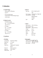
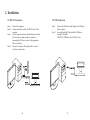
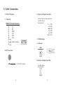
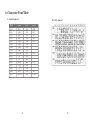
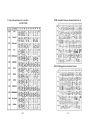
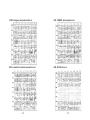
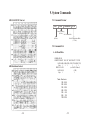
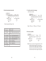
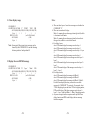
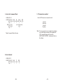
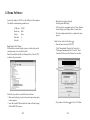
User's Manual
BD-202 Series
VFD Customer Display
Contents
1. Information.............................................................. 2
1.1 Standard Package................................................ 2
1.2 Optional Accessories........................................... 2
1.3 Specifications...................................................... 2
2. Installation............................................................... 4
2.1 RS-232 Connection............................................. 4
2.2 USB Connection................................................. 5
3. Cable Connections................................................... 6
3.1 RS-232 Interface................................................. 6
3.2 USB Interface...................................................... 7
4. Character Font Table.............................................. 8
5. System Commands................................................. 15
5.1 Command Format............................................... 15
5.2 Command List.................................................... 15
5.3 Transmit Method................................................ 21
6. Demo Software........................................................ 22
7. Command Modes.................................................... 24
-1-
1. Information
1.1 Standard Package
B. Electrical
· Display unit (RS-232 or USB interface)
· Support CD
· Power kit (for RS-232 interface)
to retrieve power DC 12V from switching power supply
inside the computer.
1.2 Optional Accessories
· Switch-Mode Power Supply
Input: AC 100V~240V, 50Hz~60Hz
Output: DC 9 V, 1A
· Power adapter
Input:
AC 110V, 60Hz
Output: DC 9 V, 1A
· Power adapter
Input:
AC 230V, 60Hz
Output: DC 9 V, 1A
Power Source
Power Consumption
Central Control Unit
Speed
DC 9V~12V (RS-232) or DC 5V
(USB)
2.5 Watts (RS-232) or 2.3Watts (USB)
CPU 8031BH
ROM 64K flash ROM
32K SRAM
29MHz
C. Physical
Dimensions (Panel)
Dimensions (Support)
Dimensions (Base)
Tilt Angle
Rotation Angle
Weight
Interface
Color
165W x 39D x 67H mm
72mm
187W x 84D x 25H mm
Max. 53
Max. 360
0.56Kg
RS-232 or USB
Black or beige
1.3 Specifications
D. Environmental
A. Tube Display
Customer Display
Display Pattern
Brightness
Character Type
Character Set
Character Size
Character Number
Vacuum Fluorescent Display
5 x 7 dot matrix
500 cd/m2
96 alphanumeric & 13 international
characters
9 different command sets
3.75W x 4.75H mm
2 x 20
-2-
Operating Temperature 0 ~40 (32 ~104 )
Storage Temperature -10 ~50 (14 ~122 )
Relative Humidity
0%~90% RH
-3-
2. Installation
2.1 RS-232 Connection
2.2 USB Connection
Step 1:
Step 2:
Step1:
Step 3:
Step 4:
Turn off the computer.
Connect the display cable to the RS-232 port of the
computer.
Set the connection between the bundled power kit and
the switch power supply inside the computer or
connecting the DC power source by the appropriate
DC power adapter.
Turn on the computer. The display will be on and
ready for receiving data.
-4-
Step 2:
Connect the USB cable of the display to the USB port
of the computer.
Insert the bundled CD and install the USB driver
through Utilities\BD202\CP2102_USBdriver\Check USB_Port.exe
-5-
3. Cable Connections
C. Interface of Display Panel Side
3.1 RS-232 Interface
Interface connector (display panel side)
6 pin Male-Header
Pin assignments:
1
TXD
DSR
RXD
DTR
GND
VCC
6
A. Cable-end
DSUB-9 Pin Female Connector
2
3
5
7
8
9
1
4
6
TX
RX
GND
CTS
RTS
VCC
3.2 USB Interface
5
1
9
6
Short Connection
A. Cable-end
USB
1 +5V
2 Data
3 +Data
4 GND
B. DC Power Jack
+
B. Interface of Display Panel Side
GND
+9~12VDC/500~1000mA
-6-
4 pin Male-Header
Pin assignments:
1 VCC
2 D3 D+
4 GND
-7-
4. Character Font Table
A. Control code set
HEX
00H
01H
02H
03H
04H
05H
06H
07H
08H
09H
0AH
0BH
0CH
0DH
0EH
0FH
B. U.S.A. font set
CODE
NULL
MD1
MD2
MD3
MD4
MD5
MD6
MD7
BS, Md8
HT
LF
HOM
CLR
CR
SLE1
RS,SLE2
-8-
HEX
10H
11H
12H
13H
14H
15H
16H
17H
18H
19H
1AH
1BH
1CH
1DH
1EH
1FH
CODE
DLE
DC1
DC2
DC3
DC4
CAN
ESC
SF1
US, SF2
-9-
C. International character selection
ASCII CODE
3DH: Standard Europe international font set
3EH: Multingual international font set
-10-
-11-
3FH: Portuguese international font set
41H: NORDIC internatinal font set
40H: Canadian French international font set
42H: RUSSIA font set
-12-
-13-
5. System Commands
43H: SLAVONIC Font set
5.1 Command Format
EOT
SOH
COMMAND
ETB
Start of Heading
(01 Hex)
See Command list
(04 Hex)
End of Transmission Block
(17 Hex)
5.2 Command List
A. Set Baud Rate
44H: Katakana font set
COMMAND: B
COMPUTER:EOT SOH 'B' 'BAUD RATE' 'N' ETB
ASCII (04H) (01H)(42H) (31H~37H) (4EH)(17H)
Byte 1
1
1
1
1
1
DISPLAY: ACK
(or NACK if failed)
ASCII (06H)
(15H)
Byte 1
1
Note: Baud rates
31H: 9600
32H: 4800
33H: 2400
34H: 1200
35H: 600
36H: 300
37H:19200
-14-
-15-
B. Select international code table
COMMAND: I
COMPUTER:EOT SOH 'I' 'CHAR' ETB
ASCII(04H)(01H)(49H)(30H~44H)(17H)
Byte 1
1
1
1
1
DISPLAY: ACK
(or NACK if failed)
ASCII (06H)
(15H)
Byte 1
1
C. Save the current view message
(Save Demo view data)
COMMAND: S
COMPUTER:EOT SOH 'S'
'Layer' ETB
ASCII(04H)(01H)(53H)(31H~33H)(17H)
Byte 1
1
1
1
1
DISPLAY: ACK
(or NACK if failed)
ASCII (06H)
(15H)
Byte 1
1
Note : International Character Code
Note : 31H: Layer 1 / 32H: Layer 2 / 33H: Layer 3
30H :
31H :
32H :
33H :
34H :
35H :
36H :
37H :
38H :
39H :
3AH :
U. S. A.
France
Germany
U. K.
Denmark I
Sweden
Italian
Spain
Japan
Norway
3BH :
3CH :
3DH :
3EH :
3FH :
40H :
41H :
42H :
43H :
44H :
Slavonic
Russia
Standard Europe International font set
Multingual International font set
Portuguese International font set
Canadian French International font set
Nordic International font set
Russia font set
Slavonic font set
Katakana font set
Denmark II
-16-
D. Set cursor position
COMMAND: P
COMPUTER: EOT SOH 'P'
'Position'
ETB
ASCII (04H) (01H) (50H) (31H~58H) (17H)
Byte 1
1
1
1
1
DISPLAY: ACK
(or NACK if failed)
ASCII (06H)
(15H)
Byte 1
1
Note: The cursor can be set to the position from 1 to 40
Position 1 means the upper left corner position.
Position 20 means the upper right corner position.
Position 21 means the lower left corner position.
Position 40 means the lower right corner position.
-17-
Note:
E. Clear display range
COMMAND: C
COMPUTER: EOT SOH 'C' 'START'
'END' ETB
ASCII (04H)(01H)(43H)(31H~58H)(31H~58H)(17H)
Byte 1
1
1
1
1
1
DISPLAY: ACK
(or NACK if failed)
ASCII (06H)
(15H)
Byte 1
1
Note: Some part of the current view messages can be
cleared by this COMMAND. It can start clearing
between position 1 and position 40.
F. Display the saved DEMO message
COMMAND: D
COMPUTER: EOT SOH 'D' 'Layer'
'Mode' ETB
ASCII (04H)(01H)(44H)(31H~37H)(31H~33H)(17H)
Byte 1
1
1
1
1
1
DISPLAY: ACK
(or NACK if failed)
ASCII (06H)
(15H)
Byte 1
1
-18-
a) There are three layers of saved view messages as described on
COMMAND "S"
b) There are two modes of display:
Mode 1 is running the saved messages from right to left, which
is a horizontal scroll mode.
Mode 2 is running the saved messages from the lower line to
the upper line, which is a vertical scroll mode.
c) For display layers:
select 31H means display the message saved on layer 1.
select 32H means display the message saved on layer 2.
select 33H means display the message saved on layer 1+ layer
2.
select 34H means display the message saved on layer 3.
select 35H means display the two messages saved on layer 1 +
layer 3.
select 36H means display the two messages saved on layer 2 +
layer 3.
select 37H means display all the messages saved on layer 1 +
layer 2 + layer 3.
d) For display modes,
select 31H means display the message with Mode 1.
select 32H means display the message with Mode 2.
select 33H means display the message with Mode 1+Mode 2.
For this Demo display function, you must have saved the
message by COMMAND "S" previously, For example, select
37H for displaying layers and select 33H for displaying modes,
DSP would display all the three messages saved on layer 1+
layer 2 + layer 3 with both Mode 1 + Mode 2 displaying modes.
e) Any new message from the computer would stop this Demo
display function and DSP would display that new message
from the computer.
-19-
G. Select the Command Mode
5.3 Transmission method
COMMAND: M
COMPUTER: EOT SOH
'M'
'Mode'
ETB
ASCII (04H) (01H) (4DH)(30H~38H) (17H)
Byte 1
1
1
1
1
DISPLAY: ACK
(or NACK if failed)
ASCII (06H)
(15H)
Byte 1
1
Note: Command Modes Selection
Each ASCII character is transmitted with
1 start bit
8 data bits
1 stop bit
No parity
Note: You may generate your own application software
to run the display according to the standard RS232C communication protocols and the
SOFTWARE CONTROL information listed on
this chapter.
H. Set all default
COMMAND: X
COMPUTER: EOT SOH
'X'
ASCII (04H) (01H) (58H)
Byte 1
1
1
-20-
ETB
(17H)
1
-21-
6. Demo Software
Connect the display to COM 1 or the USB port of the computer.
The default communication parameters are:
COM port:
Baud rate:
Parity:
Data bits:
Stop bit:
COM 1
9600
None
8
1
Note: Identify the USB port
USB interface customer display assigns a virtual serial port for
communications. Execute Start\Control
Panel\System\Hardware\Device Manager\Ports (Com & LPT)
to identify the port number.
Follow the steps below to install the demo software.
· Make sure the display is powered on and connected properly
to the computer.
· Insert the bundled CD and install the demo software through
Utilities\BD-202\setup.exe
-22-
· Run the demo software through
Start\Programs\BDConfig.
· Test the software commands, such as Cursor Position,
Screen Display, and Display Mode, by each index.
· Close the configuration utility to complete the setup
process.
Note: Set the symbol of the Euro ( )
· Run the demo software of BD-202.
· Click "International Character Set" and select
"Multingual international font". Press the "Send
Command" bottom on the Character Set window.
· The position of the Euro ( ) is Font: E, D5 (Hex).
-23-
7. Command Modes
Mode 1: EPSON Esc/POS mode
Command
Code Description Function
(hex)
HT
BS
US LF
LF
09
08
1F 0A
0A
US CR
1F 0D
CR
HOM
US B
CLR
CAN
US E n
ESC @
ESC R n
US MD1
US MD2
US MD3
ESC W
n s x1
y1 x2 y2
0D
0B
1F 42
1F 24 x y
X=1-20 y=01,02
0C
18
1F 45 n n=00-ff
1B 40
1B 52 n n=0~15
1F 01
1F 02
1F 03
1B 57 n s x1
y1 x2 y2
n=1,2,3,4 s=0, 1
US:
1F 3A
US ^ n m
1F 5E n m
00<=(n,m)<=ff
The command modes can be selected with the Demo Software.
Mode 0: BD-202 (Default)
Mode 1: EPSON Esc/POS
Mode 0: BD-202 mode
Command
Hexadecimal
Codes
Function
B
I
S
P
C
42H
49H
53H
50H
43H
D
44H
ESC G
ESC S
M
X
IBH 47H
IBH 53H
4DH
58H
Set baud rate and parity
Select international character set
Save the current view message
Set cursor position
Clear display message
Display the saved DEMO
message
Print ON command
Print OFF command
Select command mode
Set all default
-24-
US $ x y
Move cursor right
Move cursor left
Move cursor up
Move cursor down
Move cursor to right-most
position
Move cursor to left-most position
Move cursor to home position
Move cursor to bottom position
Move cursor to specified position
Clear display screen
Clear cursor line
Blink display screen
Initialize display
Select international character set
Specify overwrite mode
Specify vertical scroll mode
Specify horizontal scroll mode
Specify/cancel the window range
1<=x1<=x2<=20
1<=y1<=y2<=2
Set starting/ending position of
macro definition
Execute and quit macro
-25-