1
WADE-8022
Mini-ITX Board
User's Manual
Version 1.0
Copyright © Portwell, Inc., 2014. All rights reserved.
All other brand names are registered trademarks of their respective owners.
Preface
Table of Contents
How to Use This Manual
Chapter 1 System Overview.......................................................................................................1-1
1.1 Introduction ....................................................................................................... 1-1
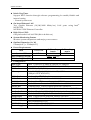
1.2 Check List........................................................................................................... 1-2
1.3 Product Specification........................................................................................ 1-2
1.3.1 Mechanical Drawing................................................................................ 1-4
1.4 System Architecture.......................................................................................... 1-6
Chapter 2 Hardware Configuration ...........................................................................................2-1
2.1 Jumper Setting ................................................................................................... 2-1
2.2 Connector Allocation...................................................................................... 2-10
Chapter 3 System Installation....................................................................................................3-1
3.1 Intel® Haswell Processor .................................................................................. 3-1
3.2 Main Memory .................................................................................................... 3-1
3.3 Installing the Mini-ITX Board Computer ...................................................... 3-2
3.3.1 Chipset Component Driver .................................................................... 3-2
3.3.2 Intel® Integrated Graphics Controller................................................... 3-3
3.3.3 Gigabit Ethernet Controller .................................................................... 3-3
3.3.4 Audio Controller ...................................................................................... 3-3
3.4 Clear CMOS Operation .................................................................................... 3-3
3.5 EC WDT.............................................................................................................. 3-4
3.6 EC GPIO ............................................................................................................. 3-6
Chapter 4 BIOS Setup Information............................................................................................4-1
4.1 Entering Setup - Launch System Setup.......................................................... 4-1
4.2 Main .................................................................................................................... 4-2
4.3 Configutation..................................................................................................... 4-3
4.4 Boot ................................................................................................................... 4-23
4.5 Security ............................................................................................................. 4-25
4.6 Save & Exit ....................................................................................................... 4-26
Chapter 5 Troubleshooting ........................................................................................................5-1
5.1 Hardware Quick Installation........................................................................... 5-1
5.2 BIOS Setting ....................................................................................................... 5-3
5.3 FAQ ..................................................................................................................... 5-4
Preface
How to Use This Manual
The manual describes how to configure your WADE-8022 system board to meet
various operating requirements. It is divided into five chapters, with each chapter
addressing a basic concept and operation of Mini-ITX Board.
Chapter 1: System Overview. Presents what you have in the box and give you an
overview of the product specifications and basic system architecture for this series
model of Mini-ITX Board.
Chapter 2: Hardware Configuration. Show the definitions and locations of Jumpers
and Connectors that you can easily configure your system.
Chapter 3: System Installation. Describes how to properly mount the CPU, main
memory and Compact Flash to get a safe installation and provides a programming
guide of Watch Dog Timer function.
Chapter 4: BIOS Setup Information. Specifies the meaning of each setup
parameters, how to get advanced BIOS performance and update new BIOS. In
addition, POST checkpoint list will give users some guidelines of trouble-shooting.
Chapter 5: Troubleshooting. Provide various of useful tips to quickly get
WADE-8022 running with success. As basic hardware installation has been
addressed in Chapter 3, this chapter will basically focus on system integration issues,
in terms of backplane setup, BIOS setting, and OS diagnostics.
The content of this manual is subject to change without prior notice. These changes
will be incorporated in new editions of the document. The vendor may make
supplement or change in the products described in this document at any time.
System Overview
Chapter 1
System Overview
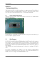
1.1 Introduction
Portwell Inc., a world-leading innovator in the Industrial PC (IPC) market and a
member of the Intel® Embedded and Communications Alliance (Intel® ECA),
announced today the Portwell WADE-8022 adopting the Mini-ITX form factor. The
WADE-8022 of the Intel® platform will provide high performance and flexibility for
functional expansion, such as Gaming, Kiosk, DS, Medical, Defense, Industrial
automation and control applications.
Haswell mobile processors is the next major architecture from Intel®. The
WADE-8022 supports the latest Intel® Haswell mobile processors in BGA1364
package which has memory and PCI Express controller integrated to support
2-channel DDR3L memory and PCI Express 3.0 lanes providing great graphics
performance. Intel® Haswell mobile processor is one of the most powerful and energy
efficient CPU in the world. Portwell have taken advantage of such technology to
furnish a series of products that can meet multiple industrial requirements such as
cost-effective of CPU performance or industrial systems.
WADE-8022 is based on the Intel® Haswell mobile processor with Intel® QM87
chipset.
The Intel® QM87 Express Chipset, when combined with a processor from the Intel®
Dual Core/Quad Core mobile processor family, delivers smart security, cost saving
manageability, and Intel® ligent performance for business platforms. WADE-8022 is
the first Portwell off-the-shelf product for by Intel® QM87 Express Chipset, it can be
an embedded solution and a good platform for customer to integrate it to the
embedded system.
WADE-8022 showcased one of Portwell upcoming motherboard for the Intel®’s
Haswell mobile processors. The WADE-8022 is based on the forthcoming Intel®
QM87 chipset and supports the new BGA1364 type. This board has lots of features,
including supports total 4x SATA 6.0 Gbps storage specification , allows RAID 0/1/5
and 10. supports the latest PCIe 3.0 (one PCI-Express x16 slot) devices for double
speed and bandwidth which enhances system performance, two long-DIMM
memory slot for DDR3L SDRAM up to 16GB, support total 10 USB ports (4x USB 3.0
on rear I/O, 6x USB 2.0 on board header), VGA / HDMI / DVI-D / DP / LVDS, two
Gigabit Ethernet and Dual mini-PCIe slot support mSATA and normal storage.
WADE-8022 User’s Manual
1-1
System Overview
1.2
Check List
The WADE-8022package should cover the following basic items
9
9
9
9
One WADE-8022Mini-ITX Main Board
One SATA Cable
One I/O Shield bracket
One Installation Resources CD-Title
If any of these items is damaged or missing, please contact your vendor and keep all
packing materials for future replacement and maintenance.
1.3
Product Specification
z Main Processor
Intel® mobile BGA processor
z Chipset
Intel® QM87 chipset
z System BIOS
AMI BIOS
z Main Memory
Two 204 -pin DDR3 SODIMM socket support DDR3L up to 16GB dual channel
1333/1600 MHz memory
z Expansion Interface
One PCIex16
- Two Mini-PCIe slot(support mSATA and normal SSD storage)
- One PCIe x1 gold finger(include 2x PCI x1 signal)
z SATA Interface
Four SATA 6Gb ports
z Serial Port
Support total six comports(one RS232 and one RS232/422/485 on rear I/O,three
RS232 and one RS232/422/485 on board header)
z USB Interface
Support Ten USB (Universal Serial Bus) ports, four USB 3.0 ports on rear I/O and
six USB 2.0 ports on board header for internal devices
z Audio Interface
Line-Out Audio Jack on Rear I/O, Mic-In, Line-In on board header
z Real Time Clock/Calendar (RTC)
Support Y2K Real Time Clock/Calendar
WADE-8022 User’s Manual
1-2
System Overview
z Watch Dog Timer
Support WDT function through software programming for enable/disable and
interval setting
- General system reset
z On-board Ethernet LAN
Two Gigabit Ethernet (10/100/1000 Mbits/sec) LAN ports using Intel®
WGI217LM
WGI210AT GbE Ethernet Controller
z High Drive GPIO
One pin-header for 8 bit GPIO(4bit in & 4bit out)
z System Monitoring Feature
Monitor system temperature and major power sources.
z Outline Dimension (L x W)
170mm(6.69’’) x 170mm(6.69’’)
z Power Requirements
Item
Power ON
System +12V
USB Loading Test (2.0)
USB Loading Test (3.0)
1.71 A
z Configuration
CPU Type
SBC BIOS
EC Version
Memory
Full Loading
10Min
1.98 A
4.86 V/ 510 mA
4.82 V/ 970 mA
Full Loading
30Min
2.23 A
Intel® Celeron CPU 2000E @ 2.20GHz L3: 2Mbytes
Portwell, Inc. WADE-8022 TEST BIOS ( 40820T00 )
40717T00 ( 07/17/2014 )
WARIS DDR3L SO-DIMM 1600 1.35V/8GB*1
(Skhynix H5TC4G83AFR )
VGA Card
VGA Driver
LAN Card
LAN Driver
LAN Card
LAN Driver
Onboard Intel® HD Graphics
Intel® HD Graphics Version: 10.18.10.3496
Onboard Intel® Ethernet Connection I217-LM
Intel® Ethernet Connection I217-LM Version: 12.11.96.1
Onboard Intel® I210AT Gigabit Network Connection
Intel® I210AT Gigabit Network Connection Version: 12.11.97.0
Audio Card
Audio Driver
Chip Driver
USB 3.0 Driver
SATA HDD
DVDROM
Power Supply
Onboard Realtek ALC886 High Definition Audio
Realtek ALC886 High Definition Audio Version: 6.0.1.7246
Intel® Chipset Device Software Version: 9.4.0.1027
Intel® USB3.0 eXtensible Host Controller Version: 6.2.9200.16384
WD WD1002FAEX 1TB
LION-ON IHAS324 DVD-ROM
Seasonic SSA-0651-1 DC 12V
WADE-8022 User’s Manual
1-3
System Overview
z Operating Temperature
0 °C ~ 60 °C
z Storage temperature
-20 ~ 80 °C
z Relative Humidity
0% ~ 90%, non-condensing
1.3.1 Mechanical Drawing
WADE-8022 User’s Manual
1-4
System Overview
WADE-8022 User’s Manual
1-5
System Overview
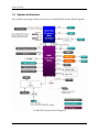
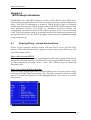
1.4 System Architecture
All of details operating relations are shown in WADE-8022 System Block Diagram.
WADE-8022 System Block Diagram
WADE-8022 User’s Manual
1-6
Hardware Configuration
Chapter 2
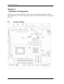
Hardware Configuration
This chapter gives the definitions and shows the positions of jumpers, headers
and connectors. All of the configuration jumpers on WADE-8022 are in the proper
position.
2.1
Jumper Setting
WADE-8022 User’s Manual
2-1
Hardware Configuration
WADE-8022 User’s Manual
2-2
Hardware Configuration
Jump Setting List
is mean default
JP1: GPIO Power select Connector
PIN No.
1-2
2-3
Signal Description
5V
3V (Default) JP2: Dual channel LVDS VDD voltage Select
PIN No.
1-2
5-6
Signal Description
VDD voltage 3.3V (Default) VDD voltage 5V
JP3: LVDS BL Enable voltage Select
PIN No.
1-3, 2-4
1-3, 4-6
3-5,2-4
3-5,4-6
Signal Description
5V, Active High (Default) 12V, Active High
5V, Active Low
12V, Active Low
JP4: WDT Function Select
PIN No.
1-2 short
1-2 open
Signal Description
WDT Function enable (Default)
WDT Function disable
JP5: ATX / AT Mode Select
PIN No.
1-2 short
1-2 open
Signal Description
ATX emulation AT mode
ATX mode WADE-8022 User’s Manual
2-3
Hardware Configuration
J9: Audio MIC/Line-in/Line-out Connector
PIN No.
1
3
5
7
Signal Description
MIC- in Left Channel
Analog Ground
Line-out Left Channel
Line-out Right Channel
PIN No.
2
4
6
8
Signal Description
Line-in Left Channel
Line-in Right Channel
Analog Ground
MIC- in Right Channel
J10: ATX 4Pin 12V Power Connector
PIN No.
1
2
3
4
Signal Description
Ground
Ground
+12V
+12V
J11: 8Bit GPIO Connector
PIN No.
1
3
5
7
9
Signal Description
LPC_GPJ0
LPC_GPJ1
LPC_GPJ2
LPC_GPJ3
GND
PIN No.
2
4
6
8
10
Signal Description
LPC_GPE0
LPC_GPE7
LPC_GPC0
LPC_GPG0
VCC
J13: LVDS Power Connector
PIN No.
1
2
3
4
5
Signal Description
VCC
BL_BRIGHT
+12V
Ground
BL_ENABLE
WADE-8022 User’s Manual
2-4
Hardware Configuration
J14: TPM(Trusted Platform Module) Connector
PIN No.
1
3
5
7
9
11
13
15
17
19
Signal Description
PCLK_TPM
LFRAME#
SIO2_PLTRST#
LAD3
VCC3
LAD0
SMB_CLK_MAIN
3VSB
GND
LPCPD#
PIN No.
2
4
6
8
10
12
14
16
18
20
Signal Description
GND
N/C
VCC
LAD2
LAD1
GND
SMB_DATA_MAIN
SERIRQ
N/C
N/C
J15: Dual channel LVDS Connector
PIN No.
1
3
5
7
9
11
13
15
17
19
21
23
25
27
29
Signal Description
VDD
LCD1DO0+
LCD1DO1+
LCD1DO2+
LCD1DO3+
LCD1CLK+
LCLK1
Ground
LCD2DO0+
LCD2DO1+
LCD2DO2+
LCD2DO3+
LCD2CLK+
N/C
Ground
WADE-8022 User’s Manual
PIN No.
2
4
6
8
10
12
14
16
18
20
22
24
26
28
30
Signal Description
VDD
LCD1DO0LCD1DO1LCD1DO2LCD1DO3LCD1CLKLDATA1
Ground
LCD2DO0LCD2DO1LCD2DO2LCD2DO3LCD2CLKN/C
Ground
2-5
Hardware Configuration
J16/J17/J18/J19: COM3/COM4/COM5/COM6 Serial Port Connector
PIN No.
1
3
5
7
9
Signal Description
DCD (Data Carrier Detect)
TXD (Transmit Data)
PIN No.
2
4
GND (Ground)
RTS (Request to Send)
RI (Ring Indicator)
6
8
10
Signal Description
RXD (Receive Data)
DTR (Data Terminal
Ready)
DSR (Data Set Ready)
CTS (Clear to Send)
N/C
J20: Clear CMOS
PIN No.
1-2
2-3
Signal Description
Normal Clear CMOS
J22/J26: SATA Power Connector
Pin No.
1
2
3
4
Signal Description
+12V
GND
GND
VCC
WADE-8022 User’s Manual
2-6
Hardware Configuration
J23/J24/J25: External USB Connector
PIN No.
Signal Description
1
5V Dual
3
USB5
USB+
7
Ground
9
PIN No.
2
4
6
8
10
Signal Description
5V Dual
USBUSB+
Ground
N/C
J27: SMBus Connector
PIN No.
1
2
3
4
5
Signal Description
SMBus_CLK
N/C
Ground
SMBus_DAT
+5V
J32: SYSTEM FAN Power Connector
PIN No.
1
2
3
Signal Description
Ground
Fan speed control
Fan on/off output
WADE-8022 User’s Manual
2-7
Hardware Configuration
J37: Front Panel System Connector
PIN No.
1
3
5
7
9
11
13
15
Signal Description
PWR_LED(+)
PWR_LED(-)
J4 LAN1_ACT(+)
J4 LAN1_LINK(-)
J5 LAN2_LINK(-)
J5 LAN2_ACT(+)
HDD_LED(+)
HDD_LED(-)
PIN No.
2
4
6
8
10
12
14
16
Signal Description
Speaker(+)
GND
N /C
Speaker(-)
GND
Power Button
RESET Button
GND
J38: CPU FAN Power Connector
PIN No.
1
2
3
4
Signal Description
Ground
+12V
Fan on/off output
Fan Speed control
J39:PS/2 Keyboard/Mouse Pin Header
PIN No.
1
3
5
7
9
Signal Description
Mouse Data
N/C
Ground
PS2 Power
Mouse Clock
WADE-8022 User’s Manual
PIN No.
2
4
6
8
10
Signal Description
Keyboard Data
N/C
Ground
PS2 Power
Keyboard Clock
2-8
Hardware Configuration
J41: SPI Bus Select Header
PIN No.
1-3, 2-4, 7-9, 8-10
3-5, 4-6, 9-11, 10-12
Signal Description
CFEX
Normal SW1: LVDS GPIO Switch Select
ON : 0 ; OFF : 1
Default : 0001
Pin No.
1
2
3
4
Signal Description
GP0
GP1
GP2
GP3
WADE-8022 User’s Manual
2-9
Hardware Configuration
2.2
Connector Allocation
I/O peripheral devices are connected to the interface connectors.
Connector Function List
Connector
Function
Remark
J1
DC Jack
J2
Audio Line Out Connector
J3
Serial port Connector (Top-COM2, COM2 Support 232/422/485
Bot-COM1)
J4
Display Port Connector (DP port)
J5
DVI-I Connector
Support Dual (DVI-D,VGA)
Link
J6
HDMI Connector
J7
USB/100+Giga Lan Connector
(LAN2) I210IT
J8
USB/100+Giga Lan Connector
(LAN1) I217LM
J9
Audio MIC/Line-in/
Line-out Connector
J10
ATX 4Pin 12V Power Connector
J11
8Bit GPIO Connector
J13
LVDS Power Connector
J14
TPM(Trusted Platform Module)
Connector
J15
Dual channel LVDS Connector
J16、J17、J18、 COM3/COM4/COM5/COM6
Serial Port Connector
J19
J20
Clear CMOS Select HEADER
J21
PCI-E x16 Slot
Support PCI-E Gen3
J22、J26
SATA Power Connector
J23、J24、J25 External USB Connector
J27
SMBus Connector
J28
Mini PCIe Slot
Only Support Mini PCIe
J29
Mini PCIe Slot
Only Support mSATA
J30、J31
SO-DIMM Slot
Only Support
DDR3L Memory
J32
System FAN Power Connector
J33、J34、J35、 SATA Connector(6Gb/s)
J36
J37
Front Panel System Connector
J38
CPU FAN Power Connector
J39
PS/2 Keyboard/Mouse Pin Header
WADE-8022 User’s Manual
2-10
Hardware Configuration
J40
J41
CFEX Card slot
SPI Select HEADER
WADE-8022 User’s Manual
2-11
System Installation
Chapter 3
System Installation
This chapter provides you with instructions to set up your system. The additional
information is enclosed to help you set up onboard PCI device and handle Watch
Dog Timer (WDT) and operation of GPIO in software programming.
3.1
Intel® Haswell Processor
The Main Processor of the WADE-8022 is Intel® Celeron Haswell 2000E 2.2GHz
Processor (BGA Type)
WADE-8022 can support 4th Generation Mobile Celeron/Core Haswell i3/i5/i7
Processors (BGA Type) by optional.
3.2
Main Memory
WADE-8022 provide 2 x 204 pin DIMM sockets (Dual Channel) which supports
Dual channel 1333 DDR3L-SO-DIMM (1.35V) Non-ECC (Error Checking and
Correcting), non-register functions as main memory. The maximum memory can
be up to 16GB. Memory clock and related settings can be detected by BIOS via
SPD interface.
The 2 DIMMs per channel only supported in Quad-Core package (1333 MT/s
only)
For system compatibility and stability, do not use memory module without
brand. Memory configuration can be set to either one double-sided DIMM in one
DIMM socket or two single-sided DIMM in both sockets.
WADE-8022 User’s Manual
3-1
System Installation
Beware of the connection and lock integrity from memory module to socket.
Inserting improperly it will affect the system reliability.
Before locking, make sure that all modules have been fully inserted into the card
slots.
Note:
To insure the system stability, please do not change any of DRAM parameters in
BIOS setup to modify system the performance without acquired technical
information.
3.3
Installing the Mini-ITX Board Computer
To install your WADE-8022 into standard chassis or proprietary environment,
please perform the following:
Step 1: Check all jumpers setting on proper position
Step 2: Install and configure CPU and memory module on right position
Step 3: Place WADE-8022 into the dedicated position in the system
Step 4: Attach cables to existing peripheral devices and secure it
WARNING
Please ensure that SBC is properly inserted and fixed by mechanism.
Note:
Please refer to section 3.3.1 to 3.3.4 to install INF/VGA/LAN/Audio drivers.
3.3.1
Chipset Component Driver
WADE-8022 uses Intel® QM87 Lynx Point chipset. It’s a new chipset that some old
operating systems might not be able to recognize. To overcome this compatibility
issue, for Windows Operating Systems such as Windows 7, please install its INF
before any of other Drivers are installed. You can find very easily this chipset
component driver in WADE-8022 CD-title.
WADE-8022 User’s Manual
3-2
System Installation
3.3.2
Intel® Integrated Graphics Controller
WADE-8022 uses Intel® PCH integrated graphic chipset to gain an outstanding
graphic performance. WADE-8022 supports DP (3200 x 2000 resolution), HDMI
(4096 x 2304 resolution), LVDS (18/24bit single & Dual port, 1920x1200
resolution)from onboard Shark Bay BGA processor, DVI-I (DVI+VGA, 1920 x
1200 resolution) from QM87 PCH display output. Processor integrated 3D
graphics Media Accelerator . Supports DX11.1, OpenGL 3.1, MPEG-2, Shader
Model 4.0. WADE-8022 can support triple display output.
Drivers Support
Please find the Graphic drivers in the WADE-8022 CD-title. Drivers support
Win7.
3.3.3
Gigabit Ethernet Controller
Drivers Support
Please find Intel® WGI217LM and WGI210AT LAN drivers in /Ethernet directory
of WADE-8022 CD-title. The drivers support Win7.
3.3.4
Audio Controller
Please find ALC886 (High Definition Audio driver) form WADE-8022 CD-title.
The drivers support Win7.
3.4
Clear CMOS Operation
The following table indicates how to enable/disable Clear CMOS Function
hardware circuit by putting jumpers at proper position.
J20: Clear CMOS
PIN No.
1-2
2-3
Signal Description
Normal
Clear CMOS
WADE-8022 User’s Manual
3-3
System Installation
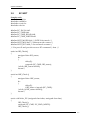
3.5
EC WDT
Sample code:
#include <stdio.h>
#include <stdlib.h>
#include <conio.h>
#include <dos.h>
#define EC_DATA 0x62
#define EC_CMD 0x66
#define EC_CMD_READ 0x80
#define EC_CMD_WRITE 0x81
#define WDT_MODE 0x06 /* WDT Select mode. */
#define WDT_MIN 0x07 /* Minute mode counter */
#define WDT_SEC 0x08 /* Second mode counter */
/* Use port 62 and port 66 to access EC command / data. */
static int IBF_Check()
{
unsigned char IBF_status;
do
{
delay(2);
outportb (EC_CMD, IBF_status);
} while (IBF_status & 0x02);
return 1;
}
static int OBF_Check ()
{
unsigned char OBF_status;
do
{
delay(2);
OBF_status = inportb (EC_CMD);
} while (!(OBF_status & 0x01));
return 1;
}
static void Write_EC (unsigned char index, unsigned char data)
{
IBF_Check ();
outportb (EC_CMD, EC_CMD_WRITE);
IBF_Check ();
WADE-8022 User’s Manual
3-4
System Installation
outportb (EC_DATA, index);
IBF_Check ();
outportb (EC_DATA, data);
}
static unsigned char Read_EC (unsigned char address)
{
unsigned char data;
IBF_Check ();
outportb (EC_CMD, EC_CMD_READ);
IBF_Check ();
outportb (EC_DATA, address);
OBF_Check();
data = inportb (EC_DATA);
return data;
}
void EC_WDT_Trigger ()
{
/* WDT Counter */
Write_EC (WDT_SEC, 0x05);
/* if use minute mode */
/* Write_EC (WDT_MIN, 0x05); */
/* 0x01 is second mode */
/* 0x03 is minute mode */
Write_EC (WDT_MODE, 0x01);
}
int main ()
{
int i;
EC_WDT_Trigger ();
for (i = 0; i < 5; i++)
{
printf ("Reset counter ...................%d\n", 5 - i);
delay (1000);
}
return 0;
}
WADE-8022 User’s Manual
3-5
System Installation
3.6
EC GPIO
Sample code:
#include <stdio.h>
#include <stdlib.h>
#include <conio.h>
#include <dos.h>
#define EC_DATA 0x62
#define EC_CMD 0x66
#define EC_CMD_READ 0x80
#define EC_CMD_WRITE 0x81
#define GPIO_DIR 0x2B
#define GPIO_DATA 0x2C
static void Write_EC (unsigned char index, unsigned char data)
{
sleep(1);
outportb (EC_CMD, EC_CMD_WRITE);
sleep(1);
outportb (EC_DATA, index);
sleep(1);
outportb (EC_DATA, data);
}
static unsigned char Read_EC (unsigned char address)
{
unsigned char data;
sleep(1);
outportb (EC_CMD, EC_CMD_READ);
sleep(1);
outportb (EC_DATA, address);
sleep(1);
data = inportb (EC_DATA);
return data;
}
int main ()
{
unsigned char d2;
printf("\n\n");
printf("WADE-8079 GPIO TEST Program v1.0\n");
printf("Please short the following pins with 2.54mm-pitched jumper on
JP8\n");
WADE-8022 User’s Manual
3-6
System Installation
printf("GPIO1 ---- GPIO2\n");
printf("GPIO3 ---- GPIO4\n");
printf("GPIO5 ---- GPIO6\n");
printf("GPIO7 ---- GPIO8\n");
printf("GND xxxx Vcc <==PWR/GND
them!\n\n");
printf("LED Test Begins...\n");
pins,
DO
NOT
short
/* Set GPIO Port In/Out mode */
Write_EC (GPIO_DIR, 0x00);
sleep (2);
printf("Write_EC mode 0x00\n");
/* Set Low or High */
Write_EC (GPIO_DATA, 0xFF);
printf("Write_EC data 0xFF\n");
sleep (2);
/* Set GPIO Port In/Out mode */
Write_EC (GPIO_DIR, 0x00);
sleep (2);
printf("Write_EC mode 0x00\n");
/* Set Low or High */
Write_EC (GPIO_DATA, 0x00);
printf("Write_EC data 0x00\n");
sleep (2);
return 0;
}
WADE-8022 User’s Manual
3-7
BIOS Setup Information
Chapter 4
BIOS Setup Information
WADE-8022 uses AMI BIOS structure stored in Flash ROM. These BIOS has a
built-in Setup program that allows users to modify the basic system configuration
easily. This type of information is stored in CMOS RAM so that it is retained
during power-off periods. When system is turned on, WADE-8022 communicates
with peripheral devices and checks its hardware resources against the
configuration information stored in the CMOS memory. If any error is detected,
or the CMOS parameters need to be initially defined, the diagnostic program will
prompt the user to enter the SETUP program. Some errors are significant enough
to abort the start up.
4.1
Entering Setup - Launch System Setup
Power on the computer and the system will start POST (Power On Self Test)
process. When the message below appears on the screen, press <Del> key will
enter BIOS setup screen.
Press <Del> to enter SETUP
If the message disappears before responding and still wish to enter Setup, please
restart the system by turning it OFF and On or pressing the RESET button. It can
be also restarted by pressing <Ctrl>, <Alt>, and <Delete> keys on keyboard
simultaneously.
Press <F1> to Run SETUP or Resume
The BIOS setup program provides a General Help screen. The menu can be easily
called up from any menu by pressing <F1>. The Help screen lists all the possible
keys to use and the selections for the highlighted item. Press <Esc> to exit the
Help screen.
WADE-8022 User’s Manual
4-1
BIOS Setup Information
4.2
Main
Use this menu for basic system configurations, such as time, date etc.
BIOS Information, Memory Information
These items show the firmware and memory specifications of your system. Read
only.
System Date
The date format is <Day>, <Month> <Date> <Year>. Use [+] or [-] to configure
system Date.
System Time
The time format is <Hour> <Minute> <Second>. Use [+] or [-] to configure
system Time.
WADE-8022 User’s Manual
4-2
BIOS Setup Information
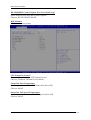
4.3
Configutation
Use this menu to set up the items of special enhanced features.
CPU Configuration
CPU Configuration Parameters
WADE-8022 User’s Manual
4-3
BIOS Setup Information
Active Processor Cores
Number of cores to enable in each processor package
Choices: All, 1.
Intel® Virtualization Technology
When enabled, a VMM can utilize the additional hardware capabilities provided
by Vanderpool Technology.
Choices: Disabled, Enabled.
EIST
Enable/Disable Intel® SpeedStep.
Choices: Disabled, Enabled.
CPU C states
Enable or disable CPU C states
Choices: Disabled, Enabled.
Enhanced C1 states (CPU C states Enabled)
Enhance C1 state
Choices: Disabled, Enabled.
CPU C3 Report (CPU C states Enabled)
Enable/Disable CPU C3 report to OS
Choices: Disabled, Enabled.
CPU C6 Report (CPU C states Enabled)
Enable/Disable CPU C6 report to OS
Choices: Disabled, Enabled.
CPU C7 Report (CPU C states Enabled)
Enable/Disable CPU C7 report to OS
Choices: Disabled, CPU C7, CPU C7s.
WADE-8022 User’s Manual
4-4
BIOS Setup Information
Chipset Configuration
Configuration Chipset feature
High Precision Timer
Enable or Disable the High Precision Event Timer.
Choices: Disabled, Enabled.
Azalia
Control Detection of the Azalia Device.
Disabled = Azalia will be unconditionally disabled.
Enabled = Azalia will be unconditionally Enabled.
Choices: Disabled, Enabled.
Port 80h Redirection
Control where the Port 80h cycles are sent
[LPC BUS] Forward I/O Port 80 to LPC
[PCIE BUS] Forward I/O Port 80 to PCIE Subtractive device
Choices: LPC BUS, PCIE BUS.
WADE-8022 User’s Manual
4-5
BIOS Setup Information
AMT Configuration
Configure Active Management Technology Parameters
Intel® AMT
Enable/Disable Intel® Active management technology BIOS Extension
Note: iAMT H/W is always enabled.
This option just controls the BIOS extension execution. If enabled, this requires
additional firmware in the SPI device
Choices: Disabled, Enabled.
Un-configure ME
OEMFlag Bit 15: Un-configure ME without password.
Choices: Disabled, Enabled.
Disable ME
Set ME to Soft Temporary Disabled.
Choices: Disabled, Enabled.
WADE-8022 User’s Manual
4-6
BIOS Setup Information
Memory Configuration
Memory Configuration Parameters (Read Only)
LAN Configuration
Configuration On Board LAN device.
WADE-8022 User’s Manual
4-7
BIOS Setup Information
Launch PXE OpROM policy
Controls the execution of UEFI and Legacy PXE OpROM
Choices: Disabled, UEFI only, Enabled.
Intel® LAN I217 Controller
Enable or disable onboard NIC.
Choices: Enabled, Disabled.
Wake on LAN I217
Enable or disable integrated LAN to wake the system. (The Wake On LAN cannot
be disabled if ME is on at Sx state.)
Choices: Enabled, Disabled.
Intel® LAN I210 Controller
Enable or disable onboard NIC.
Choices: Enabled, Disabled.
Wake on LAN I210
Enable or disable integrated LAN to wake the system. (The Wake On LAN cannot
be disabled if ME is on at Sx state.)
Choices: Enabled, Disabled.
Graphic Configuration
Configuration Graphics Settings
WADE-8022 User’s Manual
4-8
BIOS Setup Information
Primary Display
Select which of IGFX/PEG/PCI Graphics device should be Primary Display Or
select SG for Switchable Gfx.
Choices: Auto, IGFX, PEG, PCIE.
Primary PCIE
Select PCIE4/PCIE5 Graphics device should be Primary PCIE.
Choices: Auto, PCIE4, PCIE5.
Aperture Size
Select the Aperture Size.
Choices: 128MB, 256MB, 512MB.
DVMT Pre-Allocated
Select DVMT 5.0 Pre-Allocated (Fixed) Graphics Memory size used by the
Internal Graphics Device.
Choices: 32M, 64M, 96M, 128M, 160M, 192M, 224M, 256M, 288M, 320M, 352M,
384M, 416M, 448M, 480M, 512M, 1024M.
DVMT Total Gfx Mem
Select DVMT 5.0 Total Graphic Memory size used by the Internal Graphic device.
Choices: 128M, 256MB, MAX.
Primary IGFX Boot Display
Select the Video Device which will be activated during POST. This has no effect if
external graphics present.
Secondary boot display will appear based on your selection. VGA modes will be
supported only on primary display.
Choices: VBIOS Default, VGA, DP, LVDS, DVI HDMI.
Secondary IGFX Boot Display
Select Secondary IFGX Boot Display Device.
Choices: Disabled, DP, LVDS, DVI, HDMI.
WADE-8022 User’s Manual
4-9
BIOS Setup Information
PCI/PCIE Configuration
PCI, PCI-X and PCI Express Settings.
PCI Latency Timer
Value to be programmed into PCI Latency Timer Register
Choices: 32 PCI Bus Clocks, 64 PCI Bus Clocks, 96 PCI Bus Clocks, 128 PCI Bus
Clocks, 160 PCI Bus Clocks, 192 PCI Bus Clocks, 224 PCI Bus Clocks, 248 PCI Bus
Clocks.
Maximum Payload
Set Maximum Payload of PCI Express Device or allow System BIOS to select the
value.
Choices: Auto, 128 Bytes, 256 Bytes, 512 Bytes, 1024 Bytes, 2048 Bytes, 4096 Bytes.
Maximum Read Request
Set Maximum Read Request size of PCI Express Device or allow System BIOS to
select the value.
Choices: Auto, 128 Bytes, 256 Bytes, 512 Bytes, 1024 Bytes, 2048 Bytes, 4096 Bytes.
WADE-8022 User’s Manual
4-10
BIOS Setup Information
CPU PCI Express Configuration
CPU PCI Express Configuration settings
PEG0 – Gen X
Configure PEG0 B0:D1:F0 Gen1-Gen3
Choices: Auto, Gen1, Gen2, Gen3
PEG0 – ASPM
Control ASPM support for the PEG Device. This has no effect if PEG is not the
currently active device.
Choices: Disabled, Auto, ASPM L0s, ASPM L1, ASPM L0sL1.
PEG1 – Gen X
Configure PEG1 B0:D1:F1 Gen1-Gen3
Choices: Auto, Gen1, Gen2, Gen3
PEG1 – ASPM
Control ASPM support for the PEG Device. This has no effect if PEG is not the
currently active device.
Choices: Disabled, Auto, ASPM L0s, ASPM L1, ASPM L0sL1.
PEG2 – Gen X
Configure PEG2 B0:D1:F2 Gen1-Gen3
Choices: Auto, Gen1, Gen2, Gen3
WADE-8022 User’s Manual
4-11
BIOS Setup Information
PEG2 – ASPM
Control ASPM support for the PEG Device. This has no effect if PEG is not the
currently active device.
Choices: Disabled, Auto, ASPM L0s, ASPM L1, ASPM L0sL1.
Enable PEG
To enable or disable the PEG
Choices: Disabled, Enabled, Auto.
PCH PCI Express Configuration
PCH PCI Express Configuration settings
WADE-8022 User’s Manual
4-12
BIOS Setup Information
PCI Express Root Port 1-5, Port8
PCI Express Root Port 1-5 Settings Port 1-5, Port8 (x1)
PCI Express Root Port 1-5, Port8
Control the PCI Express Root Port
Choices: Enabled, Disabled.
ASPM
PCI Express Active State Power Management settings
Choices: Disabled, L0s, L1, L0sL1, Auto
PCIe Speed
Select PCI Express port speed.
Choices: Auto, Gen1, Gen2.
WADE-8022 User’s Manual
4-13
BIOS Setup Information
SATA Configuration
SATA Device Options Settings
SATA Controller(s)
Enable or disable SATA Device.
Choices: Enabled, Disabled.
WADE-8022 User’s Manual
4-14
BIOS Setup Information
SATA Mode Selection
Determines how SATA controller(s) operate.
Choices: IDE, AHCI, RAID.
SATA Controller Speed
Indicates the maximum speed the SATA controller can support.
Choices: Default, Gen1, Gen2, Gen3.
Alternate ID (RAID Mode only)
Report alternate Device ID
Choices: Enabled, Disabled.
Port 0-5
Enable or Disable SATA Port
Choices: Disabled, Enabled.
Hot Plug
Designates this port as Hot Pluggable
Choices: Disabled, Enabled.
Mechanical Presence Switch (For Serial ATA Port 0-3 only)
Controls reporting if this port has an Mechanical Presence Switch.
Note: Requires hardware support.
Choices: Disabled, Enabled.
External SATA
External SATA Support
Choices: Disabled, Enabled.
SATA Device Type
Identify the SATA Port is connected to Solid State Drive or Hard Disk Drive.
Choices: Hard Disk Drive, Solid State Drive.
WADE-8022 User’s Manual
4-15
BIOS Setup Information
USB Configuration
USB Configuration Parameters
Legacy USB Support
Enables Legacy USB support. AUTO option disables legacy support if no USB
devices are connected. DISABLE option will keep USB devices available only for
EFI applications.
Choices: Enabled, Disabled, Auto.
XHCI Hand-Off
This is a workaround for OSes without XHCI hand-off support. The XHCI
ownership change should claim by XHCI driver.
Choices: Enabled, Disabled.
EHCI Hand-Off
This is a workaround for OSes without EHCI hand-off support. The EHCI
ownership change should claim by EHCI driver.
Choices: Disabled, Enabled.
USB Mass Storage Driver Support
Enable/Disable USN Mass Storage Driver Support.
Choices: Disabled, Enabled.
WADE-8022 User’s Manual
4-16
BIOS Setup Information
PCH USB Configuration
PCH USB Configuration settings
USB Port #0-11
Disable USB Port
Choices: Disabled, Enabled.
WADE-8022 User’s Manual
4-17
BIOS Setup Information
Power Control Configuration
System Power Control Configuration Parameters
Enable Hibernation
Enables or Disables System ability to Hibernate (OS/S4 Sleep State). This option
may be not effective with some OS.
Choices: Disabled, Enabled.
ACPI Sleep State
Select the ACPI Sleep state the system will enter when the SUSPEND button is
pressed.
Choices: S3 only (Suspend to RAM).
Power Loss Function
Control SIO Power Loss Function, ON is always ON, OFF is always OFF, Last
state will depends on last power state.
Choices: Always Off, Always On, Last State.
Wake system with Fixed Time
Enable or disable system wake on alarm event. When enabled, System will wake
on the hr::min::sec specified.
Choices: Disabled, Enabled.
WADE-8022 User’s Manual
4-18
BIOS Setup Information
Wake up Day of Month
Select 0 for daily system wake up 1-31 for which day of the month that you would
like the system wake up.
Choices: 1-31.
Wake up hour
Select 0-23 for example enter 3 for 3am and 15 for 3pm.
Choices: 0-23.
Wake up minute
Choices: 0-59.
Wake up second
Choices: 0-59.
Wake up Ring
Enable or Disable Wake on Ring form OS.
Choices: Disabled, Enabled.
TPM Configuration
Trusted Computing Settings
WADE-8022 User’s Manual
4-19
BIOS Setup Information
Security Device Support
Enables or Disables BIOS support for security device. O.S. will not show Security
Device. TCG EFI protocol and INT1A interface will not be available.
Choices: Disable, Enable.
Super IO Configuration
System Super IO Chip Parameters
Watch Dog Timer
Enable/Disable Watch Dog Timer
Choices: Disabled, Enabled.
Timer Unit
Select Timer count unit of WDT.
Choices: Second, Minute.
Timer value
Select WDT Timer value Seconds Range: 10 to 255
Choices: 10-255.
Serial Port 1-6
Enable or Disable Serial Port 1-6 (COM)
Choices: Disabled, Enabled.
WADE-8022 User’s Manual
4-20
BIOS Setup Information
RS-232/422/485 Control Option (For Serial Port2 only)
Serial Port2 RS-232/422/485 Control Option
Choices: RS-232, RS-422, RS-485.
H/W Monitor
Monitor hardware status
CPU Smart Fan Control
Control Which Mode for CPU Smart Fan use.
Choices: Disabled, Thermal Cruise Mode.
Smart Fan Start Temperature
Set Temperature for Start CPU Smart Fan (40 to 105)
Choices: 40-105
Smart Fan Full Speed Temperature
Set Temperature for Smart Fan Full Speed (40 to 105)
Choices: 40-105
WADE-8022 User’s Manual
4-21
BIOS Setup Information
Serial Port Console Redirection
Serial Port Console Redirection
Serial Port 1 (Disabled)
Console Redirection
Console Redirection Enable or Disable
Choices: Disabled, Enabled.
Serial Port 2 (Disabled)
Console Redirection
Console Redirection Enable or Disable
Choices: Disabled, Enabled.
WADE-8022 User’s Manual
4-22
BIOS Setup Information
4.4
Boot
Bootup Num-Lock State
Select the keyboard Numlock state.
Choices: On, Off.
GateA20 Active
UPON REQUEST – GA20 can be disabled using BIOS services. ALWAYS – do not
allow disabling GA20; this option is useful when any RT code is executed above
1MB.
Choices: Upon Request, Always.
Option ROM Messages
Set display mode for Option ROM.
Choices: Force BIOS, Keep Current.
INT19 Trap Response
BIOS reaction on INT19 trapping by Option ROM: IMMEDIATE – execute the
trap right away; POSTPONED – execute the trap during legacy boot.
Choices: Immediate, Postponed.
WADE-8022 User’s Manual
4-23
BIOS Setup Information
Launch Storage OpROM
BIOS reaction on INT19 trapping by Option ROM:
IMMEDATE – execute the trap right away; POSTPONED – execute the trap
during legacy boot.
Choices: Immediate, Postponed.
Full Screen Logo
Enables or Disables Quiet Boot option and Full screen Logo.
Choices: Disabled, Enabled.
Post Report
Post Report Support Enabled/Disabled.
Choices: Disabled, Enabled.
Summary Screen
Summary Screen Support Enabled/Disabled.
Choices: Disabled, Enabled.
Fast Boot
Enables or Disables boot with initialization of a minimal set of devices required to
launch active boot option. Has no effect for BBS boot options.
Choices: Disable Link, Enabled.
Boot mode select
Select boot mode LEGACY/UEFI.
Choices: LEGACY, UEFI.
Boot Option #1-7
Sets the system boot order
Choices: Hard Disk, CD/DVD, USB Hard Disk, USB CD/DVD, USB Key, USB
Floppy, Network, Disabled.
WADE-8022 User’s Manual
4-24
BIOS Setup Information
4.5
Security
Administrator Password
Set Setup Administrator Password
User Password
Set User Password
WADE-8022 User’s Manual
4-25
BIOS Setup Information
4.6
Save & Exit
Save Changes and Reset
Reset the system after saving the changes.
Pressing <Enter> on this item asks for confirmation: Save configuration and reset.
Discard Changes and Exit
Reset system setup without saving any changes.
Restore Defaults
Restore/Load Default values for all the setup options.
WADE-8022 User’s Manual
4-26
Troubleshooting
Chapter 5
Troubleshooting
This chapter provides a few useful tips to quickly get WADE-8022 running with
success. As basic hardware installation has been addressed in Chapter 2, this chapter
will primarily focus on system integration issues, in terms of BIOS setting, and OS
diagnostics.
5.1
Hardware Quick Installation
ATX Power Setting
Unlike other Mini-ITX board computer, WADE-8022 supports ATX only. Therefore,
there is no other setting that really needs to be set up. You must connect to J1 (12V DC
Jack) or J10 (ATX 4Pin 12V Power Connector) to let WADE-8022 power on.
ATX Power emulation AT Mode
You can adjust the JP5 to 1-2 short to emulation the AT mode.
It can let system auto power on when J1 or J10 has been detected your power source
directly.
JP5: ATX / AT Mode Select
PIN No.
1-2 short
1-2 open
Signal Description
ATX emulation AT mode
ATX mode
Please note that you still need to use 12V adapter or ATX power supply to use!!
Serial ATA Hard Disk Setting for IDE/AHCI/RAID
Unlike IDE bus, each Serial ATA channel can only connect to one SATA hard disk at a
time; there are total four connectors, J33, J34, J35, J36 SATAIII (6Gb/s) ports on-board.
The SATA hard disk doesn’t require setting up Master and Slave, which can reduce
mistake of hardware installation. All you need to operate IDE, AHCI or RAID
(0,1,5,10) application for system, please follow up setting guide in BIOS
programming (Table 5-1); Furthermore, you can consult chapter 4.3
Advanced “SATA Configuration” part of the” SATA Mode Selection”.
WADE-8022 User’s Manual
5-1
Troubleshooting
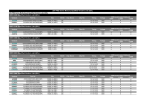
Table. 5-1 SATA Mode setting guide
System BIOS Main Menu
Configuration
SATA Configuration
SATA Mode Selection …….………… [Press enter]
SATA Mode…… [IDE/AHCI /RAID Mode]
CFEX support
The J40 (CF 50pin socket) supports CFEX. (Has SATA signal).
mSATA device support
The J28 (Mini-PCIe slot) has SATA signal can support mSATA device.
WADE-8022 User’s Manual
5-2
Troubleshooting
5.2
BIOS Setting
It is assumed that users have correctly adopted modules and connected all the
devices cables required before turning on ATX power. 204-pin DDR3 SO-DIMM
Memory, keyboard, mouse, SATA hard disk, DVI-I connector, device power cables,
ATX accessories are good examples that deserve attention. With no assurance of
properly and correctly accommodating these modules and devices, it is very possible
to encounter system failures that result in malfunction of any device.
To make sure that you have a successful start with WADE-8022, it is recommended,
when going with the boot-up sequence, to hit “Del” or “Esc” key and enter the BIOS
setup menu to tune up a stable BIOS configuration so that you can wake up your
system far well.
Loading the default optimal setting
When prompted with the main setup menu, please scroll down to “Restore
Defaults”, press “Enter” and select “Yes” to load in default optimal BIOS setup. This
will force your BIOS setting back to the initial factory configuration. It is
recommended to do this so you can be sure the system is running with the BIOS
setting that Portwell has highly endorsed. As a matter of fact, users can load the
default BIOS setting any time when system appears to be unstable in boot up
sequence.
Improper Disable Operation
There are too many occasions where users disable a certain device/feature in one
application through BIOS setting. These variables may not be set back to the original
values when needed. These devices/features will certainly fail to be detected.
When the above conditions happen, it is strongly recommended to check the BIOS
settings. Make sure certain items are set as they should be. These include the Serial
Port1/ Serial Port 2 ports, USB ports, external cache, on-board VGA and Ethernet.
It is also very common that users would like to disable a certain device/port to
release IRQ resource. A few good examples are
Disable Serial Port1 to release IRQ #4
Disable Serial Port2 to release IRQ #3
Etc…
A quick review of the basic IRQ mapping is given below for your reference.
It is then very easy to find out which IRQ resource is ready for additional peripherals.
If IRQ resource is not enough, please disable some devices listed above to release
further IRQ numbers.
WADE-8022 User’s Manual
5-3
Troubleshooting
5.3
FAQ
Information & Support
Question: I forget my password of system BIOS, what am I supposed to do?
Answer: You can simply short 2-3 pins on J20 to clean your password.
Question: How to update the BIOS file of the WADE-8022?
Answer:
1. Please visit web site of the Portwell download center as below hyperlink
and register an account. (The E-Mail box should be an existing
Company email address that you check regularly.)
http://www.portwell.com.tw/member/newmember.php
2. Input your User name and password to log in the download center.
3. Select the “Search download” to input the keyword “WADE-8022”.
4. Find the “BIOS “page to download the ROM file and flash utility.
5. Execute the zip file to root of the bootable USB pen drive which can
boot to DOS mode.
6. Insert your bootable USB pen drive in WADE-8022 board and power-on.
7. Boot to DOS mode then input the “Update” command to start to update
BIOS process.
8. Switch “Off” the Power Supply when you finished the update process.
9. Wait 5 seconds then switch “ON” the Power Supply then press the “Del”
or “Esc” key to BIOS to select “Load Setup Defaults” and then select “Exit
Saving Changes” option.
Note:
Please visit our Download Center to get the Catalog, User manual, BIOS, and driver
files.
http://www.portwell.com.tw/support/download_center.php
If you have other additional technical information or request which is not covered in
this manual, please fill in the technical request form as below hyperlink.
http://www.portwell.com.tw/support/problem_report.php
We will do our best to provide a suggestion or solution for you.
WADE-8022 User’s Manual
5-4
Troubleshooting
System Memory Address Map
Each On-board device in the system is assigned a set of memory addresses, which
also can be identical of the device. The following table lists the system memory
address used for your reference.
Memory Area
0000 – 003F
0040 – 004F
0050 – 006F
0070 – 0E2E
0E2F - 0F6B
0F6C – 9D7F
First Meg
Size
Description
1K
Interrupt Area
0.3K
BIOS Data Area
0.5K
System Data
54K
DOS
5K
Program Area
【Available】
568K
-- Conventional memory end at 630K --
9D80 – 9EFF
9F00 – 9FFF
A000 - AFFF
B000 – B7FF
B800 - BFFF
C000 - CEBF
CEC0 - EFFF
F000 - FFFF
6K
4K
64K
32K
32K
59K
133K
64K
Extended BIOS Area
Unused
VGA Graphics
Unused
VGA Text
Video ROM
Unused
System ROM
HMA
64K
First 64K Extended
WADE-8022 User’s Manual
5-5
Troubleshooting
Interrupt Request Lines (IRQ)
Peripheral devices can use interrupt request lines to notify CPU for the service
required. The following table shows the IRQ used by the devices on board.
Interrupt Request Lines IRQ
Current Use
IRQ#
IRQ 0
IRQ 1
IRQ 2
IRQ 3
IRQ 4
IRQ 5
IRQ 6
IRQ 7
IRQ 8
IRQ 9
IRQ 10
IRQ 11
IRQ 12
IRQ 13
IRQ 14
IRQ 15
System ROM
System ROM
【Unassigned】
System ROM
System ROM
【Unassigned】
System ROM
【Unassigned】
System ROM
【Unassigned】
Video ROM
【Unassigned】
System ROM
System ROM
System ROM
【Unassigned】
WADE-8022 User’s Manual
Default Use
System Timer
Keyboard Event
Usable IRQ
COM2
COM1
Usable IRQ
Diskette Event
Usable IRQ
Real-Time Clock
Usable IRQ
Usable IRQ
Usable IRQ
IBM Mouse Event
Coprocessor Error
Hard Disk Event
Usable IRQ
5-6