1
WADE-8079
Mini-ITX Board
User's Manual
Version 1.1
Copyright © Portwell, Inc., 2014. All rights reserved.
All other brand names are registered trademarks of their respective owners.
Preface
Table of Contents
How to Use This Manual
Chapter 1 System Overview.......................................................................................................1-1
1.1 Introduction ....................................................................................................... 1-1
1.2 Check List........................................................................................................... 1-1
1.3 Product Specification........................................................................................ 1-2
1.3.1 Mechanical Drawing................................................................................ 1-4
1.4 System Architecture.......................................................................................... 1-6
Chapter 2 Hardware Configuration ...........................................................................................2-1
2.1 Jumper Allocation ............................................................................................. 2-2
2.2 Connector Allocation........................................................................................ 2-4
Chapter 3 System Installation....................................................................................................3-1
3.1 Intel® Valleyview CPU .................................................................................... 3-1
3.2 Main Memory .................................................................................................... 3-1
3.3 Installing the Single Board Computer............................................................ 3-1
3.3.1 Chipset Component Driver .................................................................... 3-2
3.3.2 Intel® HD Graphics 4600 ........................................................................ 3-2
3.3.3 Intel LAN I210IT Gigabit Ethernet Controller ..................................... 3-2
3.3.4 Realtek ALC892 HD Audio Controller ................................................. 3-2
3.4 Clear CMOS Operation .................................................................................... 3-2
3.5 WDT Function ................................................................................................... 3-3
3.6 GPIO.................................................................................................................... 3-5
Chapter 4 BIOS Setup Information............................................................................................4-1
4.1 Entering Setup - Launch System Setup.......................................................... 4-1
4.2 Main .................................................................................................................... 4-2
4.3 Configuration .................................................................................................... 4-5
4.4 Others................................................................................................................ 4-18
4.5 Securit ............................................................................................................... 4-21
4.6 Boot ................................................................................................................... 4-22
4.7 Exit..................................................................................................................... 4-23
Chapter 5 Troubleshooting ........................................................................................................5-1
5.1 Hardware Quick Installation........................................................................... 5-1
5.2 BIOS Setting ....................................................................................................... 5-2
5.3 Q&A .................................................................................................................... 5-2
Preface
How to Use This Manual
The manual describes how to configure your WADE-8079 system board to meet
various operating requirements. It is divided into five chapters, with each chapter
addressing a basic concept and operation of Single Host Board.
Chapter 1: System Overview. Presents what you have in the box and give you an
overview of the product specifications and basic system architecture for this series
model of single host board.
Chapter 2: Hardware Configuration. Show the definitions and locations of Jumpers
and Connectors that you can easily configure your system.
Chapter 3: System Installation. Describes how to properly mount the CPU, main
memory and Compact Flash to get a safe installation and provides a programming
guide of Watch Dog Timer function.
Chapter 4: BIOS Setup Information. Specifies the meaning of each setup
parameters, how to get advanced BIOS performance and update new BIOS. In
addition, POST checkpoint list will give users some guidelines of trouble-shooting.
Chapter 5: Troubleshooting. Provide various of useful tips to quickly get
WADE-8079 running with success. As basic hardware installation has been addressed
in Chapter 3, this chapter will basically focus on system integration issues, in terms of
backplane setup, BIOS setting, and OS diagnostics.
The content of this manual is subject to change without prior notice. These changes
will be incorporated in new editions of the document. The vendor may make
supplement or change in the products described in this document at any time.
System Overview
Chapter 1
System Overview
1.1
Introduction
Powell Inc., a world-leading innovator in the Industrial PC (IPC) market and a
member of the Intel® Communications Alliance, has launched its new
WADE-8079 series in response to market demand for a simplified embedded
system board (ESB)that combines a smaller footprint, lower power consumption,
robust computing power and with longevity support.
Built with Intel’s latest chipset, WADE-8079 series take advantage of the Intel®
Atom™ Valleyview E38XX series and Intel® Celeron® J1900 processors.
WADE-8079 has lots of features, also features Two SATA connectors (SATA
3Gb/s) storage specification(Switch with mini-PCIe slot) , Two DDR3 SO-DIMM
memory slot for DDR3L non-ECC SDRAM up to 8GB, support total 5 USB ports
(1x USB3.0 and 2x USB2.0 on REAR I/O, 2x USB2.0 on board header), VGA / DVI
/ DP / LVDS display ,Dual Gigabit Ethernet, and one PCIe x1 slot .
WADE-8079’s ability to drive two displays simultaneously makes them
particularly suitable for lottery and gaming applications. They are also ideal for
applications such as point-of-sale (POS), digital signage, kiosks, Panel PC
1.2
Check List
The WADE-8079 package should cover the following basic items
One WADE-8079 Mini-ITX Main Board
One SATA Cable
One I/O Shield bracket
One Installation Resources CD-Title
If any of these items is damaged or missing, please contact your vendor and keep
all packing materials for future replacement and maintenance.
WADE-8079 User’s Manual
1-1
System Overview
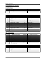
1.3
Product Specification
Main Processor
-Intel® Atom™ Valleyview E38XX series processor
-Intel® Celeron® J1900 processor.
System BIOS
Phoenix BIOS
Main Memory
Two 204 - pin DDR3 SODIMM socket support DDR3L up to 8GB 1066/1333
MHz non-ECC memory
- E3845 / E3827 /J1900 support 1333MHz memory
- E3826 / E3825 / E3815 support 1066MHz memory
Expansion Interface
One PCIex1 slot
SATA Interface
Two SATA ports(SATA 3Gb), Switch with full size mini-PCIe slot
Serial Port
Support three RS232 / one RS232/422/485
USB Interface
Support five USB (Universal Serial Bus) ports, one USB3.0 and two USB2.0 on
rear I/O and two USB2.0 on board header for internal devices
Audio Interface
Line in / Line out / Mic in on board header
Real Time Clock/Calendar (RTC)
Support Y2K Real Time Clock/Calendar
Watch Dog Timer
- Support WDT function through software programming for enable/disable
and interval setting
- General system reset
On-board Ethernet LAN
One Gigabit Ethernet (10/100/1000 Mbits/sec) LAN ports
High Drive GPIO
One pin-header for 8 bit GPIO
System Monitoring Feature
Monitor system temperature and major power sources.
Outline Dimension (L x W)
170mm(6.69’’) x 170mm(6.69’’)
Power Requirements
WADE-8079 User’s Manual
1-2
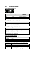
System Overview
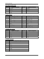
Configuration
CPU Type
SBC BIOS
Memory
VGA Card
VGA Driver
LAN Card
LAN Driver
LAN Card #2
LAN Driver #2
Audio Card
Audio Driver
Chipset Driver
SATA HDD
DVDROM
Power Supply
Intel® Atom™ CPU E3845 @1.9GHz L2:2048K
40411T00
WARIS DDR3L SO-DIMM 1333 1.35V 4GB*2(hynix H5TC2G83EFR)
Onboard Intel® Atom™ Processor E3800 Series/Intel® Celeron®
Intel® Atom™ Processor E3800 Series/Intel® Celeron® Processor
Onboard Intel® I210 Gigabit Network
Intel® I210 Gigabit Network Version:12.7.28.0
Onboard Intel® I210 Gigabit Network#2
Intel® I210 Gigabit Network#2 Version:12.7.28.0
Onboard Realtek ALC892 High Definition Audio
Realtek ALC892 High Definition Audio Version:6.0.1.7083
Intel® Chipset Device Software Version:10.0
WD WD1002FAEX 1TB
LITEON iHAS324 DVD-ROM
Seasonic SSA-0651-1 DC12V
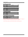
Operating Temperature
0 °C ~ 60 °C
Storage temperature
-20 ~ 80 °C
Relative Humidity
0% ~ 90%, non-condensing
WADE-8079 User’s Manual
1-3
System Overview
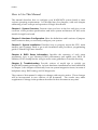
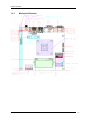
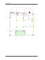
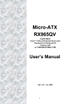
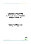
1.3.1
Mechanical Drawing
WADE-8079 User’s Manual
1-4
System Overview
WADE-8079 User’s Manual
1-5
System Overview
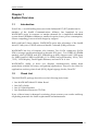
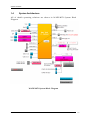
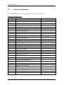
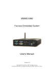
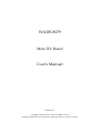
1.4
System Architecture
All of details operating relations are shown in WADE-8079 System Block
Diagram.
WADE-8079 System Block Diagram
WADE-8079 User’s Manual
1-6
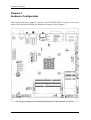
Hardware Configuration
Chapter 2
Hardware Configuration
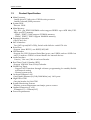
This chapter indicates jumpers’, headers’ and CONNECTORs’ locations. Users may
find useful information related to hardware settings in this chapter.
The jumper settings are schematically depicted in this manual as follows:
WADE-8079 User’s Manual
2-1
Hardware Configuration
2.1
Jumper Allocation
SW1: BIOS recover Switch
PIN NO.
1-4
Function
2-3
OFF
OFF
Normal Operation
ON
OFF
AT Mode
OFF
ON
BIOS recover
JP1: LVDS Channel Link Pin Header
JP1
1-2 Short
1-2 Open
Function
Dual Link LVDS
Single Link LVDS
JP2: LVDS Backlight Enable Pin Header
JP2
1-3,2-4 Short
1-3,4-6 Short
3-5,2-4 Short
3-5,4-6 Short
Function
5V, Active High(Normal)
12V, Active High
5V, Active Low
12V, Active Low
JP3: LVDS VDD Pin Header
JP3
1-3 Short
3-5 Short
3-4 Short
Function
3.3V
5V
+12V
JP10: LVDS color depth and data mapping Pin Header
JP10
Function
2-4 Short 8-bit LVDS, VESA mapping
1-3 Short 6-bit LVDS, both VESA and JEIDA mapping
1-3,2-4 Short 8-bit LVDS, JEIDA mapping
WADE-8079 User’s Manual
2-2
Hardware Configuration
JP6: CMOS Clear Pin Header
JP6
1-2 Short
2-3 Short
Function
Normal Operation
Clear CMOS Contents
JP7: SATA / mSATA Selection Pin Header (J16 / J25 Selection)
JP7
1-2 Short
2-3 Short
Function
mSATA
SATA
JP8: GPIO VDD Pin Header
JP8
1-2 Short
2-3 Short
Function
5V
3.3V
JP9: Watchdog Timer Function Pin Header
JP9
1-2 Short
1-2 Open
Function
Normal Operation
WDT Disable
*Note1: Dual display mode switch for LVDS and DP. When the user change the
display mode on BIOS item, the system need to be full reset again.
*Note2: COM1 could be set to RS-232, RS-422, RS-485 via BIOS Setup Item.
WADE-8079 User’s Manual
2-3
Hardware Configuration
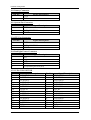
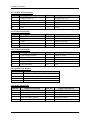
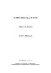
2.2
Connector Allocation
I/O peripheral devices are connected to the interface connectors.
Connector Function List
Connector
J3
J4
Function
12/24V DC Jack
DVI-D+VGA Connector
J5
J6
COM1 & COM2 Connector
DP Connector
J7
J8
J9
J10
USB2.0 X2 Connector
USB3.0 Connector
LAN X2 Connector
Battery Connector
J11
System Fan Connector
J12
PCI-E X1 Slot
J13
J14
J15
J16
CPU Fan Connector
Backlight Power Connector
LVDS Connector
SATA Connector
J17
J18
J19
J20
J21
J22
USB2.0 X2 Pin Header
COM4 Pin Header
SATA Connector
COM3 Pin Header
Speaker Pin Header
Audio Pin Header
J23
SM Bus Pin Header
J24
Mini-PCI-E Connector
J25
mSATA Connector
J27
DDR3L SODIMM0 Socket
J28
8-bit GPIO Pin Header
J29
KB/MS PS2 Pin Header
J31
WDT LED Pin Header
J32
TPM Connector
J33
Front Panel Pin Header
J37
DDR3L SODIMM1 Socket
J38,J40
SATA Power Connector
WADE-8079 User’s Manual
Remark
2-4
Hardware Configuration
Pin Assignments of Connectors
J3: 12/24V DC Jack
PIN No.
1
3
Signal Description
+12/24V
Ground
PIN No.
2
Signal Description
Ground
PIN No.
2
4
6
8
10
12
14
16
18
20
22
24
CG2
Signal Description
TMDS Data 2+
TMDS Data 4DDC clock
NC
TMDS Data 1+
TMDS Data 3+5V
Hot Plug Detect
TMDS Data 0+
TMDS Data 5TMDS Clock Shield
TMDS ClockCG2
PIN No.
2
4
6
8
10
12
14
16
Signal Description
Green
NC
RGND
BGND
SGND
SDA
V Sync
PIN No.
2
4
6
8
Signal Description
RXD#1/485D/422T+
DTR#1/422RDSR#1
CTS#1
J4A: DVI-D Connector
PIN No.
1
3
5
7
9
11
13
15
17
19
21
23
CG1
Signal Description
TMDS Data 2TMDS Data 2/4 Shield
TMDS Data 4+
DDC data
TMDS Data 1TMDS Data 1/3 Shield
TMDS Data 3+
GND
TMDS Data 0TMDS Data 0/5 Shield
TMDS Data 5+
TMDS Clock+
CG1
J4B: VGA Connector
PIN No.
Signal Description
1
Red
3
Blue
5
GND
7
GGND
9
KEY(+5V)
11
NC
13
H Sync
15
SCL
J5A: COM1 CONNECTOR
PIN No.
1
3
5
7
9
Signal Description
DCD#1/485D/422TTXD#1/422R+
GND
RTS#1
RI#1
WADE-8079 User’s Manual
2-5
Hardware Configuration
J5B: COM2 CONNECTOR
PIN No.
1
3
5
7
9
Signal Description
DCD#2
TXD#2
GND
RTS#2
RI#2
PIN No.
2
4
6
8
Signal Description
RXD#2
DTR#2
DSR#2
CTS#2
PIN No.
2
4
6
8
10
12
14
16
18
20
Signal Description
GND
ML_Lane 1 (p)
ML_Lane 1 (n)
GND
ML_Lane 3 (p)
ML_Lane 3 (n)
GND
GND
Hot Plug Detect
DP_PWR(+3.3V)
PIN No.
B1
B2
B3
B4
CG2
CG4
Signal Description
+5V
DD+
GND
GND
GND
J6: DP Connector
PIN No.
1
3
5
7
9
11
13
15
17
19
Signal Description
ML_Lane 0 (p)
ML_Lane 0 (n)
GND
ML_Lane 2 (p)
ML_Lane 2 (n)
GND
GND
AUX CH (p)
AUX CH (n)
GND
J7: USB2.0 X2 Connector
PIN No.
A1
A2
A3
A4
CG1
CG3
Signal Description
+5V
DD+
GND
GND
GND
J8: USB3.0 Connector
PIN No.
1
2
3
4
5
6
7
8
9
Signal Description
+5V
DD+
GND
SSRXSSRX+
GND
SSRTSSRT+
WADE-8079 User’s Manual
2-6
Hardware Configuration
J10: Battery Connector
Pin No.
1
2
Signal Description
+3.3V
GND
J11: System Fan Connector
Pin No.
Signal Description
1
GND
2
3
PWM_CONTROL
SENSE
J13: CPU Fan Connector
Pin No.
Signal Description
1
GND
2
3
PWM_CONTROL
SENSE
J14: Backlight Power Connector
Pin No.
1
2
3
4
5
Signal Description
+5V
Brightness control
+12V
GND
+5V(Enable pin from JP2)
J15: LVDS CONNECTOR
Pin No.
2
4
6
8
10
12
14
16
18
20
22
24
26
28
30
Signal Description
VDD_LVDS
LCD1DO0LCD1DO1LCD1DO2LCD1DO3LCD1CLKLDATA1
GND
LCD2DO0LCD2DO1LCD2DO2LCD2DO3LCD2CLKNC
GND
WADE-8079 User’s Manual
Pin No.
1
3
5
7
9
11
13
15
17
19
21
23
25
27
29
Signal Description
VDD_LVDS
LCD1DO0+
LCD1DO1+
LCD1DO2+
LCD1DO3+
LCD1CLK+
LCLK1
GND
LCD2DO0+
LCD2DO1+
LCD2DO2+
LCD2DO3+
LCD2CLK+
NC
GND
2-7
Hardware Configuration
J17: USB2.0 X2 Pin Header
PIN No.
1
3
5
7
9
Signal Description
USB power (5V)
USB DATA AUSB DATA A+
GND
KEY
PIN No.
2
4
6
8
10
Signal Description
USB power (5V)
USB DATA AUSB DATA A+
GND
KEY
PIN No.
2
4
6
8
10
Signal Description
Receive Data
Data Terminal Ready
Data Set Ready
Clear To Send
NC
PIN No.
2
4
6
8
10
Signal Description
Receive Data
Data Terminal Ready
Data Set Ready
Clear To Send
NC
J18: COM4 Pin Header
PIN No.
1
3
5
7
9
Signal Description
Data Carrier Detect
Transmit Data
GND
Request To Send
Ring Indicator
J20: COM3 Pin Header
PIN No.
1
3
5
7
9
Signal Description
Data Carrier Detect
Transmit Data
GND
Request To Send
Ring Indicator
J21: Speaker Pin Header
Pin No.
Signal Description
1
AMP_R+
2
3
4
AMP_RAMP_LAMP_L+
J22: Audio Pin Header
PIN No.
1
3
5
7
9
Signal Description
MIC with Reference Voltage
Line-in Left Channel
Line-in Right Channel
Line-out Left Channel
Line-out Right Channel
WADE-8079 User’s Manual
PIN No.
2
4
6
8
10
Signal Description
Analog Ground
Analog Ground
Analog Ground
Analog Ground
KEY
2-8
Hardware Configuration
J23: SM Bus Pin Header
Pin No.
1
2
3
4
5
Signal Description
SM Bus Clock
X
GND
SM Bus Data
+5V
J28: 8-bit GPIO Pin Header
PIN No.
1
3
5
7
9
Signal Description
GPIO00
GPIO01
GPIO02
GPIO03
GND
PIN No.
2
4
6
8
10
Signal Description
GPIO04
GPIO05
GPIO06
GPIO07
5VSB
PIN No.
2
4
6
8
10
Signal Description
KB_DATA
NC
GND
+5V
KB_CLK
J29: KB/MS PS2 Pin Header
PIN No.
1
3
5
7
9
Signal Description
MS_DATA
NC
GND
+5V
MS_CLK
J31: WDT LED Pin Header
PIN No.
1
2
Signal Description
+5V
WDT#
J32: TPM Connector
PIN No.
1
3
5
7
9
11
13
15
17
19
Signal Description
TPM_CLK
LFRAME#
TPM_RESET#
LAD3
3.3V
LAD0
SMB_CLK
3VSB
GND
LPCPD#
WADE-8079 User’s Manual
PIN No.
2
4
6
8
10
12
14
16
18
20
Signal Description
GND
NC
5V
LAD2
LAD1
GND
SMB_DATA
SERIRQ
NC
NC
2-9
Hardware Configuration
J33: Front Panel Pin Header
PIN No.
1
3
5
7
9
11
13
15
Signal Description
+5V(330 ohm)
Power LED
+3.3V(LAN1) (330 ohm)
LAN1_LED_LINK#/ACT#
LAN2_LED_LINK#/ACT#
+3.3V(LAN2) (330 ohm)
+5V/+3.3V(330 ohm)
HDD LED#
PIN No.
2
4
6
8
10
12
14
16
Signal Description
+5V
GND
KEY
BUZZER
GND
Power Switch
Reset Switch
GND
J38,J40: SATA Power Connector
Pin No.
1
2
3
4
Signal Description
+12V
GND
GND
+5V
WADE-8079 User’s Manual
2-10
System Installation
Chapter 3
System Installation
This chapter provides you with instructions to set up your system. The additional
information is enclosed to help you set up onboard PCI device and handle Watch Dog
Timer (WDT) and operation of GPIO in software programming.
3.1
Intel® Valleyview CPU
Intel® E3800 family CPU
3.2
Main Memory
WADE-8079 provides 1 x 204-pin SO-DIMM sockets which supports 1333 MHz
DDR3L-SDRAM (1.35V) memory as main memory, non-ECC (non-Error Checking
and Correcting). The maximum memory can be up to 8GB. Memory clock and related
settings can be detected by BIOS via SPD interface.
Watch out the contact and lock integrity of memory module with socket, it will
impact on the system reliability. Follow normal procedures to install memory module
into memory socket. Before locking, make sure that all modules have been fully
inserted into the card slots.
3.3
Installing the Single Board Computer
To install your WADE-8079 into standard chassis or proprietary environment, please
perform the following:
Step 1 : Check all jumpers setting on proper position
Step 2 : Install and configure CPU and memory module on right position
Step 3 : Place WADE-8079 into the dedicated position in the system
Step 4 : Attach cables to existing peripheral devices and secure it
WARNING
Please ensure that mother board is properly inserted and fixed by mechanism.
Note:
Please refer to section 3.3.1 to 3.3.4 to install INF, Graphic, LAN and Audio drivers.
WADE-8079 User’s Manual
3-1
System Installation
3.3.1
Chipset Component Driver
WADE-8079 uses state-of-art Intel® BayTrail-I chipset. It’s a new chipset that some
old operating systems might not be able to recognize. To overcome this compatibility
issue, for Windows Operating Systems such as Windows 8, please install its INF
before any of other Drivers are installed. You can find very easily this chipset
component driver in NANO-6060 CD-title
3.3.2
Intel® HD Graphics 4600
WADE-8079 has integrated Intel® HD Graphics 4600 which supports DX-11,
OpenGL-4.0. It is the most advanced design to gain an outstanding graphic
performance. WADE-8079 supports VGA, DVI-D, DP and dual channel 24 bit LVDS.
This combination makes WADE-8079 an excellent piece of multimedia hardware.
Drivers Support
Please find the Graphic driver in the WADE-8079 CD-title. The driver supports
Windows 8.
3.3.3
Intel LAN I210IT Gigabit Ethernet Controller
Dual Intel I210IT Gigabit Ethernet controller and 2x RJ45 connectors on rear I/O.
Drivers Support
Please find Intel I210IT LAN driver in /Ethernet directory of WADE-8079 CD-title.
The driver supports Windows 8.
3.3.4
Realtek ALC892 HD Audio Controller
Please find Realtek ALC892 HD Audio driver form WADE-8079 CD-title. The driver
supports Windows 8.
3.4
Clear CMOS Operation
The following table indicates how to enable/disable Clear CMOS Function hardware
circuit by putting jumper in the board.
JP6: CMOS Clear Pin Header
JP6
1-2 Short
2-3 Short
Function
Normal Operation
Clear CMOS Contents
WADE-8079 User’s Manual
3-2
System Installation
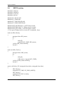
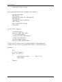
3.5
WDT Function
#include <stdio.h>
#include <stdlib.h>
#include <conio.h>
#include <dos.h>
#define EC_DATA 0x62
#define EC_CMD 0x66
#define EC_CMD_READ 0x80
#define EC_CMD_WRITE 0x81
#define WDT_MODE 0x06 // WDT Select mode.
#define WDT_MIN 0x07 // Minute mode counter
#define WDT_SEC 0x08 // Second mode counter
// Use port 62 and port 66 to access EC command / data.
static int IBF_Check()
{
unsigned char IBF_status;
do
{
delay(2);
outportb (EC_CMD, IBF_status);
} while (IBF_status & 0x02);
return 1;
}
static int OBF_Check ()
{
unsigned char OBF_status;
do
{
delay(2);
OBF_status = inportb (EC_CMD);
} while (!(OBF_status & 0x01));
return 1;
}
static void Write_EC (unsigned char index, unsigned char data)
{
IBF_Check ();
outportb (EC_CMD, EC_CMD_WRITE);
IBF_Check ();
outportb (EC_DATA, index);
IBF_Check ();
WADE-8079 User’s Manual
3-3
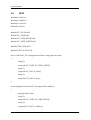
System Installation
outportb (EC_DATA, data);
}
static unsigned char Read_EC (unsigned char address)
{
unsigned char data;
IBF_Check ();
outportb (EC_CMD, EC_CMD_READ);
IBF_Check ();
outportb (EC_DATA, address);
OBF_Check();
data = inportb (EC_DATA);
return data;
}
void EC_WDT_Trigger ()
{
/* WDT Counter */
Write_EC (WDT_SEC, 0x05);
/* if use minute mode */
/* Write_EC (WDT_MIN, 0x05); */
/* 0x01 is second mode */
/* 0x03 is minute mode */
Write_EC (WDT_MODE, 0x01);
}
//Write_EC ((b->wdt.ec.count_m_addr & 0xFF), b->wdt.ec.timeout);
//Write_EC ((b->wdt.ec.cfg_addr & 0xFF), 0x03); //WDTCFG[1:0]=11
int main ()
{
int i;
EC_WDT_Trigger ();
for (i = 0; i < 5; i++)
{
printf ("Reset counter ...................%d\n", 5 - i);
delay (1000);
}
return 0;
}
WADE-8079 User’s Manual
3-4
System Installation
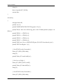
3.6
GPIO
#include <stdio.h>
#include <stdlib.h>
#include <conio.h>
#include <dos.h>
#define EC_DATA 0x62
#define EC_CMD 0x66
#define EC_CMD_READ 0x80
#define EC_CMD_WRITE 0x81
#define GPIO_DIR 0x2B
#define GPIO_DATA 0x2C
static void Write_EC (unsigned char index, unsigned char data)
{
sleep(1);
outportb (EC_CMD, EC_CMD_WRITE);
sleep(1);
outportb (EC_DATA, index);
sleep(1);
outportb (EC_DATA, data);
}
static unsigned char Read_EC (unsigned char address)
{
unsigned char data;
sleep(1);
outportb (EC_CMD, EC_CMD_READ);
sleep(1);
outportb (EC_DATA, address);
WADE-8079 User’s Manual
3-5
System Installation
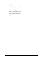
sleep(1);
data = inportb (EC_DATA);
return data;
}
int main ()
{
unsigned char d2;
printf("\n\n");
printf("WADE-8079 GPIO TEST Program v1.0\n");
printf("Please short the following pins with 2.54mm-pitched jumper on
JP8\n");
printf("GPIO1 ---- GPIO2\n");
printf("GPIO3 ---- GPIO4\n");
printf("GPIO5 ---- GPIO6\n");
printf("GPIO7 ---- GPIO8\n");
printf("GND xxxx Vcc <==PWR/GND pins, DO NOT short them!\n\n");
printf("LED Test Begins...\n");
/* Set GPIO Port In/Out mode */
Write_EC (GPIO_DIR, 0x00);
sleep (2);
printf("Write_EC mode 0x00\n");
/* Set Low or High */
Write_EC (GPIO_DATA, 0xFF);
printf("Write_EC data 0xFF\n");
sleep (2);
/* Set GPIO Port In/Out mode */
Write_EC (GPIO_DIR, 0x00);
WADE-8079 User’s Manual
3-6
System Installation
sleep (2);
printf("Write_EC mode 0x00\n");
/* Set Low or High */
Write_EC (GPIO_DATA, 0x00);
printf("Write_EC data 0x00\n");
sleep (2);
return 0;
}
WADE-8079 User’s Manual
3-7
BIOS Setup Information
Chapter 4
BIOS Setup Information
WADE-8079 is equipped with the Phoenix BIOS stored in Flash ROM. These BIOS has
a built-in Setup program that allows users to modify the basic system configuration
easily. This type of information is stored in CMOS RAM so that it is retained during
power-off periods. When system is turned on, WADE-8079 communicates with
peripheral devices and checks its hardware resources against the configuration
information stored in the CMOS memory. If any error is detected, or the CMOS
parameters need to be initially defined, the diagnostic program will prompt the user
to enter the SETUP program. Some errors are significant enough to abort the start up.
.
4.1
Entering Setup - Launch System Setup
Power on the computer and the system will start POST (Power On Self Test) process.
When the message below appears on the screen, press <F2> key will enter BIOS setup
screen.
Press <F2> to enter SETUP
If the message disappears before responding and still wish to enter Setup, please
restart the system by turning it OFF and On or pressing the RESET button. It can be
also restarted by pressing <Ctrl>, <Alt>, and <Delete> keys on keyboard
simultaneously.
Press <F1> to Run General Help or Resume
The BIOS setup program provides a General Help screen. The menu can be easily
called up from any menu by pressing <F1>. The Help screen lists all the possible keys
to use and the selections for the highlighted item. Press <Esc> to exit the Help screen.
WADE-8079 User’s Manual
4-1
BIOS Setup Information
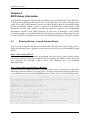
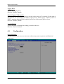
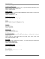
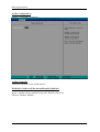
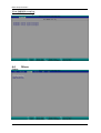
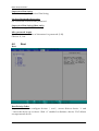
4.2
Main
Main
Use this menu for basic system configurations, such as time, date etc.
System Date
View or set system date
The date format is <Day>, <Month> <Date> <Year>. Use [+] or [-] to configure
system Date.
System Time
View or set system time
The time format is <Hour> <Minute> <Second>. Use [+] or [-] to configure system
Time.
WADE-8079 User’s Manual
4-2
BIOS Setup Information
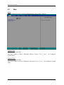
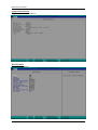
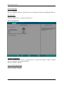
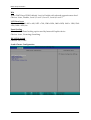
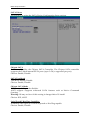
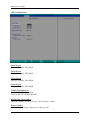
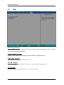
System Information
Display System Information.
Boot Features
Select Boot features.
WADE-8079 User’s Manual
4-3
BIOS Setup Information
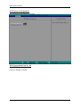
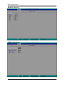
NumLock:
Selects Power-on state for NumLock
Choices: On, Off.
Timeout
Number of seconds that P.O.S.T will wait for the user input before booting
Choices: 0-99 seconds.
CSM Support
Compatibility Support Module that provide backward compatibility services for
legacy BIOS services, like int10/int13, dependent OS.
Quick Boot
Enable/Disable quick boot
Choices: Disable, Enable.
Diagnostic Splash Screen
If you select ‘Enabled’ the diagnostic splash screen always displays during boot. If
you select ‘Disabled’ the diagnostic splash screen does not displays unless you press
HOTKEY during boot
Choices: Disable, Enable.
Diagnostic Summary Screen
Display the Diagnostic summary screen during boot
Choices: Disable, Enable.
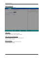
BIOS Level USB
Enable/Disable all BIOS support for USB in order to reduce boot time. Note that this
will prevent using a USB keyboard in setup or a USB biometric scanner such as a
finger print reader to control access to setup, but does not prevent the operating
system from supporting such hardware
Choices: Disable, Enable.
Console Redirection
Enable/Disable Universal Console Redirection
Choices: Disable, Enable.
Allow Hotkey in S4 Resume
Enable hotkey detection when system resuming from Hibernate state
Choices: Disable, Enable.
UEFI Boot
Enable the UEFI boot.
Choices: Disable, Enable.
WADE-8079 User’s Manual
4-4
BIOS Setup Information
Legacy Boot
Enable the Legacy boot
Choices: Disable, Enable.
Boot in Legacy Video mode
Enable to force the display adapter to switch video mode to Text mode 3 at the end of
BIOS POST for non-UEFI boot mode (Legacy boot). Some legacy software, such as
DUET, requires that the BIOS explicitly enter text video mode prior to boot.
Choices: Disable, Enable.
Load OPROM
Load OPROMs or demand according to the boot device.
Choices: All, On demand.
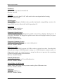
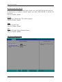
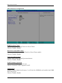
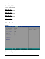
4.3
Configuration
Setup Warning:
Setting items on this screen to incorrect values may cause system to malfunction!
Advanced
WADE-8079 User’s Manual
4-5
BIOS Setup Information
Select Language
Select Language
Choices: English, Japanese, French, Korean, Traditional Chinese, Simplified Chinese.
OS Selection
OS Selection
Choices: Windows 8.x, Android, Windows 7.
CPU Configuration
Execute Disabled Bit
Execute Disabled Bit prevent certain classes of malicious buffer overflow attacks
when combined with a supporting OS
Choices: Disable, Enable.
Limit CPUID Maximum
Disabled for Windows XP
Choices: Disable, Enable.
WADE-8079 User’s Manual
4-6
BIOS Setup Information
Bi-directional PROCHOT#
When a processor thermal sensor trips (either core), the PROCHOT# will be driven
If bi-direction is enabled, external agents can drive PROCHOT# to throttle the
processor
Choices: Disable, Enable.
VTX-2
To enable or disable the VTX-2 Mode support
Choices: Disable, Enable.
TM1
Enable/Disable TM1
Choices: Disable, Enable.
DTS
Enabled/Disable Digital Thermal Sensor
Choices: Disable, Enable.
CPU Power Management
System Power Options
WADE-8079 User’s Manual
4-7
BIOS Setup Information
Intel® SpeedStep™
Enable processor performance status (P-Status)
Choices: Disabled, Enabled.
Boot performance mode
Select the performance state that the BIOS will set before OS handoff
Choices: Max Performance, Max Battery.
Intel® Turbo Boot Technology
Enable to automatically allow processor cores to run faster than the base operation
frequency if it’s operating below power, current, and temperature specification limits.
Choices: Disable, Enable.
C-States
Enable/Disable C States
Choices: Disable, Enable.
Uncore Configuration
GOP Driver
Enable GOP Driver will unload VBIOS; Disable it will load VBIOS
Choices: Enable, Disable.
WADE-8079 User’s Manual
4-8
BIOS Setup Information
Integrated Graphic Device
Enable: Enable Integrated Graphics Device (IGD) when selected as the Primary Video
Adapter. Disable: Always disable IGD
Choices: Disable, Enable.
Primary Display
Select which of IGD/PCI Graphics device should be Primary Display. Or select SG for
switchable / Hybrid Gfx.
Choices: Auto, IGD, PCIe, SG.
RC6 (Rander Standby)
Check to enable render standby support
Choices: Enable, Disable.
PAVC
Enable/Disable Protected Audio Video control.
Choices: Disable, LITE Mode, SERPENT Mode.
GTT Size
Select the GTT Size
Choices: 1MB, 2MB.
Aperture Size
Select the Aperture Size
Choices: 128MB, 256MB, 512MB.
DVMT Pre-Allocated
Select DVMT 5.0 Pre-Allocated (Fixed) Graphics Memory sized used by the Internal
Graphic Device
Choices: 32M, 64M, 96M, 128M, 160M, 192M, 224M, 256M, 288M, 320M, 352M,
384M,416M, 448M, 480M, 512M.
IGD Turbo
Select the IGD turbo feature, if auto selected, IGD turbo will only be enabled when
SOC stepping is B0 or above.
Choices: Auto, Enable, Disable.
Spread Spectrum clock
Enable clock chip Spread Spectrum feature
Choices: Disable, Enable.
Force Lid States
For test: Force to set lid status as on or off
Choices: OFF, ON.
WADE-8079 User’s Manual
4-9
BIOS Setup Information
BIA
Auto: GMCH use VBIOS default, Level n: Enable with selected aggressiveness level.
Choices: Auto, Disable, Level 1, Level 2, Level 3, Level 4, Level 5.
LCD Panel type
Choices: 640 x 480, 800 x 600, 1025 x 768, 1280 x1024, 1400 x1050, 1600 x 1200, 1360
x768, 1680 x 1050, etc.
Panel Scaling
Select the LCD Panel scaling option used by Internal Graphic device
Choices: Auto, Centering, Stretching.
DP LVDS Switch
Choices: DP, LVDS.
South Cluster Configuration
WADE-8079 User’s Manual
4-10
BIOS Setup Information
PCI Express Configuration
PCI Express Configuration Settings
PCI Express Root Port #1 - #2
Control PCI Express root port
Choices: Enable, Disable.
WADE-8079 User’s Manual
4-11
BIOS Setup Information
USB Configuration
USB Configuration settings
xHCI Mode
Mode of operation of xHCI controller
Choices: Smart Auto, Auto, Enable, Disable.
xHCI Link Power Management
Enable/Disable xHCI Link Power Management
Choices: Enable, Disable.
EHCI Controller
Control the USB EHCI (USB 2.0) function.
Choices: Enable, Disable.
WADE-8079 User’s Manual
4-12
BIOS Setup Information
Audio Configuration
Audio Configuration Settings
Audio Controller
Control Detection of the Azalia device.
Disabled = Azalia will be unconditionally disabled.
Enabled = Azalia will be unconditionally enabled.
Auto = Azalia will be enabled if present. Disable otherwise
Choices: Disable, Enable.
WADE-8079 User’s Manual
4-13
BIOS Setup Information
SATA Drives
Press<Enter> to select the SATA Device Configuration Setup options.
Chipset SATA
Enables or Disables the Chipset SATA Controller. The Chipset SATA controller
supports the 2 black internal SATA ports (up to 3 Gb/s supported per port).
Choices: Enable, Disable.
SATA Test Mode
Test Mode Enable/Disable
Choices: Enable, Disable.
Chipset SATA Mode
IDE: Compatibility mode disables.
AHCI support: Supports advanced SATA features such as Native Command
Queuing.
Warning: OS may not boot if this setting is changed after OS install.
Choices: IDE, AHCI.
Serial Port 0/1 Hot Plug Capability
If enabled, SATA port 0/1 will be reported as Hot Plug capable.
Choices: Enable, Disable.
WADE-8079 User’s Manual
4-14
BIOS Setup Information
Miscellaneous Configuration
High Precision Timer
Enable or Disable the High Precision Event Timer.
Choices: Disable, Enable.
Boot Time with HPET Timer
Boot time calculation with High Precision Event Timer enable.
Choices: Disable, Enable.
Clock Spread Spectrum
Enable Clock Chip’s Spread Spectrum feature.
Choices: Disable, Enable.
UART Interface Selection
Select which UART interface to use.
Choices: Intermal UART, SuperIO UART.
SMM LOCK
Enable/Disable SMM Lock feature. It will lock the SMRAM and unable load SMM
driver any more.
Choices: Disable, Enable.
WADE-8079 User’s Manual
4-15
BIOS Setup Information
Pci Mmio Size
Pci Mmio Size.
Choices: 2 GB, 1.5 GB, 1.25 GB, 1GB.
NGFF Card Inserted
Set “YES” if NGFF Card is inserted.
Choices: No, Yes.
UHPAM Card Inserted
Set “YES” if UHPAM Card is inserted.
Choices: No, Yes.
Security Configuration
TXE
Choices: Disable, Enable.
TXE HMRFPO
Choices: Disable, Enable.
TXE Firmware Update
Choices: Disable, Enable.
WADE-8079 User’s Manual
4-16
BIOS Setup Information
TXE EOP Message
Choices: Disable, Enable.
TXE Unconfiguration Perform
Choices: No, Yes.
SMBIOS Event Log
Manage SMBIOS Event Log.
Event Log
Enable/Disable Event Log.
Choices: Disable, Enable.
Mark SMBIOS events as read
Mark SMBIOS events as read. Marked SMBIOS events won’t be displayed.
Choices: No, Yes.
Clears SMBIOS events
Clears SMBIOS events.
Choices: No, Yes.
WADE-8079 User’s Manual
4-17
BIOS Setup Information
View SMBIOS event log
View SMBIOS event log
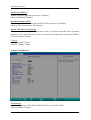
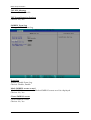
4.4
Others
Others
WADE-8079 User’s Manual
4-18
BIOS Setup Information
SIO Configuration
Serial Port 1
Choices: Disable, 3F8/IRQ4.
Serial Port 2
Choices: Disable, 2F8/IRQ3.
Serial Port 3
Choices: Disable, 3F8/IRQA.
Serial Port 4
Choices: Disable, 2F8/IRQB.
COM1 Configuration
Select COM1 Configuration.
Choices: RS-232, RS-422, RS-485.
Watch Dog Timer Select
Choices: Disable, 15 secs, 30 secs, 1 min, 2 mins, 3 mins.
Power Control
Choices: Former State, Always On, Always Off.
WADE-8079 User’s Manual
4-19
BIOS Setup Information
Hardware Monitor
APM Configuration
WADE-8079 User’s Manual
4-20
BIOS Setup Information
Power On By RTC Alarm
Choices: Disable, Enable.
Wake on LAN1
Choices: Disable, Enable.
Wake on LAN2
Choices: Disable, Enable.
Wake on LAN1
Choices: Disable, Enable.
Wake up by Ring
Choices: Disable, Enable.
4.5
Securit
Security
Set Supervisor Password
Set or clear the Supervisor account’s password.
WADE-8079 User’s Manual
4-21
BIOS Setup Information
Supervisor Hint String
Press Enter to type Supervisor Hint String.
Set User Password (Show only)
Set or clear the User account’ password.
Supervisor Hint String (Show only)
Press Enter to type User Hint String.
Min. password length
Set the minimum number of characters for password (1-20).
Choices: 0, 1.etc
4.6
Boot
Boot
Boot Priority Order
Keys used to view or configure devices: ↑ and ↓ arrows Select a device. ‘+’ and
‘-‘move the device up or down. ‘Shift + 1’ enabled or disables a device. ‘Del’ deletes
an unprotected device.
WADE-8079 User’s Manual
4-22
BIOS Setup Information
4.7
Exit
Exit Saving Changes
Equal to F10, save all changes of all menus, then exit setup configure driver. Finally
resets the system automatically.
Exit Discarding Changes
Equal to ESC, never save changes, then exit setup configure driver.
Load Setup Defaults
Equal to F9. Load standard default values.
Discard Changes
Load the original value of this boot time. Not the default Setup value.
Save Changes
Save all changes of all menus, but do not reset system.
WADE-8079 User’s Manual
4-23
Troubleshooting
Chapter 5
Troubleshooting
This chapter provides a few useful tips to quickly get WADE-8079 running with
success. As basic hardware installation has been addressed in Chapter 2, this chapter
will primarily focus on system integration issues, in terms of BIOS setting, and OS
diagnostics.
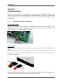
5.1
Hardware Quick Installation
ATX Power Setting
Unlike other Single board computer, WADE-8079 supports a Power adaptor only.
Therefore, there is no other setting that really needs to be set up. However, there is 12
/ 24V DC Jack – J3 on the WADE-8079 board.
12 / 24V DC Jack – J3
Serial ATA
Unlike IDE bus, each Serial ATA channel can only connect to one SATA hard disk at a
time;
The installation of Serial ATA is simpler and easier than IDE, because SATA hard
disk doesn’t require setting up Master and Slave, which can reduce mistake of
hardware installation.
The WADE-8079 can support two SATA interface (SATAII, 3.0 Gb/s) with IDE or
AHCI mode. It has two J16 & J19 SATA ports on the board.
WADE-8079 User’s Manual
5-1
Troubleshooting
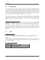
5.2
BIOS Setting
It is assumed that users have correctly adopted modules and connected all the
devices cables required before turning on ATX power. 204-pin DDR3L Memory,
keyboard, mouse, SATA hard disk, VGA connector, power cable of the device, ATX
accessories are good examples that deserve attention. With no assurance of properly
and correctly accommodating these modules and devices, it is very possible to
encounter system failures that result in malfunction of any device.
To make sure that you have a successful start with WADE-8079, it is recommended,
when going with the boot-up sequence, to hit “F2” key and enter the BIOS setup
menu to tune up a stable BIOS configuration so that you can wake up your system far
well.
Loading the default optimal setting
When prompted with the main setup menu, please scroll down to “Load Setup
Defaults”, press “Enter” and select “Yes” to load in default optimal BIOS setup. This
will force your BIOS setting back to the initial factory configuration. It is
recommended to do this so you can be sure the system is running with the BIOS
setting that Portwell has highly endorsed. As a matter of fact, users can load the
default BIOS setting any time when system appears to be unstable in boot up
sequence.
5.3
Q&A
Information & Support
Question: I forget my password of system BIOS, what am I supposed to do?
Answer:
You can switch off your power supply then find the JP6 to set it from 1-2 short to 2-3
short and wait 5 seconds to clean your password then set it back to 1-2 short to switch
on your power supply.
JP6: CMOS Clear Pin Header
JP6
1-2 Short
2-3 Short
Function
Normal Operation
Clear CMOS Contents
WADE-8079 User’s Manual
5-2
Troubleshooting
Question: How to update the BIOS file of the WADE-8079?
Answer:
1. Please visit web site of the Portwell Download Center as below hyperlink
http://www.portwell.com.tw/support/download_center.php
Then you must register an account first.
http://www.portwell.com.tw/member/newmember.php (The E-Mail box should be
an existing Company email address that you check regularly.)
2. Input your User name and password to log in the download center.
3. Select the “Search download” to input the keyword “WADE-8079”.
4. Find the “BIOS“ page to download the ROM file and flash utility.
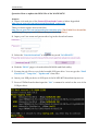
5. Execute the zip file to root of the bootable USB pen drive. You can get the “Shell
Flash 32.efi”, ”temp.bin”, ”Update.nsh” three files.
6. Insert your USB pen drive in USB port of the WADE-8079 board and power-on.
7. Boot to EFI-Shell mode then input the “fs0:” command to switch to the root of the
USB pen drive.
WADE-8079 User’s Manual
5-3
Troubleshooting
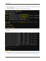
8. Enter the folder you save update image by command [cd “folder name”], in this
case is [cd update]
9. Type the ”update” command to start flash BIOS processes.
10. When it finished all update processes, please reboot your system around 5
seconds.
11.
12. Please press the “F2” key to BIOS setup menu to select “Load Setup Defaults”
and then select “Exit Saving Changes” option to finish all BIOS flash processes.
WADE-8079 User’s Manual
5-4
Troubleshooting
Question: How to install USB 3.0 Windows 7 driver of the WADE-8079?
Answer:
Because of the WADE-8079 is Bay Trail platform, USB 3.0 driver need to use the other
method to install USB 3.0 driver on windows 7, but windows 8 OS doesn’t.
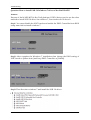
Step1. You must disable the XHCI mode and enable the EHCI Controller from BIOS
setup menu before install windows 7.
Step2. After complete the Windows 7 installation then change the BIOS setting of
XHCI mode to [Smart Auto] and keep EHCI Controller as [Enable].
Step3. Then Boot into windows 7 and install the USB 3.0 driver.
WADE-8079 User’s Manual
5-5
Troubleshooting
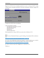
Step4. After USB 3.0 driver installed completely, you have to change the BIOS setting
of XHCI mode to [Enable] and EHCI Controller to [Disable], and then complete the
procedure.
Complete the USB 3.0 driver installation.
Following the above 4 steps, USB 3.0 can work well on Windows 7 OS.
Note:
Please visit our Download Center to get the Catalog, User manual, BIOS, and driver
files.
http://www.portwell.com.tw/support/download_center.php
If you have other additional technical information or request which is not covered in
this manual, please fill in the technical request form as below hyperlink.
http://www.portwell.com.tw/support/problem_report.php
We will do our best to provide a suggestion or solution for you.
Thank you.
WADE-8079 User’s Manual
5-6