1
Temperature Control Module
U
User's Manual
Temperature Control Module
User's Manual
Temperature Control Module User's Manual
MODEL
Q64TCTT/RT-U-S-E
MODEL
CODE
13JR21
SH(NA)-080121-B(0106)MEE
HEAD OFFICE : MITSUBISHI DENKI BLDG MARUNOUCHI TOKYO 100-8310 TELEX : J24532 CABLE MELCO TOKYO
NAGOYA WORKS : 1-14 , YADA-MINAMI 5 , HIGASHI-KU, NAGOYA , JAPAN
When exported from Japan, this manual does not require application to the
Ministry of Economy, Trade and Industry for service transaction permission.
Specifications subject to change without notice.
Mitsubishi Programmable
Logic Controller
Q64TCTT
Q64TCTTBW
Q64TCRT
Q64TCRTBW
GX Configurator-TC
(SW0D5C-QTCU-E)
• SAFETY PRECAUTIONS •
(Always read these instructions before using this equipment.)
Before using this product, please read this manual and the relevant manuals introduced in this manual
carefully and pay full attention to safety to handle the product correctly.
The instructions given in this manual are concerned with this product. For the safety instructions of the
programmable controller system, please read the CPU module User's Manual.
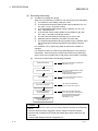
In this manual, the safety instructions are ranked as "DANGER" and "CAUTION".
DANGER
Indicates that incorrect handling may cause hazardous conditions,
resulting in death or severe injury.
! CAUTION
Indicates that incorrect handling may cause hazardous conditions,
resulting in medium or slight personal injury or physical damage.
!
Note that the ! CAUTION level may lead to a serious consequence according to the circumstances.
Always follow the instructions of both levels because they are important to personal safety.
Please save this manual to make it accessible when required and always forward it to the end user.
[Design Precautions]
!
DANGER
• Do not write data into the "read-only area" in the buffer memory of the intelligent function
module. In addition, do not turn on/off the "reserved" signals among the I/O signals transferred
to/from the PLC CPU.
Doing so can malfunction the PLC system.
• Depending on the malfunction of the external output transistor, there may be cases where the
output is ON or OFF status. Install external monitoring circuitry for output signals that may lead
to major accidents.
!
CAUTION
• Do not bunch the control wires or communication cables with the main circuit or power wires, or
install them close to each other.
They should be installed 100 mm(3.94 inch) or more from each other.
Not doing so could result in noise that may cause malfunction.
A-1
A-1
[Installation Precautions]
!
CAUTION
• Use the PLC in an environment that meets the general specifications contained in the CPU
User's Manual.
Using this PLC in an environment outside the range of the general specifications may cause
electric shock, fire, malfunction, and damage to or deterioration of the product.
• While pressing the installation lever located at the bottom of module, insert the module fixing tab
into the fixing hole in the base unit until it stops. Then, securely mount the module with the fixing
hole as a supporting point.
Improper installation may result in malfunction, breakdown or the module coming loose and
dropping. Securely fix the module with screws if it is subject to vibration during use.
• Tighten the screws within the range of specified torque.
If the screws are loose, it may cause the module to fallout, short circuits, or malfunction.
If the screws are tightened too much, it may cause damage to the screw and/or the module,
resulting in fallout, short circuits or malfunction.
• Be sure to shut off all phases of the external power supply used by the system before mounting
or removing the module.
Not ding so may cause electric shock or damage to the module.
In the system where a CPU module supporting the online module change is used and on the
MELSECNET/H remote I/O stations, modules can be replaced online (during energizing).
However, there are some restrictions on replaceable modules and the replacement procedures
are predetermined for each module.
For details, refer to the chapter of the online module change in this manual.
• Do not directly touch the conductive area or electronic components of the module.
Doing so may cause malfunction or failure in the module.
A-2
A-2
[Wiring Precautions]
!
CAUTION
• Be careful not to let foreign matters such as sawdust or wire chips get inside the module.
They may cause fires, failure or malfunction.
• The top surface of the module is covered with protective film to prevent foreign objects such as
cable offcuts from entering the module when wiring.
Do not remove this film until the wiring is complete.
Before operating the system, be sure to remove the film to provide adequate heat ventilation.
• Be sure to fix communication cables or power supply cables leading from the module by placing
them in the duct or clamping them.
Cables not placed in the duct or without clamping may hang or shift, allowing them to be
accidentally pulled, which may cause a module malfunction and cable damage.
• Do not grab on the cable when removing the communication or power cable connected to the
module.
When disconnecting a cable without a connector, first loosen the screws on the part that is
connected to the module.
Pulling the cable when it is still connected to the module may cause damage to the module or
cable, or misoperation due to cable contact failure.
• Always ground the shielded cable for the PLC.
There is a risk of electric shock or malfunction.
•·Use applicable solderless terminals and tighten them with the specified torque. If any solderless
spade terminal is used, it may be disconnected when the terminal screw comes loose, resulting
in failure.
• When wiring, be sure to verify the rated voltage of the product as well as the terminal layout. Fire
or failure may result if incorrect voltage is input or incorrect wiring is performed.
• Connecting terminals with incorrect voltage may result in malfunction or mechanical failure.
A-3
A-3
[Startup/Maintenance Precautions]
!
CAUTION
• Do not disassemble or modify the module.
Doing so could cause failure, malfunction, injury or fire.
• Be sure to shut off all phases of the external power supply used by the system before mounting
or removing the module.
Not doing so may cause failure or malfunction of the module.
In the system where a CPU module supporting the online module change is used and on the
MELSECNET/H remote I/O stations, modules can be replaced online (during energizing).
However, there are some restrictions on replaceable modules and the replacement procedures
are predetermined for each module.
For details, refer to the chapter of the online module change in this manual.
• Mounting/removing the module to/from the base and the terminal block is limited to 50 times
after using a product. (IEC61131-2-compliant)
Failure to do so may cause malfunctions.
• Do not touch the connector while the power is on.
Doing so may cause malfunction.
• Switch all phases of the external power supply off when cleaning or retightening the terminal
screws and module installation screws.
Not doing so may cause failure or malfunction of the module.
If the screws are loose, it may cause the module to fallout, short circuits, or malfunction.
If the screws are tightened too much, it may cause damages to the screws and/or the module,
resulting in the module falling out, short circuits or malfunction.
• Always make sure to touch the grounded metal to discharge the electricity charged in the body,
etc., before touching the module.
Failure to do so may cause a failure or malfunctions of the module.
[Disposal Precautions]
!
CAUTION
• When disposing of the product, handle it as industrial waste.
A-4
A-4
REVISIONS
* The manual number is given on the bottom left of the back cover.
Print Date
Oct., 2000
Jun., 2001
Manual Number
Revision
SH (NA)-080121-A First edition
SH (NA)-080121-B Standardize the name from software package (GPP function) to Product
name (GX Developer).
Standardize the name from utility package (QTCU) to Product name (GX
Configurator-TC).
Addition
Section 1.4, Section 2.1, 2.2
Correction
Feb., 2002
Conformation to the EMC Directive and Low Voltage Instruction, About
the Generic Terms and Abbreviations, Product Structure, Section 3.5.47,
Section 5.2, 5.2.1, 5.2.2, 5.3.3, 5.6
SH (NA)-080121-C Add the contents of the function version C
Addition
Chapter 7
Renumbering
Chapter 7
Chapter 8
Correction
SAFETY PRECAUTIONS, About the Generic Terms and Abbreviations,
Section 2.1, 2.2, Section 3.1.1, 3.2, 3.2.1, 3.2.10, 3.2.11, 3.5.1, 3.5.11,
3.5.20, 3.5.32, 3.5.42, Section 4.3, Section 5.2.1, 5.2.2, Section 6.2.2,
6.3, Section 8.1
Aug., 2002
SH (NA)-080121-D Correction
Section 2.1, Section 3.1, 3.2.1, 3.2.7, 3.5.1, 3.5.12, 3.5.15, 3.5.20, 3.5.26,
3.5.34, 3.5.35, 3.5.44, 3.5.45, 3.5.49, 3.5.51, 3.5.52, Section 6.3, Section
8.10
Feb., 2003
SH (NA)-080121-E Correction
SAFETY PRECAUTIONS, INTRODUCTION, CONTENTS, Section 2.1,
Section 3.1.1, Section 3.5.38, Section 5.2.2, Section 5.3.3, Section 5.4 to
Section 5.6
May, 2003
SH (NA)-080121-F Correction
Section 2.1, Section 3.5.15, Section 3.5.36, Section 6.3
May, 2004
SH (NA)-080121-G
Addition of program example for use on the remote I/O network
Correction
Section 2.1, 2.2, Section 3.5.4, Chapter 6, Section 7.1, 7.3.1, 7.3.2
Oct., 2004
SH (NA)-080121-H Correction
SAFETY PRECAUTIONS, Section 2.1, Section 3.1.1, 3.2.1,
Section 4.1, Section 6.3, 6.3.1, Section 8.1
A-5
A-5
Print Date
Manual Number
Jul., 2005
SH (NA)-080121-I
Revision
Correction
SAFETY PRECAUTIONS, Conformation to the EMC Directive and Low
Voltage Instruction, Section 1.3.4, Section 2.1, 2.2, Section 3.1.1, 3.2.11,
3.4.3, 3.5.2, 3.5.8, Section 4.5, Section 5.1, 5.2.1, 5.3.2, 5.3.3, 5.4, 5.5,
5.6, Section 6.2, 6.2.1, 6.3, 6.3.1, Section 7.2, 7.3.1, 7.3.2, Section 8.10
Mar., 2006
SH(NA)-080121-J
Correction
SAFETY PRECAUTIONS, Conformation to the EMC Directive and Low
Voltage Instruction, Section 3.5.26
Japanese Manual Version SH-080108-L
This manual confers no industrial property rights or any rights of any other kind, nor does it confer any patent
licenses. Mitsubishi Electric Corporation cannot be held responsible for any problems involving industrial property
rights which may occur as a result of using the contents noted in this manual.
© 2000 MITSUBISHI ELECTRIC CORPORATION
A-6
A-6
INTRODUCTION
Thank you for the purchasing the MELSEC-Q series PLC.
Before using the equipment, please read this manual carefully to develop full familiarity with the functions
and performance of the Q series PLC you have purchased, so as to ensure correct use.
CONTENTS
SAFETY PRECAUTIONS .............................................................................................................................A- 1
REVISIONS....................................................................................................................................................A- 4
INTRODUCTION............................................................................................................................................A- 7
CONTENTS....................................................................................................................................................A- 7
Conformance with the EMC and Low Voltage Directives.............................................................................A-11
About the Generic Terms and Abbreviations ................................................................................................A-12
Product Structure ...........................................................................................................................................A-12
1 GENERAL DESCRIPTION
1- 1 to 1-12
1.1 Features ................................................................................................................................................... 1- 3
1.2 The PID Control System .......................................................................................................................... 1- 5
1.3 About the PID Operation.......................................................................................................................... 1- 6
1.3.1 Operation method and formula......................................................................................................... 1- 6
1.3.2 The Q64TC actions ........................................................................................................................... 1- 7
1.3.3 Proportional action (P-action) ........................................................................................................... 1- 8
1.3.4 Integral action (I-action) .................................................................................................................... 1- 9
1.3.5 Derivative action (D-action)............................................................................................................... 1-10
1.3.6 PID action .......................................................................................................................................... 1-11
1.4 Functions Added to Function Version B and Later ................................................................................. 1-12
2 SYSTEM CONFIGURATION
2- 1 to 2- 4
2.1 Applicable Systems.................................................................................................................................. 2- 1
2.2 How to Check the Function Version and Software Version ................................................................... 2- 3
3 SPECIFICATIONS
3- 1 to 3-48
3.1 Performance Specifications ..................................................................................................................... 3- 1
3.1.1 Performance specifications of the Q64TC ....................................................................................... 3- 1
3.1.2 Usable temperature sensor types, measurement temperature ranges and data resolutions ........ 3- 3
3.2 Function Summary................................................................................................................................... 3- 4
3.2.1 Auto tuning function .......................................................................................................................... 3- 5
3.2.2 Reverse/Forward action select function ........................................................................................... 3- 9
3.2.3 RFB limiter function........................................................................................................................... 3- 9
3.2.4 Sensor compensation function ......................................................................................................... 3- 9
3.2.5 Unused channel setting .................................................................................................................... 3-10
3.2.6 Forced PID control stop .................................................................................................................... 3-10
3.2.7 Heater disconnection detection function (supported only by Q64TCTTBW, Q64TCRTBW) ......... 3-11
3.2.8 Output off-time current error detection function
(available for Q64TCTTBW and Q64TCRTBW only)..................................................................... 3-12
3.2.9 Loop disconnection detection function ............................................................................................. 3-12
A-7
A-7
3.2.10 Data storage on E2PROM............................................................................................................... 3-13
3.2.11 Alert alarms ..................................................................................................................................... 3-15
3.2.12 Control output setting at CPU stop error occurrence..................................................................... 3-19
3.2.13 Q64TC control status controlling output signal and
buffer memory settings and control status..................................................................................... 3-20
3.3 Sampling Period and Control Output Period........................................................................................... 3-21
3.4 I/O Signals Transferred to/from the PLC CPU........................................................................................ 3-22
3.4.1 I/O signal list ...................................................................................................................................... 3-22
3.4.2 Input signal functions ........................................................................................................................ 3-23
3.4.3 Output signal functions...................................................................................................................... 3-26
3.5 Buffer Memory.......................................................................................................................................... 3-28
3.5.1 Buffer memory list ............................................................................................................................. 3-28
3.5.2 Write data error code (buffer memory address: 0H)......................................................................... 3-30
3.5.3 Decimal point position (buffer memory address: 1H to 4H) .............................................................. 3-30
3.5.4 Alert definition (buffer memory address: 5H to 8H) ........................................................................... 3-31
3.5.5 Temperature process value (PV value, buffer memory address: 9H to CH) .................................... 3-31
3.5.6 Manipulated value (MV value, buffer memory address: DH to 10H) ................................................ 3-32
3.5.7 Temperature rise judgment flag (buffer memory address: 11H to 14H) ........................................... 3-32
3.5.8 Transistor output flag (buffer memory address: 15H to 18H)............................................................ 3-32
3.5.9 Cold junction temperature process value (buffer memory address: 1DH)....................................... 3-33
3.5.10 MAN mode shift completion flag (buffer memory address: 1EH)................................................... 3-33
3.5.11 E2PROM's PID constant read/write flag (buffer memory address: 1FH) ....................................... 3-34
3.5.12 Input range (buffer memory address: 20H, 40H, 60H, 80H)............................................................. 3-35
3.5.13 Stop mode setting (buffer memory address: 21H, 41H, 61H, 81H).................................................. 3-36
3.5.14 Set value (SV) setting (buffer memory address: 22H, 42H, 62H, 82H)............................................ 3-37
3.5.15 PID constant setting
(buffer memory address: 23H to 25H, 43H to 45H, 63H to 65H, 83H to 85H) ................................... 3-37
3.5.16 Alert alarm 1 to 4 setting
(buffer memory address: 26H to 29H, 46H to 49H, 66H to 69H, 86H to 89H) ................................... 3-37
3.5.17 Upper/lower output limiter setting
(buffer memory address: 2AH, 2BH, 4AH, 4BH, 6AH, 6BH, 8AH, 8BH) ............................................ 3-37
3.5.18 Output variation limiter setting (buffer memory address: 2CH, 4CH, 6CH, 8CH) ............................ 3-38
3.5.19 Sensor compensation value setting (buffer memory address: 2DH, 4DH, 6DH, 8DH) ................... 3-38
3.5.20 Adjustment sensitivity (dead band) setting (buffer memory address: 2EH, 4EH, 6EH, 8EH) ......... 3-38
3.5.21 Control output period setting (buffer memory address: 2FH, 4FH, 6FH, 8FH) ................................ 3-39
3.5.22 Primary delay digital filter setting (buffer memory address: 30H, 50H, 70H, 90H) .......................... 3-39
3.5.23 Control response parameter setting (buffer memory address: 31H, 51H, 71H, 91H) ..................... 3-40
3.5.24 AUTO/MAN setting (buffer memory address: 32H, 52H, 72H, 92H)................................................ 3-40
3.5.25 MAN output setting (buffer memory address: 33H, 53H, 73H, 93H) ................................................ 3-41
3.5.26 Setting change rate limiter setting (buffer memory address: 34H, 54H, 74H, 94H)......................... 3-41
3.5.27 AT bias setting (buffer memory address: 35H, 55H, 75H, 95H) ....................................................... 3-41
3.5.28 Forward/reverse action setting (buffer memory address: 36H, 56H, 76H, 96H).............................. 3-42
3.5.29 Upper/lower setting limiter
(buffer memory address: 37H, 38H, 57H, 58H, 77H, 78H, 97H, 98H)................................................ 3-42
3.5.30 Heater disconnection alert setting (buffer memory address: 3AH, 5AH, 7AH, 9AH)....................... 3-42
3.5.31 Loop disconnection detection judgment time setting
(buffer memory address: 3BH, 5BH, 7BH, 9BH) .............................................................................. 3-42
3.5.32 Loop disconnection detection dead band setting
(buffer memory address: 3CH, 5CH, 7CH, 9CH) ............................................................................. 3-43
A-8
A-8
3.5.33 Unused channel setting (buffer memory address: 3DH, 5DH, 7DH, 9DH) ...................................... 3-43
3.5.34 E2PROM's PID constant read command (buffer memory address: 3EH, 5EH, 7EH, 9EH) ............ 3-43
3.5.35 Automatic backup setting after auto tuning of PID constants
(buffer memory address: 3FH, 5FH, 7FH, 9FH) ............................................................................... 3-44
3.5.36 Alert dead band setting (buffer memory address: A4H) ................................................................. 3-44
3.5.37 Alert delay count setting (buffer memory address: A5H)................................................................ 3-44
3.5.38 Heater disconnection/output off-time current detection delay count setting
(buffer memory address: A6H)........................................................................................................ 3-44
3.5.39 Temperature rise completion range setting (buffer memory address: A7H) ................................. 3-45
3.5.40 Temperature rise completion soak time setting (buffer memory address: A8H) ........................... 3-45
3.5.41 PID continuation flag (buffer memory address: A9H)..................................................................... 3-45
3.5.42 Heater disconnection compensation function selection (buffer memory address: AAH) .............. 3-45
3.5.43 Transistor ON delay output delay time setting (buffer memory address: AFH)............................. 3-45
3.5.44 CT monitor method switching (buffer memory address: B0H) ....................................................... 3-46
3.5.45 Manipulated value
(MV value, 0 to 4000/0 to 12000/0 to 16000, buffer memory address: B1H to B4H) .................... 3-46
3.5.46 Manipulated value resolution switching (buffer memory address: B5H)........................................ 3-46
3.5.47 Auto tuning mode selection (buffer memory address: B8H to BBH) .............................................. 3-46
3.5.48 Alert alarm 1 to 4 mode setting
(buffer memory address: C0H to C3H, D0H to D3H, E0H to E3H, F0H to F3H)................................ 3-47
3.5.49 Heater current measurement value (buffer memory address: 100H to 107H)............................... 3-47
3.5.50 CT input channel assignment setting (buffer memory address: 108H to 10FH) ............................ 3-48
3.5.51 CT selection (buffer memory address: 110H to 117H).................................................................... 3-48
3.5.52 Reference heater current value (buffer memory address: 118H to 11FH) ..................................... 3-48
4 SETUP AND PROCEDURE BEFORE STARTING THE OPERATION
4- 1 to 4-13
4.1 Handling Precautions............................................................................................................................... 4- 1
4.2 Procedure Before Starting the Operation................................................................................................ 4- 2
4.3 Parts Identification.................................................................................................................................... 4- 3
4.4 Wiring........................................................................................................................................................ 4- 6
4.4.1 Wiring precautions............................................................................................................................. 4- 6
4.4.2 External wiring ................................................................................................................................... 4- 7
4.4.3 Heater disconnection detection wiring and setting example for use of three-phase heater........... 4-11
4.5 Switch Settings for the Intelligent Function Module ................................................................................ 4-12
5 UTILITY PACKAGE (GX Configurator-TC)
5- 1 to 5-19
5.1 Utility Package Functions ........................................................................................................................ 5- 1
5.2 Installing and Uninstalling the Utility Package ........................................................................................ 5- 3
5.2.1 User precautions ............................................................................................................................... 5- 3
5.2.2 Operating environment ..................................................................................................................... 5- 5
5.3 Explanation of Utility Package Operations.............................................................................................. 5- 6
5.3.1 How to perform common utility package operations........................................................................ 5- 6
5.3.2 Operation overview ........................................................................................................................... 5- 8
5.3.3 Starting the intelligent function utility ................................................................................................ 5-10
5.4 Initial Settings ........................................................................................................................................... 5-12
5.5 Auto Refresh ............................................................................................................................................ 5-15
5.6 Monitor/Test ............................................................................................................................................. 5-17
A-9
A-9
6 PROGRAMMING
6- 1 to 6-13
6.1 Programming Procedure.......................................................................................................................... 6- 1
6.2 For Use in Nomal System Configulation ................................................................................................. 6- 2
6.2.1 Program example using the utility package ..................................................................................... 6- 3
6.2.2 Program example without using the utility package......................................................................... 6- 5
6.3 For Use in Remote I/O Network .............................................................................................................. 6- 7
6.3.1 Program example using the utility package ..................................................................................... 6- 8
6.3.2 Program example without using the utility package......................................................................... 6-11
7 ONLINE MODULE CHANGE
7- 1 to 7-14
7.1 Online Module Change Conditions.......................................................................................................... 7- 2
7.2 Online Module Change Operations......................................................................................................... 7- 3
7.3 Online Module Change Procedure.......................................................................................................... 7- 4
7.3.1 GX Configurator-TC was used for initial setting............................................................................... 7- 4
7.3.2 Sequence program was used for initial setting ................................................................................ 7- 9
7.4 Precautions for Online Module Change .................................................................................................. 7-14
8 TROUBLESHOOTING
8- 1 to 8- 8
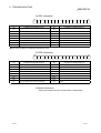
8.1 Error Code List ......................................................................................................................................... 88.2 Processing Performed by Q64TC at Error Occurrence.......................................................................... 88.3 If the RUN LED Has Flickered or Turned Off.......................................................................................... 88.4 If the ERR. LED Has Turned On or Flickered......................................................................................... 88.5 If the ALM LED Has Turned On or Flickered .......................................................................................... 88.6 If the Module Ready Flag (Xn0) Does Not Turn ON............................................................................... 88.7 If the Write Error Flag (Xn2) Has Turned ON.......................................................................................... 88.8 If the Hardware Error Flag (Xn3) Has Turned ON .................................................................................. 88.9 If the Alert Occurrence Flag (XnC to XnF) Has Turned ON ................................................................... 88.10 Checking the Q64TC Status by System Monitoring of GX Developer................................................. 8APPENDIX
1
2
3
3
3
4
4
4
4
5
Appendix- 1 to Appendix- 3
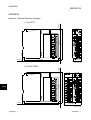
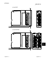
Appendix 1 External Dimension Diagram ........................................................................................Appendix- 1
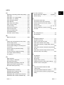
INDEX
A - 10
Index- 1 to Index- 2
A - 10
Conformance with the EMC and Low Voltage Directives
When incorporating a Mitsubishi PLC that is compliant with the EMC and low voltage
directives into any other product and ensuring compliance with these directives, refer
to Chapter 3 “EMC and Low Voltage Directives” of the User's Manual (Hardware) for
the PLC CPU included with the CPU module or base unit.
The CE logo is printed on the rating plate on the main body of the PLC that conforms
to the EMC directive and low voltage instruction.
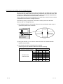
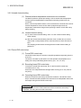
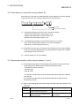
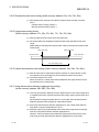
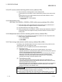
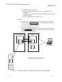
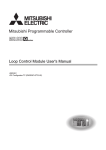
The following wiring is required for conformance of this product with the EMC
Directive and Low Voltage Directive.
(1) Use shielded cables for all external wiring and use the AD75CK cable clamp to
ground this product to an enclosure.
Inside control box
AD75CK
Q64TC
Strip the sheath.
20cm (7.88 inch) to
30cm (11.82 inch)
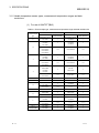
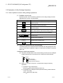
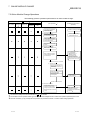
(2) Using the AD75CK, you can tie four cables of about 7mm outside diameter
together for grounding.
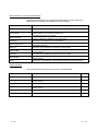
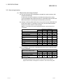
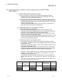
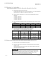
(3) The following number of AD75CKs will be needed.
(Assuming that 7mm-diameter cables are used for all wiring)
Number of AD75CKs needed
Number of CT
channels used
A - 11
0
1
2
3
4
5
6
7
8
Number of channels used
1
2
3
4
1
1
2
2
1
2
2
3
1
2
2
3
2
2
3
3
2
2
3
3
2
3
3
4
2
3
3
4
3
3
4
4
3
3
4
4
A - 11
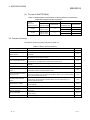
About the Generic Terms and Abbreviations
Unless otherwise specified, this manual uses the following generic terms and
abbreviations to describe the Temperature control module.
Generic term/abbreviation
Personal computer
GX Developer
QCPU (Q mode)
Description
DOS/V-compatible personal computer of IBM PC/AT or its compatible
R
Generic product name of the product types SWnD5C-GPPW-E, SWnD5C-GPPW-EA,
SWnD5C-GPPW-EV and SWnD5C-GPPW-EVA.
"n" in the model name is 4 or greater.
Generic term of the Q00JCPU, Q00CPU, Q01CPU, Q02CPU, Q02HCPU, Q06HCPU,
Q12HCPU, Q25HCPU, Q12PHCPU and Q25PHCPU.
QnPHCPU
Generic term of the Q12PHCPU and Q25PHCPU.
GX Configurator-TC
Generic term of temperature control module setting/monitoring tool GX ConfiguratorTC(SW0D5C-QTCU-E)
Q64TCTT
Abbreviation of Type Q64TCTT temperature control module
Q64TCTTBW
Abbreviation of Type Q64TCTTBW temperature control module with disconnection
detection function
Q64TCRT
Abbreviation of Type Q64TCRT temperature control module
Q64TCRTBW
Abbreviation of Type Q64TCRTBW temperature control module with disconnection
detection function
Q64TC
Generic term of Type Q64TCTT, Q64TCTTBW, Q64TCRT and Q64TCRTBW
Product Structure
The product structure of the product is given in the table below.
Model code
Product name
Quantity
Q64TCTT
Type Q64TCTT temperature control module
1
Q64TCTTBW
Type Q64TCTTBW temperature control module with disconnection
detection function
1
Q64TCRT
Type Q64TCRT temperature control module
1
Q64TCRTBW
Type Q64TCRTBW temperature control module with disconnection
detection function
1
SW0D5C-QTCU-E
GX Configurator-TC Version 1 (1-license product)
(CD-ROM)
1
SW0D5C-QTCU-EA
GX Configurator-TC Version 1 (Multiple-license product)
(CD-ROM)
1
A - 12
A - 12
1 GENERAL DESCRIPTION
MELSEC-Q
1 GENERAL DESCRIPTION
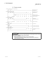
This manual deals with the specifications, handling and instructions wiring and
programming methods of the following temperature control modules used with the
MELSEC-Q series PLC CPU module (hereafter abbreviated to the PLC CPU).
• Type Q64TCTT temperature control module
• Type Q64TCRT temperature control module
• Type Q64TCTTBW temperature control module with disconnection detection function
• Type Q64TCRTBW temperature control module with disconnection detection function
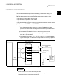
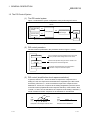
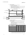
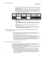
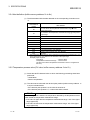
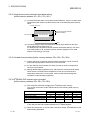
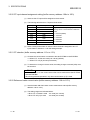
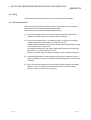
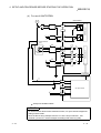
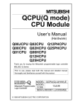
(1) What are Q64TCTT and Q64TCRT?
(a) The Q64TCTT and Q64TCRT are modules designed to convert input values
from external temperature sensors into 16-bit signed BIN (binary) data,
perform PID operations to attain target temperatures, and provide transistor
outputs for temperature control.
(b) The Q64TCTT and Q64TCRT have an auto tuning function which
automatically sets the proportional band (P), integral time (I) and derivative
time (D) for PID operations.
(c) The Q64TCTT accepts K, J, T, B, S, E, R, N, U, L, PL II and W5Re/W26Re
type thermocouples. The Q64TCRT accepts Pt100 and JPt100 type platinum
temperature-measuring resistors.
Q64TCTT,Q64TCRT
PLC CPU
Initial
setting
Manipulated
value
Set value
(TO
instruction)
Set value
PID
operation
Process
value
Manipulated
Process value
value
Buffer memory
CH1
CH1
CH4
CH1
Manipulated value
Input from temperature
sensor
Transistor output
(ON/OFF pulse)
CH1
CH4
CH1
CH4
Temperature
Device
to be
controlled
Fig. 1.1 Q64TCTT or Q64TCRT Processing Outline
REMARK
1) Refer to Section 3.2.1 for the auto tuning function
2) Refer to Section 3.1.2 for the measured temperature ranges of the temperature
sensors that can be connected to the Q64TC.
1-1
1-1
1
1 GENERAL DESCRIPTION
MELSEC-Q
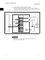
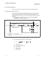
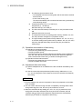
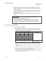
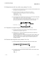
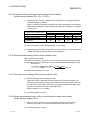
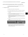
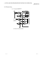
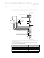
(2) What are Q64TCTTBW and Q64TCRTBW?
The Q64TCTTBW and Q64TCRTBW are Q64TCTT and Q64TCRT-based
modules which have the additional function to detect a heater wire disconnection
using inputs from external current sensors.
1
Q64TCTTBW,Q64TCRTBW
PLC CPU
Initial
setting
Manipulated
value
Set value
(TO
instruction)
Set value
PID
operation
Process
value
Manipulated Process value
value
Buffer memory
CH1
CH1
CH4
CH1
Manipulated value
Input from temperature
sensor
Transistor output
(ON/OFF pulse)
CH1
CH4
Current
sensor
CH1
Temperature
Device
to be
controlled
CH4
Alarm
CH1
Disconnection
detection
CH4
Fig. 1.2 Q64TCTTBW or Q64TCRTBW Processing Outline
REMARK
1) Refer to Section 3.2.7 for the disconnection detection function of the
Q64TCTTBW and Q64TCRTBW.
1-2
1-2
1 GENERAL DESCRIPTION
MELSEC-Q
1.1 Features
The Q64TC has the following features.
(1) Optimum temperature adjustment control (PID control)
(a) The Q64TC exercises temperature adjustment control automatically by
merely setting the PID constants (proportional band (P), integral time (I),
derivative time (D)) and temperature set value (set value: SV) necessary for
PID operations.
Therefore, no special instructions are needed to perform PID control.
(b) Using the auto tuning function enables the PID constants to be set
automatically by the Q64TC.
Hence, you can use the equipment without being conscious of cumbersome
PID operation expressions to find the PID constants.
(2) 4 loops on 1 module
The module provides a maximum of four loops at the same time for temperature
adjustment control.
(3) RFB limiter function
The RFB (Reset FeedBack) limiter suppresses overshooting which is liable to
occur at a startup or when a temperature set value (SV) is increased.
(4) Sensor compensation function
By setting a sensor compensation value, the sensor compensation function
eliminates a difference between a temperature process value (PV) and an actual
temperature, if any.
(5) Connection of thermocouples compatible with JIS, IEC, NBS,
ASTM and DIN Standards
(a) The Q64TCTT(BW) accepts the following thermocouples compatible with the
JIS, IEC, NBS, ASTM and DIN Standards.
• JIS Standards : R, K, J, S, B, E, T • IEC Standards: R, K, J, S, B, E, T, N
• NBS Standards : PL II
• ASTM Standards: W5re, W23re
• DIN Standards : U, L
(b) The Q64TCTT(BW) allows you to set the temperature measurement ranges
which meet the operating temperatures of the above thermocouples.
(6) Connection of Pt100 and JPt100 platinum temperature-measuring
resistors
The Q64TCTT(BW) allows you to set the temperature measurement ranges
which meet the operating temperatures of the Pt100 and JPt100.
1-3
1-3
1 GENERAL DESCRIPTION
MELSEC-Q
(7) Choice of fine temperature measurement units and various control
temperature ranges
The temperature measurement unit of each loop can be set to 1°C or 0.1°C in
Centigrade or to 1°F or 0.1°F in Fahrenheit, enabling you to choose appropriate
resolution for control. Also, the controllable temperature range can be selected
from 0.0 to 400.0°C (when K type thermocouple is used), 0.0 to 3000.0°C (when
R type thermocouple is used) and others, enabling you to make adequate setting
for the object to be controlled.
2
(8) E PROM for backing up set values
The set values in buffer memory can be stored into E2PROM for data backup.
Using the test function of GX Developer to write data directly to the buffer
memory, what is required in a sequence program is "LD
" + "OUT Yn1" at the
minimum.
(9) Detection of disconnection
The Q64TCTTBW and Q64TCRTBW can detect the disconnection of a heater.
(10) Utility package for ease of setting
The optional utility package (GX Configurator-TC) is available.
Though you are not required to use the utility package, it allows initial and
automatic refresh settings to be made on the screen, reducing sequence
programs and also enabling you to check the setting and operating states and
execute auto tuning easily.
1-4
1-4
1 GENERAL DESCRIPTION
MELSEC-Q
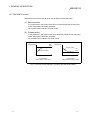
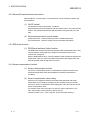
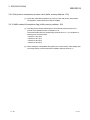
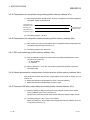
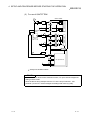
1.2 The PID Control System
(1) The PID control system
Figure 1.3 indicates the system configuration when performing PID control.
Q64TC
Set value data
storage
SV
MV
PID operation
process value
data storage
Manipulated value
data storage
Control
object
PV
Sensor
Fig. 1.3 The PID control system
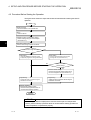
(2) PID control procedure
The PID control is performed in the procedure shown in Figure 1.4 below:
Read the PV value
Import a signal from the temperature sensor and write
it to the process value storage area as a PV value.
Perform PID
operation
Perform PID operation using the SV/PV values in the
set value/process value storage area.
Convert MV value obtained by the PID operation
to transistor -output on time and output it.
Output MV
Fig. 1.4 PID control procedure
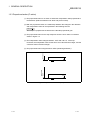
(3) PID control (simplified two-level response selection)
In general, when the P, I, and D constants to improve the "response to the
setting" are set, the "response to the disturbance" degrades by the PID control.
Conversely, when the P, I, and D constants to improve the "response to the
disturbance" are set, the "response to the setting" degrades by the PID control.
In the PID control (simplified two-level response selection) of this module, "fast",
"normal", or "slow" can be selected for the "response to the setting" while the P, I,
and D constants for better "response for the disturbance" are selected.
Fast
Set
value
(SV)
Normal
Slow
Response to the change of the set value
Set
value
(SV)
Response to the disturbance
Fig. 1.5 simplified two-level response selection
1-5
1-5
1 GENERAL DESCRIPTION
MELSEC-Q
1.3 About the PID Operation
The Q64TC can perform PID control in process-value incomplete differentiation.
1.3.1 Operation method and formula
The PID control in process-value incomplete differentiation is an operation method
which puts the first-order delay filter as the input for derivative control action, and
performs PID operation with the error value (E) after deleting the high-frequency noise
component.
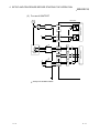
(1) The algorithm of the PID control in process-value incomplete
differentiation is shown in Figure 1.6.
Disturbance D
Q64TC
SV(Set value)
Control response
parameters
Slow
Normal control
Fast
+
Kp(1+
1
Ti s
Control object
+
)
-
G(s)
MV
-
Kp TD s
1+
TD
S
PV(Process value)
Kp : Proportional gain
: Derivative gain
S : Laplace transform conversion
Ti : Integral time
TD : Derivative time
Fig. 1.6 Algorithm of PID control in process-value incomplete differentiation
(2) The formula used for Q64TC is shown below:
MV n = MV n-1 +
TD
+
TD
(PV n-1 - PV n) -
TD
MV n-1
: Sampling period
MV : Incomplete derivative output
PV : Process value
TD : Derivative time
1
1-6
: Derivative gain
1-6
1 GENERAL DESCRIPTION
MELSEC-Q
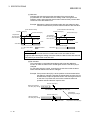
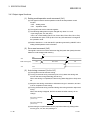
1.3.2 The Q64TC actions
The Q64TC performs PID operations in reverse action and forward action.
(1) Reverse action
In a reverse action, the process value (PV) increases toward the set value (SV)
as the manipulation value (MV) increases.
The reverse action is effective for heat control.
(2) Forward action
In a forward action, the process value (PV) decreases toward the set value (SV)
as the manipulation value (MV) increases.
The forward action is effective for cooler control.
Set
value
Temperature
Temperature
Process value
Set
value
Process value
Time
Reverse action
(when used for heat control)
Time
Forward action
(when used for cooling control)
Fig. 1.7 Process control example in reverse action and forward action
1-7
1-7
1 GENERAL DESCRIPTION
MELSEC-Q
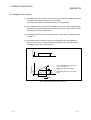
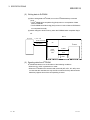
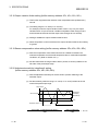
1.3.3 Proportional action (P-action)
(1) The proportional action is an action to obtain the manipulation value proportional to
the deviation (difference between set value and process value).
(2) With the proportional action, the relationship between the changes in the deviation
and manipulation value can be expressed in the following formula:
MV = KP E
where Kp is a proportional constant and is called the proportional gain.
(3) The proportional action for the step response when the error value is constant is
shown in Figure 1.8.
(4) The manipulation value changes between -5.0% and 105.0 %. As the Kp
increases, the manipulation value for the same error value becomes larger, and the
corrective action becomes stronger.
Deviation
(5) The proportional action will generate an offset (remaining deflection).
E
Manipulated
value
Time
KP E
Time
Fig. 1.8 Proportional action for step response
1-8
1-8
1 GENERAL DESCRIPTION
MELSEC-Q
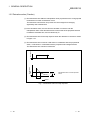
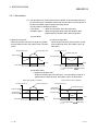
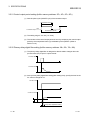
1.3.4 Integral action (I-action)
(1) The integral action is an action which continuously changes the manipulation value
to eliminate the deviation when there is an deviation.
The offset produced by the proportional action can be eliminated.
(2) In the integral action, the time from the deviation occurrence until the manipulation
value of the integral action becomes that of the proportional control action is called
the integral time, and is indicated by TI.
(3) The integral action for the step response when the error value is constant is shown
in Figure 1.9.
Deviation
(4) The integral action is used as a PI action in combination with the proportional
action, or PID action in combination with the proportional and derivative actions.
The integral action cannot be used alone.
E
Time
Manipulated
value
Manipulated value of the Proportional
action + Integral action
KP E
Manipulated value of the Integral
action
Manipulated value of the Proportional
action
TI
Time
Fig. 1.9 Integral action for step response
1-9
1-9
1 GENERAL DESCRIPTION
MELSEC-Q
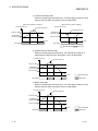
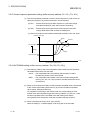
1.3.5 Derivative action (D-action)
(1) The derivative action adds the manipulation value proportional to the change speed
to eliminate error when an deviation occurs.
The derivative control action can prevent the control target from changing
significantly due to disturbance.
(2) In the derivative action, the time from the deviation occurrence until the
manipulation value of the derivative action becomes that of the proportional action
is called the derivative time, and is indicated by TD.
(3) The derivative action for the step response when the deviation is constant is shown
in Figure 1.10.
Deviation
(4) The derivative action is used as a PD action in combination with the proportional
action, or PID action in combination with the proportional and integral actions.
The derivative action cannot be used alone.
E
Manipulated
value
Time
KP E
Manipulated value of the Proportional
action
TD
Time
Fig. 1.10 Derivative action for step response
1 - 10
1 - 10
1 GENERAL DESCRIPTION
MELSEC-Q
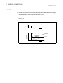
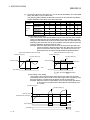
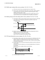
1.3.6 PID action
(1) The PID action performs control using the manipulation value obtained by merging
proportional action, integral action and derivative action.
Deviation
(2) The PID action for the step response when the deviation is constant is shown in
Figure 1.11.
Time
Manipulated
value
PID action
PI action
I action
P action
D action
Time
Fig. 1.11 PID action for step response
1 - 11
1 - 11
1 GENERAL DESCRIPTION
MELSEC-Q
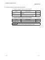
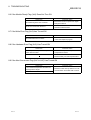
1.4 Functions Added to Function Version B and Later
(1) Functions added to function version B Q64TC
Function
Function summary
Multiple PLC system
Control from any desired PLC CPU by a multiple
support
PLC system.
Auto tuning mode selection
Auto tuning mode selection corresponding to the
response characteristics of the control object.
Reference
section
—
Section 3.5.47
(2) Functions added to function version C Q64TC
Function
Online module change
Function summary
Change the module without stopping the system.
Reference
section
Chapter 7
POINT
See Section 2.2 for the confirmation methods of the function version.
1 - 12
1 - 12
2 SYSTEM CONFIGURATION
MELSEC-Q
2 SYSTEM CONFIGURATION
This chapter explains the system configuration of the Q64TC.
2.1 Applicable Systems
(1) Applicable modules and numbers of Q64TC modules that may be
mounted
The following table indicates the CPU modules and network modules (for remote
I/O stations) which accept the Q64TC, and the number of Q64TC modules that
can be mounted.
Number of modules that can be installed
Applicable module
CPU module
Network module
Remarks
Q64TCTT/
Q64TCRT
Q64TCTTBW/
Q64TCRTBW
Q00JCPU
Maximum 16
Maximum 8
Q00CPU
Q01CPU
Maximum 24
Maximum 12
Q02CPU
Q02HCPU
Q06HCPU
Q12HCPU
Q25HCPU
Maximum 64
Maximum 32
Q12PHCPU
Q25PHCPU
Maximum 64
Maximum 32
( 1)
QJ72LP25-25
QJ72BR15
QJ72LP25G
QJ72LP25GE
Maximum 64
Maximum 32
MELSECNET/H Remote
I/O station ( 2)
( 1)
Can be installed in Q
mode only ( 1)
1 See User's Manual (Function Explanation, Program Fundamentals) for the CPU module to use.
2 See Q Corresponding MELSECNET/H Network System Reference Manual (Remote I/O
network).
(2) Base unit which the conversion can be installed
The Q64TC can be mounted in any I/O slot ( 3) of a base unit.
However, combining it with other mounted modules may result in a power supply
shortage depending on the number of modules to be mounted. Thus, always
take into consideration the power supply capacity when mounting modules.
3 Within the I/O point ranges of the CPU modules and network modules (for
remote I/O stations)
(3) Compatibility with a multiple PLC system
First read the QCPU User's Manual (Function Explanation, Program
Fundamentals) if the Q64TC is used with a multiple PLC system.
(a) Compatible Q64TC
Use a Q64TC with function version B or higher if using the module in a
multiple PLC system.
(b) Intelligent function module parameters
Perform PLC write of the intelligent function module parameters to the
control PLC of the Q64TC only.
2-1
2-1
2
2 SYSTEM CONFIGURATION
MELSEC-Q
(4) Compatibility with online module change
To make an online module change, use the module of function version C or later.
POINT
The products of function version C include the functions of the products function
versions A and B.
2
(5) Software packages supported
Correspondence between systems which use Q64TC and software packages are
as shown below.
The GX Developer is necessary when using a Q64TC.
Software Version
GX Developer
Single PLC
Q00J/Q00/Q01CPU
system
Multiple PLC
system
Single PLC
Q02/Q02H/Q06H/
system
Q12H/Q25HCPU
Multiple PLC
system
Version 7 or later
Version 8 or later
Version 4 or later
Version 6 or later
Single PLC
Q12PH/Q25PHCPU
system
Multiple PLC
remote I/O station
Version 1.10L or later
(cannot be used with the
SW0D5C-QTCU-E 30D or
earlier versions).
SW0D5C-QTCU-E 00A or
later
SW0D5C-QTCU-E 30D or
later
Version 1.13P or later
Version 7.10L or later
(cannot be used with the
SW0D5C-QTCU-E 30D or
earlier versions).
system
If installed in a MELSECNET/H
GX Configurator-TC
Version 6 or later
SW0D5C-QTCU-E 30D or
later
(6) Current sensors
Only the following current sensors of URD, Ltd. are usable with the Q64TCTTBW
and Q64TCRTBW.
• CTL-12-S36-8(0.0 to 100.0A)
• CTL-6-P-H(0.0 to 20.00A) (The conventional model CTL-6-P is also usable.)
2-2
2-2
2 SYSTEM CONFIGURATION
MELSEC-Q
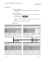
2.2 How to Check the Function Version and Software Version
This section describes how to check the function version of the Q64TC and the GX
Configuration-TC software version.
(1) How to check the function version of the Q64TC
(a) To check the version using the "SERIAL column of the rating plate" located
on the side of the module
Function version
Conformed standard
(b) To check the version using the GX Developer
See Section 8.10 of this manual.
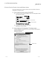
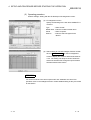
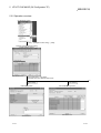
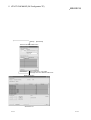
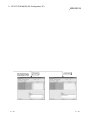
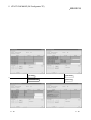
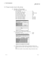
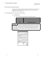
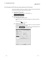
(2) How to check the GX Configuration-TC software version
The GX Configuration-TC software version can be checked in GX Developer's
"Product information" screen.
[Startup procedure]
GX Developer
"Help"
Product information
Software version
(In the case of GX Developer Version 7)
2-3
2-3
2 SYSTEM CONFIGURATION
MELSEC-Q
REMARK
The version indication for the GX Configurator-TC has been changed as shown
below from the SW0D5C-QTCU-E 30D upgrade product.
Previous product
Upgrade and subsequent versions
SW0D5C-QTCU-E 30D
GX Configurator-TC Version 1.10L
2-4
2-4
3 SPECIFICATIONS
MELSEC-Q
3 SPECIFICATIONS
This chapter provides the performance specifications of the Q64TC, I/O signals
transferred to/from the PLC CPU and the specifications of buffer memory.
For the general specifications of the Q64TC, refer to the User's Manual (hardware) of
the CPU module used.
3.1 Performance Specifications
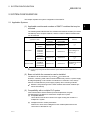
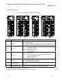
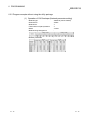
3.1.1 Performance specifications of the Q64TC
Table 3.1 Q64TC performance specification list
Q64TCTT
Control output
Number of temperature input points
Usable thermocouples/platinum
temperature-measuring resistors
Ambient
temperature:
25°C±5°C
Indication
Ambient
accuracy
temperature:
0 to 55°C
Temperature
measurement
Accvalue:
uracy Cold junction -100°C or more
temperature
1
Temperature
compensation
measurement
accuracy
value:
(Ambient
-150 to -100°C
temperature:
Temperature
0 to 55°C)
measurement
value:
-200 to -150°C
Sampling period
Control output period
Input impedance
Input filter
Sensor compensation value setting
Operation at sensor input
disconnection
Temperature control system
PID constant setting
PID constant Proportional band (P)
range
Integral time (I)
Derivative time (D)
Set value setting range
Dead band setting range
Output signal
Rated load voltage
Max. load current
Transistor
Max. inrush current
output
Leakage current at OFF
Max. voltage drop at ON
Response time
2
E PROM write count
Insulation method
Dielectric strength
Insulation resistance
3-1
Specifications
Q64TCRT
Q64TCTTBW
Transistor output
4 channels/module
Q64TCRTBW
Refer to Section 3.1.2.
Full-scale x (±0.3%)
Full-scale x (±0.7%)
Within ±1.0°C
Within ±2.0°C
Within ±1.0°C
————
Within ±3.0°C
Within ±2.0°C
————
Within ±3.0°C
0.5s/4 channels (constant independently of the number of channels used)
1 to 100s
1M
0 to 100s (0: Input filter off)
-50.00 to 50.00%
Upscale processing
PID ON/OFF pulse or 2-position control
Setting can be made by auto tuning
0.0 to 1000.0% (0: 2-position control)
1 to 3600s
0 to 3600s (set 0 for PI control.)
Within temperature range set to the used thermocouple/platinum temperature-measuring resistor
0.1 to 10.0%
ON/OFF pulse
10 to 30VDC
0.1A/point, 0.4A/common
0.4A 10ms
0.1mA or less
1.0VDC (TYP) 0.1A
2.5VDC (MAX) 0.1A
OFF ON: 2ms or less, ON OFF: 2ms or less
Max. 100 thousand times
Between input and grounding
Between input and channel
Between input and grounding
Between input and channel
Between input and grounding
Between input and channel
: Transformer insulation
: Transformer insulation
: 500VAC for 1 minute
: 500VAC for 1 minute
: 500VDC 20M or more
: 500VDC 20M or more
3-1
3
3 SPECIFICATIONS
MELSEC-Q
Q64TCTT
Heater
disconnection
detection
specifications
Current sensor
Input accuracy
Number of alert
delays
I/O occupied points
3
2
Connection terminal
Applicable wire size
Applicable crimping terminal
Internal current consumption
Weight
Outline dimensions
Q64TCRT
—————
Specifications
Q64TCTTBW
Q64TCRTBW
Refer to Section 2.1
Full scale x (±1.0%)
3 to 255
32 points/2 slots
16 points/slot
(Default I/O assignment :
(I/O assignment: 16 intelligent points)
16 free points + 16 intelligent points)
18-point terminal block
Two 18-point terminal blocks
2
0.3 to 0.75mm
R1.25-3,1.25-YS3,RAV1.25-3,V1.25-YS3A
0.55A
0.64A
0.20kg
0.30kg
27.4mm(1.08in.)(W)×98mm(3.86in.)(H)
55.2mm(2.17in.)(W)×98mm(3.86in.)(H)
×112mm(4.41in.)(D)
×112mm(4.41in.)(D)
1: Calculate the accuracy in the following method.
(Accuracy) = (indication accuracy) + (cold j u n c t i o n temperature compensation accuracy)
Example) Accuracy at the input range setting of "38", operating ambient temperature of 35°C and temperature measurement value of
300°C
{400.0 - (-200.0)} [Full-scale] × (±0.007) [±0.7%] + (±1.0°C) [Cold junction temperature compensation accuracy] = ±5.2°C
2: When the Q64TCTTBW or Q64TCRTBW is used, the device numbers of the I/O signals increase by 16 points depending on how many
free points the left-hand side slots have.
Hence, as I/O signals are given as indicated below in this manual, read them according to the module used.
Example) When a signal is given as Yn1
When Q64TCTT or Q64TCRT is used: Y1 When Q64TCTTBW or Q64TCRTBW is used: Y11
3: For the noise immunity, dielectric withstand voltage, insulation resistance and others of the PLC system which uses this module, refer
to the power supply module specifications given in the User's Manual of the CPU module used.
3-2
3-2
3 SPECIFICATIONS
MELSEC-Q
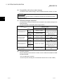
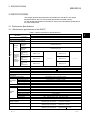
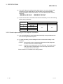
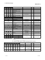
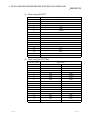
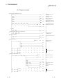
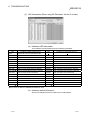
3.1.2 Usable temperature sensor types, measurement temperature ranges and data
resolutions
(1) For use of Q64TCTT(BW)
Table 3.2 Thermocouple type, measurement temperature range and data resolution list
Thermocouple
type
R
°C
Measurement
temperature range
0 to 1700
°F
Data resolution
1
0 to 500
0 to 800
1
0 to 1300
K
Measurement
temperature range
0 to 3000
0 to 1000
0 to 2400
Data resolution
1
1
-200.0 to 400.0
0.0 to 400.0
0.0 to 500.0
0.1
0.0 to 1000.0
0.1
0.0 to 800.0
0 to 500
0 to 800
J
0 to 1000
1
0 to 1200
0 to 1600
1
0 to 2100
0.0 to 400.0
0.0 to 500.0
0.1
0.0 to 1000.0
0.1
0.0 to 800.0
-200 to 400
-200 to 200
T
0 to 200
0 to 700
-300 to 400
1
0 to 400
-200.0 to 400.0
0.0 to 400.0
0.1
0.0 to 700.0
0.1
S
0 to 1700
1
0 to 3000
1
B
0 to 1800
1
0 to 3000
1
1
0 to 1800
1
0.0 to 700.0
0.1
———
———
N
0 to 1300
1
0 to 2300
1
U
-200 to 200
0 to 400
E
0 to 1000
0 to 400
0.0 to 600.0
0 to 400
L
0 to 900
0.0 to 400.0
0.0 to 900.0
3-3
1
1
0.1
1
0 to 700
-300 to 400
———
0 to 800
0 to 1600
1
———
1
0.1
———
———
PL II
0 to 1200
1
0 to 2300
1
W5Re/W26Re
0 to 2300
1
0 to 3000
1
3-3
3 SPECIFICATIONS
MELSEC-Q
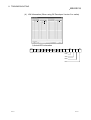
(2) For use of Q64TCRT(BW)
Table 3.3 Usable platinum temperature-measuring resistors, measurement
temperature ranges and data resolutions
°C
Platinum
temperaturemeasuring resistor
Pt100
JPt100
Measurement
temperature range
°F
Data resolution
-200.0 to 600.0
0.1
-200.0 to 200.0
-200.0 to 500.0
0.1
-200.0 to 200.0
Measurement
temperature range
Data resolution
-300 to 1100
1
-300.0 to 300.0
0.1
-300 to 900
1
-300.0 to 300.0
0.1
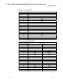
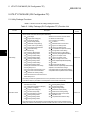
3.2 Function Summary
The Q64TC function summary is shown in Table 3.3.
Table 3.3 Q64TC function summary
Item
Specification
Auto-tuning function
• The temperature control module automatically sets the optimal PID constants.
Forward action/reverse action
• Heat control (reverse action) or cooling control (forward action) can be selected and
selection function
controlled.
RFB limiter function
Sensor compensation function
Unused channel setting
• Limit the manipulation value overshoot which frequently occurs when the set value (SV)
is changed or control target is changed.
• Reduces the difference between the measured value and actual temperature to zero
when these two are different due to measurement conditions, etc.
• Sets the PID operation for channels that do not perform temperature adjustment to "not
execute."
PID control forced stop
• Stops the PID operation for channels that is performing temperature adjustment.
Heater disconnection detection
• Measures the current that flows in the heater main circuit and detects disconnection
function
when Q64TCTTBW or the Q64TCRTBW is used.
Current error detection function
when output is off
Loop disconnection detection
function
2
current in the heater's main circuit while the transistor's output is off, and checks if there
disconnection, abnormal external operation device (such as magnet relay), or a
can be reduced.
• This function continues/stops temperature adjustment control output at CPU stop error
3-4
3.2.4
3.2.5
3.2.6
3.2.7
3.2.8
3.2.9
2
• By backing up the buffer memory contents to E PROM, the load of sequence program
• Monitors the process value (PV) and alerts the user.
Online module change
3.2.3
• A function to detect errors in the control system (control loop) caused by a load (heater)
Control output setting for CPU
Q64TC control status
3.2.2
is a current error when output is off.
Alert alarm
stop error occurrence
3.2.1
• When the Q64TCTTBW or the Q64TCRTBW is used, this function measures the
thermocouple disconnection.
Data storage in E PROM
Reference
occurrence.
• The Q64TC can be controlled by the output signal of Q64TC and the settings in the
buffer memory.
• A module change is made without the system being stopped.
3.2.10
3.2.11
3.2.12
3.2.13
Chapter 7
3-4
3 SPECIFICATIONS
MELSEC-Q
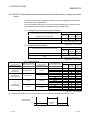
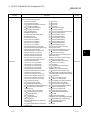
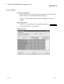
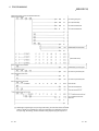
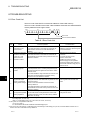
3.2.1 Auto tuning function
(1) What is the auto tuning function?
(a) The auto tuning function is designed for the Q64TC to set the optimum PID
constants automatically.
In auto tuning, the PID constants are calculated according to the hunting
cycle and amplitude which take place when a manipulated value turned on/off
alternates between overshooting and undershooting a set value.
(b) Setting the following data enables auto tuning to be executed. Note that since
actual control starts on completion of auto tuning, the other data should be
preset to the values used for actual operation.
When "0" has been set to the proportional band (P), auto tuning is not
executed.
Buffer memory address name
Input range
Set value (SV) setting
Upper output limiter
Lower output limiter
Output variation limiter
Sensor compensation value
setting
Control output period setting
Primary delay digital filter setting
AUTO/MAN mode switching
AT bias
Forward/reverse action setting
Auto tuning mode selection
CH1
20H
22H
2AH
2BH
2CH
Addresses (Hexadecimal)
CH2
CH3
40H
60H
42H
62H
4AH
6AH
4BH
6BH
4CH
6CH
CH4
80H
82H
8AH
8BH
8CH
2DH
4DH
6DH
8DH
2FH
30H
32H
35H
36H
B8H
4FH
50H
52H
55H
56H
B9H
6FH
70H
72H
75H
76H
BAH
8FH
90H
92H
95H
96H
BBH
(c) On completion of auto tuning, calculated values are set to the following buffer
memory addresses.
Buffer memory address name
Addresses (Hexadecimal)
CH2
CH3
43H
63H
44H
64H
45H
65H
CH4
Proportional band (P) setting
83H
Integral time (I) setting
84H
Derivative time (D) setting
85H
Loop disconnection detection
3BH
5BH
7BH
9BH
judgment time
: As the loop disconnection detection judgment time, a value twice greater than the
calculated integral time is set. However, the loop disconnection detection
judgment time remains unchanged from 0 when it is 0 at an auto tuning start.
3-5
CH1
23H
24H
25H
3-5
3 SPECIFICATIONS
MELSEC-Q
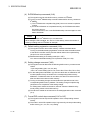
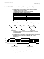
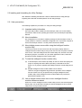
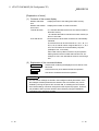
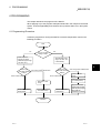
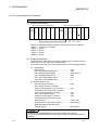
(2) Executing auto-tuning
(a)
Conditions for starting auto-tuning
When any of the following conditions is met, auto-tuning is not executable.
1) The module is in the setting mode (Xn1: OFF).
2) In the proportional section setting (buffer memory address: 23H, 43H,
63H, 83H), 0 is set. (2-position control)
3) In the AUTO/MAN setting (buffer memory address: 32H, 52H, 72H,
92H), 1 (Manual) is set.
4) In the Unused channel setting (buffer memory address: 3DH, 5DH,
7DH, 9DH), 1 (Unused) is set for the channel.
5) The PID control forced stop command (YnC to YnF) is ON.
6) Hardware failure is identified. (The ERR. LED turns ON.)
7) The measured temperature value (PV) (buffer memory address: 9H to
CH) exceeds the measured temperature range (Refer to Section
3.5.4).
For conditions 1) to 5), auto-tuning starts as soon as the condition is
changed.
For condition 6) and 7), the auto-tuning status flag (Xn4 to Xn7) turns on
momentarily. Auto-tuning does not start until the auto-tuning status flag
(Xn4 to Xn7) turns on again (OFF to ON) even if the condition is changed.
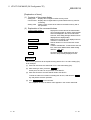
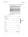
(b)
Auto tuning is performed in the following procedure.
Q64TC data setting
Set to the buffer memory addresses
indicated in (1), (b).
Operation mode setting
Turn on the setting/operation mode
command (Yn1).
Confirm that the setting/operation
mode status (Xn1) is on.
Auto tuning start
Turn on the auto tuning command
(Yn4, Yn5, Yn6, Yn7).
Auto tuning in progress
The auto tuning status flag
(Xn4, Xn5, Xn6, Xn7) turns on.
Auto tuning completion
(PID constants set)
The auto tuning executing flag
(Xn4, Xn5, Xn6, Xn7) turns off and
the calculated values are set to
the buffer memory addresses
indicated in (1), (c).
Temperature control using
PID constants set
POINT
After powering off the PLC CPU, you can use the set PID constants in the following
method.
• Write the values directly to the buffer memory using the sequence program.
2
• Store the PID constants into E PROM and transfer them when powering on the
PLC CPU.
• Use the initial settings of the GX Configurator-TC.
3-6
3-6
3 SPECIFICATIONS
MELSEC-Q
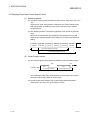
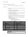
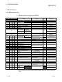
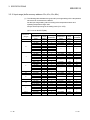
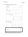
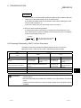
(c)
Auto tuning operation
Auto tuning performs operation as shown below.
1) Auto tuning output is provided.
2) Data collection starts when the process value returns to the set value
after the first overshoot and undershoot.
3) After data collection, auto tuning ends when PID constants and loop
disconnection detection judgment time are set.
Process value (PV)
The first overshoot and
undershoot are ignored.
End of auto tuning
Set value (SV)
(Temperature set value)
Start of auto tuning
Time
Data collection
Temperature
control
Auto tuning in execution
ON
Yn4,Yn5,Yn6,Yn7
OFF
ON
Xn4,Xn5,Xn6,Xn7
OFF
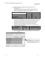
(d)
Precautions for auto tuning
The following indicate the conditions under which auto tuning will result in
abnormal termination.
1) The setting/operation mode command (Yn1) has been turned OFF.
(Except for the case where the PID continue flag (buffer memory
address: A9H) is "Continue".)
2) Any of the following setting items for the channel has been changed
during execution of auto-tuning.
Setting item
CH2
CH3
CH4
Set value (SV) setting
22H
42H
62H
82H
Upper output limiter
2AH
4AH
6AH
8AH
Lower output limiter
2BH
4BH
6BH
8BH
Sensor compensation value setting
2DH
4DH
6DH
8DH
Primary delay digital filter setting
30H
50H
70H
90H
AUTO/MAN mode switch
32H
52H
72H
92H
AT bias
35H
55H
75H
95H
Forward/reverse operation setting
36H
56H
76H
96H
Unused channel setting
3DH
5DH
7DH
9DH
3)
3-7
Buffer memory address (Hexadecimal)
CH1
The measured temperature value (PV) (buffer memory address: 9H to
C H) exceeds the measured temperature range (refer to section 3.5.4).
3-7
3 SPECIFICATIONS
MELSEC-Q
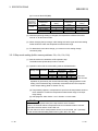
4)
5)
6)
7)
8)
9)
The following time exceeds 2 hours.
• Time elapsed from the auto-tuning start until the set value is reached
at the first time.
• A half of the hunting cycle
The value calculated by PID constants after auto-tuning exceeds any
of the following ranges.
Proportional section (P): 0.1 to 1000.0 (%)
Integral time (I): 1 to 3600 (s)
Derivative time (D): 0 to 3600 (s)
The PID control forced stop command (YnC to YnF) has been turned
ON.
Hardware failure has occurred.
The proportional section (P) setting (buffer memory address: 23H, 43H,
63H, 83H) has been changed to 0. (2-position control)
The upper setting limiter (buffer memory address: 37H, 57H, 77H, 97H)
or the lower setting limiter (buffer memory address: 38H, 58H, 78H, 98H)
has been changed and thereby the set value (SV) is outside the
setting range.
(3) Operation at termination of auto tuning
(a) Operation at normal termination
• The auto tuning status flag (Xn4 to Xn7) turns off.
• The PID constants are set.
• The loop disconnection detection judgment time (buffer memory addresses:
3BH, 5BH, 7BH, 9BH) is set. (If the loop disconnection detection judgment
time is 0 at the start of auto tuning, it remains unchanged from 0.)
(b) Operation at abnormal termination
• The auto tuning status flag (Xn4 to Xn7) turns off.
• The PID constants are not set.
(4) Adjustment after auto tuning
(a) Specific readjustment is not needed for the PID constants calculated by auto
tuning.
(b) Use the control response parameters (buffer memory addresses: 31H, 51H,
71H, 91H) to change the control response for the PID constants calculated by
auto tuning.
REMARK
1) The time between the start and completion of auto tuning depends on the object
to be controlled.
2) You can confirm that auto tuning has been completed by checking that the auto
tuning status flag (Xn4, Xn5, Xn6, Xn7) has turned from on to off.
3) When the automatic backup setting (3FH, 5FH, 7FH, 9FH) is preset at an auto
tuning start to be made valid after auto tuning of the PID constants, the PID
constants and loop disconnection detection judgment time are automatically
2
backed up by E PROM on completion of auto tuning.
3-8
3-8
3 SPECIFICATIONS
MELSEC-Q
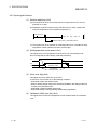
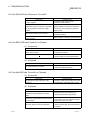
3.2.2 Reverse/Forward action select function
With the Q64TC, "reverse action" or "forward action" can be selected to perform the
PID operations.
(1) Q64TC default
The default is set at "reverse action" for Q64TC.
When performing the PID operations with the "forward action," set to the forward
action in the reverse/forward action selection buffer memory(36H,56H,76H, and
96H).
(2) Reverse/forward action control details
(a) Reverse action : Used for heating control to increase temperature.
(b) Forward action : Used for cooling control to decrease temperature.
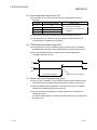
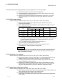
3.2.3 RFB limiter function
(1) RFB(Reset feed back) limiter function
The RFB limiter function limits the PID operation result (manipulated value : MV)
not to exceed the valid range by the integral control action when an error
continues for a long time.
With the RFB limiter function, if the PID operation result exceeds the upper/lower
output limiter value, the amount exceeded is fed back to the integral value and
the PID operation result is kept at the limit value.
3.2.4 Sensor compensation function
(1) Sensor compensation function
The sensor compensation function compensates the difference between the
measured temperature and actual temperature caused by measurement
conditions.
(2) Sensor compensation value setting
When there is a difference between the measured temperature and actual
temperature, the full-scale percentage (-50.00 to 50.00%) is set in the buffer
memory for sensor compensation value setting (2DH, 4DH, 6DH and 8DH) as the
sensor compensation value.
For example, when the input range is at -200°C to 200°C and there is a 2°C
error, the full-scale is 400°C(200°C-(-200°C)=400°C).
Therefore, 2/400 x 100 = 0.5% is set.("50" is set in the buffer memory.)
3-9
3-9
3 SPECIFICATIONS
MELSEC-Q
3.2.5 Unused channel setting
(1) Channels where temperature sensors are not connected
The Q64TC performs upscale processing on the channels where temperature
sensors (thermocouples/platinum temperature-measuring resistors) are not
connected.
Hence, when a temperature sensor is not connected to the channel which will not
exercise temperature control, the PV value is judged as higher than the
temperature measurement range of the input range, and the "ALM" LED is lit by
alert processing.
(2) Unused channel setting
(a) To make unused channel setting, write "1" to the unused channel setting
buffer memory.
(b) After the unused channel setting has been made, no alert will occur at the
channel with no temperature sensor connected and the "ALM" LED will not
be lit.
The sampling period remains unchanged if the unused channel setting is
performed.
3.2.6 Forced PID control stop
(1) Forced PID control stop
Forced PID control stop is a function to stop PID operations temporarily from the
PLC CPU.
The action to be taken by the Q64TC at a PID operation stop depends on the
setting of the stop mode setting buffer memory (21H, 41H, 61H, 81H).
(2) Executing forced PID control stop
To execute a forced PID control stop, turn on the forced PID control stop
command (YnC to YnF).
At this time, the manipulated value storage buffer memory (DH to 10H) value is 50 (-5.0%).
(3) Canceling forced PID control stop
When the forced PID control stop command is turned off, a forced PID control
stop is canceled and PID operations are resumed at the manipulated value which
was output during the forced PID control stop.
POINT
Setting the PLC CPU to the STOP status turns off the forced PID control stop
command, "canceling the forced PID control stop".
3 - 10
3 - 10
3 SPECIFICATIONS
MELSEC-Q
3.2.7 Heater disconnection detection function (supported only by Q64TCTTBW,
Q64TCRTBW)
(1) Heater disconnection detection function
(a) This is a function to check if there is a heater wire breakage using the
standard heater current value (load current value detected by the current
sensor (CT)), when the transistor output is on.
(b) The heater disconnection detection function compares the current values of
standard heater and heater disconnection alert, and determines that there is a
heater wire breakage when the current value of standard heater is below that
of heater disconnection alert.
However, when the transistor turned-on time is less than 0.5 seconds, the
heater disconnection detection is not performed.
(2) Heater disconnection compensation function
(a) Heater disconnection compensation
When the heater voltage drops, the heater current decreases as well.
The Q64TCTTBW, Q64TCRTBW heater disconnection detection measures
the heater current and determines the heater disconnection.
Therefore, when the heater voltage drops, there are possibilities that a false
alarm may be set due to the voltage change.
Therefore, the Q64TCTTBW, Q64TCRTBW compensates for a drop in heater
current (heater breakage compensation) so that the drop in heater current
does not activate the break detection.
(b) Heater disconnection compensation method
The heater disconnection compensation calculates "the heater current for
each channel" - "standard current," and the largest positive value is set as the
compensation value.
When there is no positive values, the value with the smallest negative value is
used as the compensation value.
The heater current for each channel is compensated with the compensation
value and a heater disconnection is detected when the compensated value
exceeds the specified heater disconnection detection setting value.
Example 1: When the difference from the standard current at each channel is:
Channel 1: -2%, Channel 2: 5%, Channel 3: -1%, Channel 4: -17%, the
compensation value becomes 5%.
The heater disconnection detection is performed from the values after a 5%
compensation: Channel 1: -7%, Channel 2: 0%, Channel 3: -6%, Channel 4: 22%.
Thus, when the heater disconnection detection setting value is at 80%, only
channel 4 is detected as disconnected.
Heater
disconnection Difference from the Compensation
Channel No.
value
detection setting standard current
value
Disconnected
No
1
-2%
-7%
2
5%
0%
No
-6%
No
-22%
Yes
3
4
3 - 11
Difference from the
standard current
after compensation
80%
-1%
-17%
5%
3 - 11
3 SPECIFICATIONS
MELSEC-Q
Example 2: The difference from the standard current at each station is: Channel
1: -16%, Channel 2: -17%, Channel 3: -22%, Channel 4: -19%, the compensation
value becomes -16%.
The heater disconnection detection is performed from the values after a -16%
compensation: Channel 1: 0%, Channel 2: -1%, Channel 3: -6%, Channel 4: -3%.
Thus, when the heater disconnection detection setting value is at 80%, none of
the channels are detected as disconnected.
Heater
disconnection Difference from the Compensation
Channel No.
detection setting standard current
value
value
1
-16%
2
-17%
80%
-16%
3
-22%
4
-19%
Difference from the
standard current
after compensation
Disconnected
0
-1%
-6%
-3%
No
No
No
No
(c) Restrictions
• The heater-disconnection compensation function will not work if only one
channel is used.
• The heater-disconnection compensation function will not work if only one
channel is used to keep the heater on while the others are used to keep it
off.
The module may detect a disconnection even when the heater is not
disconnected.
• The heater disconnection detection compensation value is up to 20%.
Therefore, when there is a voltage drop by more than 40%, a disconnection
is detected even with a 20% compensation.
3.2.8 Output off-time current error detection function (available for Q64TCTTBW and
Q64TCRTBW only)
(1) Using the reference heater current value (load current value detected by the
current sensor (CT)), this function checks for a transistor output off-time current
error when the transistor output is off.
(2) The transistor output off-time current error detection function compares the
reference heater current value and the current value of the heater disconnection
alert, and judges it as an output off-time current error if the reference heater current
value is higher than the current value of the output off-time current alert.
Note that output off-time current error detection will not be made if the transistor
output off period is within 0.5 seconds.
3.2.9 Loop disconnection detection function
The loop disconnection detection function detects errors in the control system (control
loop) caused by a load (heater) disconnection, external operation device (e.g.
magnetic relay) fault, input disconnection and others.
When the PID operation value has reached 100% or 0%, this function starts monitoring
the variation of the process value per loop disconnection detection judgment time to
detect a heater or input disconnection.
(1) When the heater is disconnected, when the input is disconnected or shorted, or
when the external operation device contact does not turn on, it is judged as an
error since the temperature will not rise despite the control output provided.
In this case, an alert is output if a temperature rise of 2°C or more is not observed
within the preset loop disconnection detection judgment time after the control
output is provided 100%.
3 - 12
3 - 12
3 SPECIFICATIONS
MELSEC-Q
(2) When the input is disconnected or when the external operation device contact is
welded, it is judged as an error since the temperature will rise though the control
output is not provided.
In this case, an alert is output if a temperature fall of 2°C or more is not observed
within the preset loop disconnection detection judgment time after the control
output has dropped to 0%.
(In either case, inverse operation will be performed for forward action: cooling
control.)
POINT
(1) When not using the loop disconnection detection function, set the loop
disconnection detection judgment time to "0".
(2) Setting the loop disconnection detection dead band will not cause a loop
disconnection if there is no temperature variation of 2°C or more when the
control output is provided 100% or 0% at the set value. (Refer to Section
3.5.32.)
2
3.2.10 Data storage on E PROM
2
(1) Data storage on E PROM
2
(a) The Q64TC buffer memory data can be stored onto E PROM for backup.
The whole write-enabled area of the buffer memory can be backed up. Refer
to Section 3.5 for details of the buffer memory.
Buffer memory backed-up addresses (Hexadecimal)
20H to 38H
40H to 58H
60H to 78H
80H to 98H
3AH to 3DH
4AH to 5DH
6AH to 7DH
8AH to 9DH
Remarks
A4H to AAH
—————
AFH
B0H
B5H
C0H to C3H
D0H to D3H
E0H to E3H
F0H to F3H
Q64TCTTBW,
108H to 11FH
Q64TCRTBW only
2
Write to E PROM can be used to back up the PID constants set by auto
tuning and the data written directly to the buffer memory using a peripheral
device.
2
Write to E PROM eliminates the program used to set data to the Q64TC.
2
(b) The backed up data is transferred from E PROM to buffer memory when the
PLC CPU is powered on (power is switched on) or reset.
Hence, temperature control can be exercised without data being written when
the PLC CPU is powered on or reset.
3 - 13
3 - 13
3 SPECIFICATIONS
MELSEC-Q
2
(2) Writing data to E PROM
2
2
(a) When writing data to E PROM, turn on the E PROM backup command
(Yn8).
2
• The E PROM write completion flag (Xn8) turns on at completion of data
2
write to E PROM.
2
2
• The E PROM write failure flag (XnA) turns on if write of data to E PROM is
not completed normally.
2
(b) Make changes to buffer memory when the E PROM write completion flag is
off.
Q64TC
PLC CPU
1) Yn8 : ON
(Write command)
3) Xn8 : ON
(completed)
OS
E2PROM
2) Write
Buffer
memory
data
Read
At power-on
or reset
2
(3) Reading data from E PROM
2
E PROM data read occurs under either of the following conditions.
• When the PLC CPU is powered on or reset.
2
• When the E PROM's PID constant read command (3EH, 5EH, 7EH, 9EH) turns
on. Note that the read data are only the PID constants and loop disconnection
detection judgment time of the corresponding channel.
3 - 14
3 - 14
3 SPECIFICATIONS
MELSEC-Q
3.2.11 Alert alarms
(1) The alert alarm is a function which sets the system in an alert status when the
process value (PV) or deviation reaches the alert set value. It is used to turn on
the device's hazard signal or operate the safety device.
The alert alarm is classified as follows:
• Input alerts ............. Upper limit input alert, lower limit input alert
• Deviation alerts...... Upper limit deviation alert, lower limit deviation alert,
upper/lower limit deviation alert, within-range alert
(a) Input alerts
1) Upper limit input alert
When the process value (PV) is equal to or greater
than the alert set value, the system is put in an alert
status.
Process value (PV)
Process value (PV)
2) Lower limit input alert
When the process value (PV) is equal to or less
than the alert set value, the system is put in an
alert status.
Process value (PV)
Process value (PV)
Alert set value
Alert set value
Time
Time
Alert status
Alert status
Non-alert status
Alert status
(b) Deviation alerts
1) Upper limit deviation alert
When the deviation [process value (PV) - set value (SV)] is equal to or
greater than the alert set value, the system is put in an alert status.
[When alert set value is negative]
[When alert set value is positive]
Process value (PV)
Process value (PV)
Process value (PV)
Alert set value
Temperature
set value (SV)
Temperature
set value (SV)
Alert set value
Process value (PV)
Time
Alert status
Time
Alert status
Non-alert status
3 - 15
Alert status
3 - 15
3 SPECIFICATIONS
MELSEC-Q
2) Lower limit deviation alert
When the deviation [process value (PV) - set value (SV)] is equal to or less
than the alert set value, the system is put in an alert status.
[When alert set value is negative]
[When alert set value is positive]
Process value (PV)
Process value (PV)
Process value (PV)
Alert set value
Temperature
set value (SV)
Temperature
set value (SV)
Alert set value
Process value (PV)
Time
Time
Alert status
Alert status
Non-alert status
Alert status
3) Upper/lower limit deviation alert
When the deviation [process value (PV) - set value (SV)] is equal to or
greater than the alert set value, the system is put in an alert status.
Process value (PV)
Process value (PV)
Alert set value
Temperature
set value (SV)
Alert set value
Time
Alert status
Non-alert status
Alert status
4) Within-range alert
When the deviation [process value (PV) - set value (SV)] is equal to or less
than the alert set value, the system is put in an alert status.
Process value (PV)
Process value (PV)
Alert set value
Temperature
set value (SV)
Alert set value
Time
Alert status
3 - 16
Non-alert status
Alert status
3 - 16
3 SPECIFICATIONS
MELSEC-Q
(2) The Q64TC allows the alert alarm in (1) to be set with the addition of an alert dead
band, alert delay count or wait/re-wait.
The following table indicates the alert alarms which can be used with the addition
of alert dead band, alert delay count and wait/re-wait.
Alert alarm
Upper limit alert
Input alert
Lower limit alert
Upper limit
deviation alert
Lower limit
Deviation
deviation alert
alert
Upper/lower limit
deviation alert
Within-range alert
Dead band setting
Alert delay count
Wait
Re-wait
——
——
——
——
(a) Alert dead band setting
When the process value (PV)/deviation is close to the alert set value, the alert
status may alternate with the non-alert status due to input instability or the like.
Setting the alert dead band prevents the alert status and non-alert status from
alternating with each other due to input instability or the like when the process
value (PV)/deviation is near the alert set value.
Example: When the dead band value is set to the upper limit input alert, the
system is placed in the alert status when the upper limit of the input
rises to or above the alert set value. The system is put in the nonalert status when the upper limit falls below the alert dead band.
[When alert dead band value is set]
[When alert dead band value is not set]
Process value (PV)
Process value (PV)
Process value (PV)
Process value (PV)
Alert set value
Alert set value
Dead band
Time
Time
Alert status
Alert status
Non-alert status
Alert status
(b) Alert delay count setting
The system is set in the alert status when the process value (PV) that has
reached the alert set value remains in the alert range until the sampling count
becomes equal to or greater than the preset number of alert delays.
Example: When the number of alert delays set to the input upper limit alert is
5, the system is not placed in the alert status if the sampling count
is 4 or less.
Process value (PV)
Process value (PV)
Alert set value
Temperature set value (SV)
Time
Input sampling
3 times
5 times
Alert status
3 - 17
3 - 17
3 SPECIFICATIONS
MELSEC-Q
(c) Wait alert
Choosing the wait alert ignores the alert status if the process value
(PV)/deviation is in that status when the setting mode is changed to the
operation mode, and makes the alert function invalid until the process value
comes out of the alert status once.
Example: Selecting the lower limit deviation alert with wait makes the alert
function invalid until the process value exceeds the alert set value.
[Lower deviation alert with wait]
[Lower deviation alert]
Process value (PV)
Process value (PV)
Process value (PV)
Temperature
set value (SV)
Process value (PV)
Temperature
set value (SV)
Alert set value
Alert set value
Time
Time
Alert status
Wait operation region
Non-alert status
Alert status
Alert status
POINT
When the system has reached the non-alert status even once after an alert
judgment start following the setting of the alert mode, the alert function with wait will
be invalid if you choose the mode with wait.
(d) Re-wait alert
The re-wait alert is a wait alert-based feature which has the additional
function to make the alert function invalid again when the set value (SV) is
changed.
For set value changing control, choosing the re-wait alert avoids the alarm
status reached when the set value is changed.
Example: If the process value (PV) is at the position as shown below before
the setting is changed, changing the temperature set value (SV) for
deviation alert will put the process value in the alert region and turn
on the alert. To prevent this, the function makes the alert wait
operation valid and the alert output to wait.
Process value (PV)
Before temperature
set value (SV) change
Alert region
Alert set value
Temperature set value (SV)
Process value (PV)
After temperature
set value (SV) change
Alert region
Alert set value
3 - 18
Temperature
set value (SV) change
Temperature set value (SV)
3 - 18
3 SPECIFICATIONS
MELSEC-Q
(3) The Q64TC allows four different alerts (alert alarms 1 to 4) to be selected and
used from among the alert alarms, wait alert alarm and re-wait alert alarm.
Set the alert alarms used as alert alarms 1 to 4 at the following buffer memory
addresses:
• Alert alarm 1: C0H to C3H
• Alert alarm 3: E0H to E3H
• Alert alarm 2: D0H to D3H
• Alert alarm 4: F0H to F3H
(4) Set the alert set value, alert dead band value and alert delay count at the following
buffer memory addresses:
Channel No.
Buffer memory addresses
Alert set value
1
26H to 29H
2
46H to 49H
3
66H to 69H
4
86H to 89H
Alert dead band value
Alert delay count
A4H
A5H
3.2.12 Control output setting at CPU stop error occurrence
(1) You can set the Q64TC control output (HOLD/CLEAR) to be provided when the
PLC CPU has generated a stop error.
(2) To make this setting, use the intelligent function module switch setting on GX
Developer.
• CLEAR : Stops the PID control, temperature judgement and alert judgement
functions and turns off external outputs.
• HOLD : Holds the control status prior to a PLC CPU stop. For example, when
PID control was exercised before a PLC CPU stop, PID control is
continued if the PLC CPU stops.
Refer to Section 4.5 for details of the setting method.
3 - 19
3 - 19
3 SPECIFICATIONS
MELSEC-Q
3.2.13 Q64TC control status controlling output signal and buffer memory settings and control
status
The Q64TC has the output signals (Y), buffer memory and intelligent function module
switch which set its control status.
The control status of the Q64TC is governed as indicated below by the settings of the
output signals, buffer memory and intelligent function module switch.
(1) Intelligent function module switch setting
Control status
Output setting for CPU stop error (refer to Section 4.5)
PID control
Intelligent function module switch
If a CPU stop error occurs at the setting of "CLEAR"
—
Temperature
Alert
judgment
judgment
—
—
In accordance with control
Other than above
status of other setting items
: Executed, —: Not executed
(2) Unused channel setting
Control status
Unused channel setting (refer to Section 3.5.33)
PID control
3DH, 5DH, 7DH, 9DH
Unused
—
Temperature
Alert
judgment
judgment
—
—
In accordance with control
Used
status of other setting items
: Executed, —: Not executed
(3) Other settings
Setting/operation
mode command
(refer to Section 3.4)
Yn1, Xn1
1)
Setting mode
(at power-on)
2)
Operation mode
(during operation)
A9H
Forced PID control
stop command
(refer to Section 3.4.3)
YnC to YnF
Stop/continue
OFF/ON
PID continuation flag
(refer to Section 3.5.41)
OFF
Stop/continue
Stop
3)
Setting mode
(after operation)
ON
OFF/ON
OFF
Continue
ON
Stop mode setting
(refer to Section 3.5.13)
21H, 41H, 61H, 81H
Stop
Monitor
Alert
Stop/monitor/alert
Stop
Monitor
Alert
Stop
Monitor
Alert
Stop/monitor/alert
Stop
Monitor
Alert
Control status
Temperature
judgment
Alert
judgment
—
—
—
—
—
—
—
—
—
—
—
—
—
—
—
—
—
—
—
—
—
—
—
—
PID control
: Executed, —: Not executed
: The settings of the setting/operation mode command will be explained in the following three different modes.
ON
Setting/operation
mode command
OFF
3 - 20
1) Setting mode
2) Operation
mode
3) Setting mode
3 - 20
3 SPECIFICATIONS
MELSEC-Q
3.3 Sampling Period and Control Output Period
(1) Sampling period
(a) The Q64TC performs PID operations in order of CH1, CH2, CH3, CH4, CH1,
CH2 .....
The time from when PID operation is started on the current channel (CHn)
until PID operation is restarted on the current channel (CHn) is called a
sampling period.
(b) The sampling period is 0.5 seconds regardless of the number of channels
used.
Since error check and other processings are also performed on unused
channels, the sampling period will not change if you make unused channel
setting.
CH1 PID
operation
CH2 PID
operation
CH3 PID
operation
CH4 PID
operation
CH1 PID
operation
CH2 PID
operation
0.5 seconds (sampling period)
0.5 seconds (sampling period)
(2) Control output period
(a) The control output period indicates the ON/OFF cycle of transistor output.
OFF
ON
OFF
ON
Transistor output
Control output period
Control output period
The manipulated value (MV) represents the ON time of this control output
period as a percentage. (Refer to Section 3.5.6)
(b) Set the control output period to the control output period setting buffer
memory (2FH, 4FH, 6FH, 8FH) in the range 1 to 100s.
3 - 21
3 - 21
3 SPECIFICATIONS
MELSEC-Q
3.4 I/O Signals Transferred to/from the PLC CPU
This section explains the allocation and applications of the Q64TC I/O signals.
3.4.1 I/O signal list
(1) The Q64TC uses 16 input points and 16 output points to transfer signals to/from
the PLC CPU.
(2) Table 3.4 lists the I/O signals used by the Q64TC.
Inputs (X) mean the signals from the Q64TC to the PLC CPU and outputs (Y) the
signals from the PLC CPU to the Q64TC.
(3) The I/O signals (X, Y) indicated in this manual assume that the module is loaded
on the I/O slot 0 of the main base unit.
If the Q64TC is mounted on other than the I/O slot 0, change the I/O signals for
those of the slot where the module is mounted.
(4) When the Q64TCTTBW or Q64TCRTBW is used, the device numbers of the I/O
signals increase by 16 points depending on how many free points the left-hand
side slots have.
Hence, as I/O signals are given as indicated below in this manual, read them
according to the module used.
Example) When a signal is given as Yn1
When Q64TCTT or Q64TCRT is used: Y1
When Q64TCTTBW or Q64TCRTBW is used: Y11
Table 3.4 I/O signal list
Input signal (Signal direction: Q64TC PLC CPU)
Device No.
Signal name
Xn0
Module ready flag
Xn1
Setting/operation mode status
Xn2
Write error flag
Xn3
Hardware error flag
Xn4
CH1 auto tuning status
Xn5
CH2 auto tuning status
Xn6
CH3 auto tuning status
Xn7
CH4 auto tuning status
2
Xn8
E PROM write completion flag
Xn9
Default value write completion flag
2
XnA
E PROM write failure flag
XnB
Setting change completion flag
XnC
CH1 alert occurrence flag
XnD
CH2 alert occurrence flag
XnE
CH3 alert occurrence flag
XnF
CH4 alert occurrence flag
Output signal (Signal direction: Q64TC PLC CPU)
Device No.
Signal name
Yn0
Reserved
Yn1
Setting/operation mode command
Yn2
Error reset command
Yn3
Reserved
Yn4
CH1 auto tuning command
Yn5
CH2 auto tuning command
Yn6
CH3 auto tuning command
Yn7
CH4 auto tuning command
2
Yn8
E PROM backup command
Yn9
Default setting registration command
YnA
Reserved
YnB
Setting change command
YnC
CH1 forced PID control stop command
YnD
CH2 forced PID control stop command
YnE
CH3 forced PID control stop command
YnF
CH4 forced PID control stop command
POINT
We cannot guarantee the functions of the Q64TC if any of the reserved areas is
turned on/off in a sequence program.
3 - 22
3 - 22
3 SPECIFICATIONS
MELSEC-Q
3.4.2 Input signal functions
(1) Module ready flag (Xn0)
(a) This signal turns on as soon as the Q64TC is ready when the PLC CPU is
powered on or reset.
(b) Read/write of Q64TC buffer memory data from the PLC CPU is performed
when the temperature control module ready flag is on.
Write command
X1
TOP H0
H22
K100
K1
Used as buffer memory read/write interlock.
(c) This signal turns off on detection of a watchdog timer error. The Q64TC stops
temperature control operation and turns off the output.
(2) Setting/operation mode status (Xn1)
This signal turns on in the operation mode and turns off in the setting mode.
Do not change the set value during mode shift processing.
Yn1
Xn1
Setting mode
Operation mode
Setting mode
During mode
shift processing
(3) Write error flag (Xn2)
This signal turns on at write error occurrence.
A write error occurs under any of the following conditions.
• When data is set to the reserved area.
• When a setting change made to the area write-enabled in the setting mode only
is made in the operation mode.
• When data outside the setting range is set.
• When data setting is changed during default setting registration.
(4) Hardware (H/W) error flag (Xn3)
This signal turns on when the temperature control module results in a hardware
error.
3 - 23
3 - 23
3 SPECIFICATIONS
MELSEC-Q
(5) Auto tuning status flag (Xn4 to Xn7)
(a) This signal turns on when auto tuning of the corresponding channel is
executed.
Channel
Auto tuning status flag
1
Xn4
2
Xn5
3
Xn6
4
Xn7
ON/OFF status
ON : Auto tuning in execution
OFF: Auto tuning not in execution or
completed
(b) Auto tuning is executed using the auto tuning command (Yn4 to Yn7).
(c) This signal turns "on" while auto tuning is being executed and turns "off"
automatically on completion of auto tuning.
2
(6) E PROM write completion flag (Xn8)
(a) This signal turns on after completion of write of buffer memory contents to
2
2
E PROM which starts when the E PROM backup command (Yn8) turns on.
2
2
(b) When the E PROM backup command turns off, the E PROM write
completion flag also turns off.
ON
Yn8
OFF
ON
Xn8
XnA
OFF
OFF
During write to E2 PROM
2
Completion of write to E PROM
(7) Default value write completion flag (Xn9)
(a) Turns on after completion of write of Q64TC default values to buffer memory
which starts when the default setting registration command (Yn9) turns on.
(b) When the default setting registration command (Yn9) turns off, the default
value write completion flag (Xn9) also turns off.
(c) Perform unused channel setting to unused channels after completion of
default value write.
If unused channel setting is not made to unused channels, the "ALM" LED of
the Q64TC is lit.
3 - 24
3 - 24
3 SPECIFICATIONS
MELSEC-Q
2
(8) E PROM write failure flag (XnA)
2
(a) This signal turns on at a failure of write of buffer memory contents to E PROM
2
which starts when the E PROM backup command (Yn8) turns on.
2
• OFF : Completion of write to E PROM
2
• ON : Failure of write to E PROM (Write could not be completed normally)
ON
Yn8 OFF
ON
Xn8 OFF
XnA OFF
During write
2
to E PROM
2
Error detection of write to E PROM
2
(b) The E PROM write failure flag turns off at normal completion of write to
2
E PROM.
2
2
(c) When the E PROM write failure flag has turned on, the E PROM contents
are undefined.
2
Hence, powering on the PLC CPU again or resetting it with the E PROM
write failure flag on will make the buffer memory contents undefined, causing
the Q64TC to operate with the default values.
(9) Setting change completion flag (XnB)
(a) This signal turns on after completion of reflection of buffer memory settings on
control which starts when the setting conversion command (YnB) turns on.
(b) When the setting change command (YnB) turns off, the setting change
completion flag also turns off.
ON
YnB OFF
ON
XnB OFF
(10) Alert occurrence flag (XnC to XnF)
(a) This signal turns on at alarm occurrence on the corresponding channel.
Channel
1
2
3
4
Alert occurrence
ON/OFF status
flag
XnC
OFF: Without alarm
XnD
occurrence
ON : With alarm
XnE
occurrence
XnF
Alert occurrence data storage
buffer memory address
5H
6H
7H
8H
(b) When an alert occurs, the alert occurrence data is stored into buffer memory
(05H to 08H) and the alert occurrence flag turns on.
ON
Alert occurrence flag OFF
(XnC)
Alert occurrence data
storage buffer
memory (05H)
3 - 25
0
Detected alert data
3 - 25
3 SPECIFICATIONS
MELSEC-Q
3.4.3 Output signal functions
(1) Setting mode/operation mode command (Yn1)
(a) This signal is used to set the operation mode of the temperature control
function.
• OFF : Setting mode
• ON : Operation mode
(b) This signal is set to all 4 channels together.
(c) The following setting items may be changed only when Yn1 is off.
• Input range (20H, 40H, 60H, 80H)
• Alert 1 to 4 mode setting (C0H to C3H, D0H to D3H, E0H to E3H, F0H to F3H)
A write data error (error code 3) will occur if any of these items is changed in
the operation mode.
(d) Refer to Section 3.2.13 for the Q64TC operation governed by ON/OFF of the
setting mode/operation mode command.
(2) Error reset command (Yn2)
This signal is used to turn off the write error flag (Xn2) and clear (reset) the write
data error code storage buffer memory.
ON
OFF
Xn2
00H
Buffer memory(00H)
Error code
00H
ON
Yn2
OFF
(3) Auto tuning command (Yn4 to Yn7)
(a) This signal is used to start auto tuning.
(b) Turning on the auto tuning command (Yn4 to Yn7) starts auto tuning and
turns on the auto tuning status flag (Xn4 to Xn7).
When auto tuning is completed, the auto tuning status flag (Xn4 to Xn7) turns
off.
(c) Keep the auto tuning command on while auto tuning is in execution, and turn
it off on completion of auto tuning.
(d) Turning off the auto tuning command during auto tuning execution stops auto
tuning.
When auto tuning is stopped, the PID constants in buffer memory do not
change.
Auto tuning command
(Yn4 to Yn7)
Auto tuning status flag
(Xn4 to Xn7)
During auto tuning
(e) Auto tuning is not performed when the proportional band (P) setting buffer
memory (23H, 43H, 63H, 83H) setting is 0.
3 - 26
3 - 26
3 SPECIFICATIONS
MELSEC-Q
2
(4) E PROM backup command (Yn8)
2
(a) This signal is used to write buffer memory contents to E PROM.
2
(b) Turning on the E PROM backup command writes buffer memory contents to
2
E PROM.
2
1) The "E PROM write completion flag (Xn8)" turns on at normal completion
of write.
2
2
2) If write to E PROM is not completed normally, the "E PROM write failure
flag (XnA)" turns on.
2
If XA has turned on, turn on the E PROM backup command again to write
2
data to E PROM.
POINT
2
The number of writes to E PROM is up to 100,000 times.
When setting the PID constants, etc. at a PLC CPU startup, reduce the number of
2
writes by avoiding write to E PROM, for example.
(5) Default setting registration command (Yn9)
(a) This signal is used to return buffer memory contents to default values.
Turning on the default setting registration command writes the default values
of the Q64TC to buffer memory and the default value write completion flag
(Xn9) turns on at its completion.
(b) Make default setting in the setting mode (Xn1: OFF).
You cannot make default setting in the operation mode (Yn1: ON).
(6) Setting change command (YnB)
(a) This signal is used to determine the following buffer memory contents as set
values.
• Input range setting (20H, 40H, 60H, 80H)
• Alert 1 to 4 mode setting (C0H to C3H, D0H to D3H, E0H to E3H, F0H to F3H)
(b) For the setting items indicated in (a), their set values are not reflected on the
module operation if they are written to the corresponding buffer memory
addresses. To determine them as set values, this device must be turned on
after the values are written to buffer memory.
(c) Turning on the setting change command starts the operation as set in the
corresponding buffer memory address. The setting change completion flag
(XnB) turns on at completion of the setting change.
For setting items other than the above, their set values are determined by
merely writing values to the buffer memory.
(d) This device is usable as an interlock for the setting/operation mode command
(Yn1).
(7) Forced PID control stop command (YnC to YnF)
(a) This signal is used to stop the PID operation of the corresponding channel
forcibly.
(b) The mode in which PID operation stops is governed by the stop mode setting
buffer memory (21H, 41H, 61H, 81H) setting.
3 - 27
3 - 27
3 SPECIFICATIONS
MELSEC-Q
3.5 Buffer Memory
3.5.1 Buffer memory list
(1) Buffer memory common to Q64TCs
Addresses (Hexadecimal)
CH1 CH2 CH3 CH4
0H
1H
2H
3H
4H
5H
9H
DH
11H
15H
19H
6H
AH
EH
12H
16H
1AH
7H
BH
FH
13H
17H
1BH
8H
CH
10H
14H
18H
1CH
1DH
1EH
Settings
Range
Write data error code
Q64TCTT(BW)
Decimal point
position
Q64TCRT(BW)
Alert definition
Temperature process value (PV)
Manipulated value (MV)
Temperature rise judgment flag
Transistor output flag
Reserved
Cold junction
Q64TCTT(BW) temperature
process value
Q64TCRT(BW) Reserved
MAN mode shift completion flag
—
—
—
—
—
—
—
—
—
Initial
value
—
0
1
—
—
—
—
—
—
—
—
—
—
—
Read only
—
—
Read only
2
7
1
Read/write enabled
0
Read/write enabled
30
240
60
Read/write enabled
Read/write enabled
Read/write enabled
0
Read/write enabled
1000
0
0
Read/write enabled
Read/write enabled
Read/write enabled
0
Read/write enabled
2
20H
40H
60H
80H
21H
41H
61H
81H
E PROM's PID constant
read/write completion flag
Q64TCTT(BW)
Input range
Q64TCRT(BW)
Stop mode setting
22H
42H
62H
82H
Set value (SV) setting
23H
24H
25H
26H
27H
28H
29H
2AH
2BH
2CH
43H
44H
45H
46H
47H
48H
49H
4AH
4BH
4CH
63H
64H
65H
66H
67H
68H
69H
6AH
6BH
6CH
83H
84H
85H
86H
87H
88H
89H
8AH
8BH
8CH
2DH
4DH
6DH
8DH
2EH
4EH
6EH
8EH
2FH
30H
31H
4FH
50H
51H
6FH
70H
71H
8FH
90H
91H
Proportional band (P) setting
Integral time (I) setting
Derivative time (D) setting
Alert set value 1
Alert set value 2
Alert set value 3
Alert set value 4
Upper output limiter
Lower output limiter
Output variation limiter
Sensor compensation value
setting
Adjustment sensitivity (dead band)
setting
Control output period setting
Primary delay digital filter setting
Control response parameter
32H
52H
72H
92H
AUTO/MAN mode switching
33H
53H
73H
93H
MAN output setting
34H
54H
74H
94H
Setting change rate limiter
35H
55H
75H
95H
AT bias
36H
56H
76H
96H
Forward/reverse action setting
1FH
37H
57H
77H
97H
38H
58H
78H
98H
3 - 28
Refer to Section 3.5.12.
0: Stop,1: Monitor,2: Warning
In accordance with input
range setting
0 to 10000(0.0 to 1000.0%)
1 to 3600(s)
0 to 3600(s)
In accordance with alert mode
setting and input range setting
-50 to 1050(-5.0 to 105.0%)
0 to 1000(0.0 to 100.0%/s)
-5000 to 5000
(-50.00 to 50.00%)
1 to 100(0.1 to 10.0%)
1 to 100(s)
0 to 100(s)
0: Slow, 1: Normal, 2: Fast
0: Auto (AUTO),
1: Manual (MAN)
-50 to 1050
(-5.0% to 105.0%)
0 to 1000
(0.0 to 100.0%/min)
±input range width
0: Forward action,
1: Reverse action
Read/write
Read only
Read only
Read only
Read only
Read only
Read only
Read only
—
Read only
Read/write enabled
5
Read/write enabled
30
0
0
Read/write enabled
Read/write enabled
Read/write enabled
0
Read/write enabled
0
Read/write enabled
0
Read/write enabled
0
Read/write enabled
1
Read/write enabled
Q64TCTT(BW)
1300
Read/write enabled
Q64TCRT(BW)
6000
Within measurement range
Q64TCTT(BW)
0
Read/write enabled
Q64TCRT(BW)
-2000
: This setting may be changed only in the setting mode. Note that changing it in the operation mode will
result in a write data error. Also, the setting change command (YnB) must be turned on to change the
setting.
Upper setting
limiter
Lower setting
limiter
3 - 28
3 SPECIFICATIONS
Addresses (Hexadecimal)
CH1 CH2 CH3 CH4
39H
59H
79H
99H
3AH
5AH
7AH
9AH
3BH
5BH
7BH
9BH
3CH
5CH
7CH
9CH
3DH
5DH
7DH
9DH
3EH
5EH
7EH
9EH
3FH
5FH
7FH
9FH
A0H
A1H
A2H
A3H
A4H
A5H
A6H
A7H
A8H
A9H
AAH
ABH
ACH
ADH
AEH
AFH
B0H
B1H
B2H
B3H
MELSEC-Q
0 to 7200s
480
Read/write enabled
Input range width
0
Read/write enabled
0: Used, 1: Unused
0: Without command,
1: With command
0
Read/write enabled
0
Read/write enabled
0: OFF, 1: ON
0
Read/write enabled
—
—
—
0 to 100(0.0 to 10.0%)
0 to 255 (times)
5
0
Read/write enabled
Read/write enabled
3 to 255 (times)
3
Read/write enabled
1 to 10 (°C)
1
Read/write enabled
Reserved
Heater disconnection alert setting
Loop disconnection detection
judgment time
Loop disconnection detection
dead band
Unused channel setting
2
E PROM's PID constant read
command
Automatic backup setting after
auto tuning of PID constants
Reserved
Reserved
Reserved
Reserved
Alert dead band setting
Alert delay count
Heater disconnection/output offtime current error detection delay
count
Temperature rise completion
range setting
Temperature rise completion soak
time setting
PID continuation flag
Heater disconnection
compensation function selection
Reserved
Transistor output monitor ON
delay time setting
Manipulated value (MV)
Manipulated value resolution
switching
B5H
—
Read/write enabled
Range
CT monitor method switching
B4H
—
0 to 100%
Initial
value
—
0
Settings
Read/write
0 to 3600 (min)
0
Read/write enabled
0: Stop, 1: Continue
0
Read/write enabled
0: OFF, 1: ON
0
Read/write enabled
—
—
—
0 to 50(0 to 500ms)
0
Read/write enabled
0
Read/write enabled
—
Read only
0
Read/write enabled
0
Read/write enabled
0: ON/OFF current,
1: ON current
0 to4000, 0 to 12000,
0 to 16000
0: 0 to 4000,1: 0 to 12000,
3: 0 to16000
0: Standard mode
1: Fast response mode
B8H
B9H
BAH
BBH
Auto tuning mode selection
C0H
C1H
C2H
C3H
D0H
D1H
D2H
D3H
E0H
E1H
E2H
E3H
F0H
F1H
F2H
F3H
Alert 1 mode setting
Alert 2 mode setting
0 to 14
0
Read/write enabled
Alert 3 mode setting
Alert 4 mode setting
: This setting may be changed only in the setting mode. Note that changing it in the operation mode will
result in a write data error. Also, the setting change command (YnB) must be turned on to change the
setting.
(2) Q64TCTTBW, Q64TCRTBW-dedicated buffer memory
Addresses (Hexadecimal)
CT1
CT2
CT3
CT4
CT5
CT6
CT7
CT8
100H 101H 102H 103H 104H 105H 106H 107H
108H 109H 10AH 10BH 10CH 10DH 10EH 10FH
Settings
Heater current
process value
CT input channel
assignment setting
110H 111H 112H 113H 114H 115H 116H 117H
CT selection
118H 119H 11AH 11BH 11CH 11DH 11EH 11FH
Reference heater
current value
3 - 29
Range
Initial
value
Read/write
—
—
Read only
0
Read/write enabled
0
Read/write enabled
0
Read/write enabled
0:Unused, 1:CH1,
2:CH2,3:CH3,4:CH4
0: 0 to 1000
(0.0 to 100.0(A))
1: 0 to 2000
(0.00 to 20.00(A))
Heater current range
(×0.1A / ×0.01A)
3 - 29
3 SPECIFICATIONS
MELSEC-Q
3.5.2 Write data error code (buffer memory address: 0H)
Stores the error code and error-detected buffer memory address of the error detected
when write from PLC CPU to Q64TC buffer memory was performed.
b4
b15
b2
b0
Error code
Error occurrence address
(1)
When data is written from the PLC CPU, the Q64TC checks:
• Whether write destination is read-only area or not
• Whether write destination is reserved area or not
• Whether write data range is proper or not
(2)
The following processings are performed at write error occurrence.
• Error code is stored (refer to Section 8.1 for error code details).
• Write error occurrence flag (Xn2) turns on.
(3) If more than one error has occurred, the error code and error occurrence address
of the error having the highest priority are stored. (Refer to Section 8.2 for details
of processing at error occurrence.)
(4)
Refer to Section 8.1 for error resetting.
3.5.3 Decimal point position (buffer memory address: 1H to 4H)
(1) The decimal point position for the following data is stored according to the input
range setting which determines the measured temperature range.
• Temperature process value (PV)
• Set value (SV)
• Alert set value
"1" is stored if the input range of the measured temperature range with a decimal
point was set.
"0" is stored if the input range of the measured temperature range without a
decimal point was set.
(2) Refer to the following table when performing write/read of the above data from the
PLC CPU.
Decimal point
position
0
1
3 - 30
For read
Buffer memory data is read as is and
used in sequence programs, etc.
One/tenth of the value read from a
sequence program or the like is used
as the actual value.
For write
The specified value is written as is.
The value 10 times the specified
value is written.
3 - 30
3 SPECIFICATIONS
MELSEC-Q
3.5.4 Alert definition (buffer memory address: 5H to 8H)
(1) The bit associated with the alert detected on the corresponding channel turns to
"1".
Associated bit
Alert definition
number
b0
b1
b2 to b7
PV rose above the temperature measurement range
of the
preset input range.
PV fell below the temperature measurement range
of the preset
input range.
Unused
b8
Alert 1 turned on.
b9
Alert 2 turned on.
b10
Alert 3 turned on.
b11
Alert 4 turned on.
b12
Heater disconnection was detected.
b13
Loop disconnection was detected.
b14
Output off-time current error was detected.
b15
Unused
: The temperature measurement range represents the range from the lower limit of -5%
to the upper limit of +5% relative to the full-scale of the input range.
Example) Input range 38
Input range
: -200.0 to 400.0
Temperature measurement range : -230.0 to 430.0
(An alert occurs at the temperature of lower than -230.0°C or higher than
430.0°C.)
3.5.5 Temperature process value (PV value, buffer memory address: 9H to CH)
(1) Stores the Q64TC-detected value on which the following processings have been
performed:
• Linearization
• Sensor compensation
(2) The value stored varies with the decimal point position (buffer memory address: 1H
to 4H) as indicated below:
• If the decimal point position is 0, the value is stored as is.
• If the decimal point position is 1, 10 times that value is stored.
POINT
The following value is stored if the temperature detected by the temperature sensor
falls outside the temperature measurement range:
• If the value is higher than the temperature measurement range: +5% of the (input
range upper limit)
• If the value is lower than the temperature measurement range: -5% of the (input
range upper limit)
3 - 31
3 - 31
3 SPECIFICATIONS
MELSEC-Q
3.5.6 Manipulated value (MV value, buffer memory address: DH to 10H)
(1) Stores the result of PID operation performed on the basis of the temperature value
imported from the temperature sensor.
(2) The value stored is in the range -50 to 1050 (-5.0% to 105.0%).
However, the value is in the range 0% to 100% for external output.
• Less than 0%
: 0%
• More than 100% : 100%
(3) The manipulated value represents the ON time of the control output period (buffer
memory address: 2FH, 4FH, 6FH, 8FH) as a percentage.
At the control output period of 30s (seconds) and the manipulated value of 600
(60.0%), the pulse turns on for 18 seconds and turns off for 12 seconds.
18s
12s
ON
Transistor output
OFF
30s
3.5.7 Temperature rise judgment flag (buffer memory address: 11H to 14H)
(1) This flag checks whether the temperature process value (PV) is within the
temperature rise completion range or not.
(2) This flag turns to "1" when the temperature process value (PV) is within the
temperature rise completion range.
Setting the temperature rise completion soak time (buffer memory address: A8H)
will cause this flag to turn to "1" when the temperature process value remains
within the temperature rise completion range of the preset temperature rise
completion soak time.
3.5.8 Transistor output flag (buffer memory address: 15H to 18H)
(1) Stores the ON/OFF statuses of the transistor output and ON delay output.
b8
b0
Transistor output
ON delay output
(2) The following values are stored as the ON/OFF statuses of the transistor output
and ON delay output.
• ON : 1
• OFF : 0
3 - 32
3 - 32
3 SPECIFICATIONS
MELSEC-Q
3.5.9 Cold junction temperature process value (buffer memory address: 1DH)
(1) Stores the measured temperature (0 to 55°C) of the cold junction temperature
compensation resistor fitted to the Q64TCTT(BW).
3.5.10 MAN mode shift completion flag (buffer memory address: 1EH)
(1) This flag checks whether switching from the automatic mode (AUTO) to the
manual mode (MAN) has been completed or not.
The bit associated with the corresponding channel turns to "1" on completion of
switching to the manual mode.
• Channel 1: Bit 0 (b0)
• Channel 2: Bit 1 (b1)
• Channel 3: Bit 2 (b2)
• Channel 4: Bit 3 (b3)
(2) When setting the manipulated value (MV) in the manual mode, make setting after
confirming that the manual mode shift completion flag has turned to "1".
3 - 33
3 - 33
3 SPECIFICATIONS
MELSEC-Q
2
3.5.11 E PROM's PID constant read/write flag (buffer memory address: 1FH)
(1) This flag indicates a normal completion or failure of the following functions.
• E2PROM's PID constant read command
• Automatic backup setting after auto tuning of PID constants
The following table indicates the definitions of the bits.
Bit number
b0
b1
b2
b3
b4
b5
b6
b7
Flag definition
Channel 1 read completion
Channel 2 read completion
Channel 3 read completion
Channel 4 read completion
Channel 1 write completion
Channel 2 write completion
Channel 3 write completion
Channel 4 write completion
Bit number
b8
b9
b10
b11
b12
b13
b14
b15
Flag definition
Channel 1 read failure
Channel 2 read failure
Channel 3 read failure
Channel 4 read failure
Channel 1 write failure
Channel 2 write failure
Channel 3 write failure
Channel 4 write failure
(2) The following chart shows the ON/OFF timings of this flag relative to the
2
E PROM's PID constant read command (3EH, 5EH, 7EH, 9EH). (For channel 1)
3EH
0
1
0
1
0
1
0
1FH:b0
1FH:b8
Read failure
Read completion
Read completion
The read failure flag (b8 to b11) turns off on normal completion of read on the
corresponding channel.
(3) The following chart shows the ON/OFF timings of this flag relative to the automatic
backup setting after auto tuning of PID constants (3EH, 5EH, 7EH, 9EH).
(For channel 1)
X4
3FH
0
1
0
0
1
1FH:b4
1FH:b12
Auto tuning completion
(Write failure)
Auto tuning completion
(Normal completion of write)
Browsing this flag on completion of auto tuning allows you to check whether
automatic backup was completed normally or failed.
The write failure flag (b11 to b15) turns off on normal completion of write on the
corresponding channel.
3 - 34
3 - 34
3 SPECIFICATIONS
MELSEC-Q
3.5.12 Input range (buffer memory address: 20H, 40H, 60H, 80H)
(1) The following table indicates the types and input range settings of the temperature
sensors to be connected to the Q64TC.
Set the input range setting value according to the temperature sensor and
operating temperature range used.
Always set the input range in the setting mode (Yn1: OFF).
(a) For use of Q64TCTT(BW)
Thermocou
ple type
R
K
J
T
S
B
E
N
U
L
PL II
Wre5-26
3 - 35
Measured
temperature
range
0 to 1700
0 to 500
0 to 800
0 to 1300
-200.0 to 400.0
0.0 to 400.0
0.0 to 500.0
0.0 to 800.0
0 to 500
0 to 800
0 to 1200
0.0 to 400.0
0.0 to 500.0
0.0 to 800.0
-200 to 400
-200 to 200
0 to 200
0 to 400
-200.0 to 400.0
0.0 to 400.0
0 to 1700
0 to 1800
0 to 400
0 to 1000
0.0 to 700.0
0 to 1300
0 to 400
-200 to 200
0.0 to 600.0
0 to 400
0 to 900
0.0 to 400.0
0.0 to 900.0
0 to 1200
0 to 2300
°C
Input
range
setting
1
11
12
2
38
36
40
41
13
14
3
37
42
43
4
21
19
20
39
45
15
16
17
18
44
22
25
26
46
27
28
47
48
23
24
Setting
increments
1
1
1
1
0.1
0.1
0.1
0.1
1
1
1
0.1
0.1
0.1
1
1
1
1
0.1
0.1
1
1
1
1
0.1
1
1
1
0.1
1
1
0.1
0.1
1
1
Measured
temperature
range
0 to 3000
0 to 1000
0 to 2400
0.0 to 1000.0
°F
Input
range
setting
105
100
101
130
—
—
—
0 to 1000
0 to 1600
0 to 2100
0.0 to 1000.0
102
103
104
131
1
1
1
0.1
—
—
—
0 to 700
-300 to 400
0.0 to 700.0
109
110
132
1
1
0.1
—
—
—
0 to 3000
0 to 3000
0 to 1800
106
107
108
1
1
1
—
—
—
0 to 2300
0 to 700
-300 to 400
—
0 to 800
0 to 1600
111
114
115
—
116
117
1
1
1
—
1
1
—
—
—
0 to 2300
0 to 3000
112
113
1
1
Setting
increments
1
1
1
0.1
3 - 35
3 SPECIFICATIONS
MELSEC-Q
(b) For use of Q64TCRT(BW)
Platinum
temperaturemeasuring
resistor type
Pt100
JPt100
°C
Measured
temperature
range
-200.0 to 600.0
-200.0 to 200.0
-200.0 to 500.0
-200.0 to 200.0
°F
Input range
setting
7
8
5
6
Measured
temperature
range
-300 to 1100
-300.0 to 300.0
-300 to 900
-300.0 to 300.0
Input range
setting
141
143
140
142
(2) After the input range setting is changed, the temperature measurement value
turns to "0" for about 8 seconds.
(3) When changing the input range, make setting so that the upper and lower setting
limiter values are within the temperature measurement range.
(4) To determine the set value change, you must turn on the setting change
command (YnB).
3.5.13 Stop mode setting (buffer memory address: 21H, 41H, 61H, 81H)
(1) Sets the mode to be entered at a PID operation stop.
The default value (initial value) is set to "monitor".
(2) Operation varies with the mode setting made as indicated below.
Setting mode
Set value
Stop
Monitor
Alert
0
1
2
PID
operation
Operation
Temperature
judgment
Alert
judgment
: Executed
: Not executed
Operation is governed by the unused channel setting, setting/operation mode
setting, PID continuation flag, forced stop command and CPU error stop-time
control output setting. (Refer to Section 3.2.13.)
(a) Temperature judgment: A temperature is input from the temperature sensor to
check whether it is within the temperature measurement range of the input
range setting.
(b) Alert judgment: Alert checks 1 to 4 in Section 3.5.4 are made.
POINT
The default value (initial value) of the stop mode is set to "monitor".
Hence, the channel without a temperature sensor connected results in a sensor
input disconnection and the "ALM" LED is lit.
For the channel to which a temperature sensor is not connected, set "1 (unused)"
to the unused channel setting buffer memory (3DH, 5DH, 7DH, 9DH).
3 - 36
3 - 36
3 SPECIFICATIONS
MELSEC-Q
3.5.14 Set value (SV) setting (buffer memory address: 22H, 42H, 62H, 82H)
(1) Sets the temperature for the set value of PID operation.
(2) The setting range is within the temperature setting range specified in the input
range setting (refer to Section 3.5.12).
(3) Setting a value outside the setting range will result in a write error, turn on the
write error flag (Xn2), and store the error code (4) to address 0 of the buffer
memory.
3.5.15 PID constant setting
(buffer memory address: 23H to 25H, 43H to 45H, 63H to 65H, 83H to 85H)
(1) Sets the proportional band (P), integral time (I) and derivative time (D) for
performing PID operation.
(2) As the proportional band (P), integral time (I) and derivative time (D), set values
within the following ranges.
Item
Proportional band
(P) setting
Integral time (I)
setting
Derivative time (D)
setting
Addresses (Hexadecimal)
CH.1
CH.2
CH.3
CH.4
Setting range
Constant for
PID operation
0.0 to
1000.0%
23H
43H
63H
83H
0 to 10000
24H
44H
64H
84H
1 to 3600
1 to 3600 s
25H
45H
65H
85H
0 to 3600
0 to 3600 s
(a) Set the proportional band (P) as a percentage (%) to the full scale of the set
input range. For example, when the Q64TCRT is used, the input range setting
7 (-200.0 to 600.0°C) is selected, and the proportional band is 10.0%, the
proportional band is set to 80.0°C.
(b) For two-position control, set the proportional band to "0".
(c) For PI control, set the derivative time to "0".
(3) When executing auto tuning, do not set "0" to the proportional band.
If its setting is "0", auto tuning will not be executed.
REMARK
Two-position control is a control method in which ON and OFF alternate with each
other at two manipulated values of 0% and 100% with respect to the set value to
keep the temperature constant.
3.5.16 Alert alarm 1 to 4 setting
(buffer memory address: 26H to 29H, 46H to 49H, 66H to 69H, 86H to 89H)
(1) Sets the temperature at which the alert alarm 1 to 4 mode setting (buffer memory
address: C0H to C3H, D0H to D3H, E0H to E3H, F0H to F3H) will turn on.
(2) The setting range is within the temperature setting range specified in the input
range setting (refer to Section 3.5.12).
(3) Setting a value outside the setting range or setting a value other than 0 to the
setting range in mode setting 0 will result in a write error, turn on the write error
flag (Xn2), and store the error code (4) to address 0 of the buffer memory.
3.5.17 Upper/lower output limiter setting
(buffer memory address: 2AH, 2BH, 4AH, 4BH, 6AH, 6BH, 8AH, 8BH)
3 - 37
(1) Sets the upper and lower limit values for actually outputting the manipulated value
(MV) calculated by PID operation to an external device.
(2) The setting range is -50 to 1050 (-5.0% to 105.0%).
Make setting so that the (lower output limiter value) is less than the (upper output
limiter value).
3 - 37
3 SPECIFICATIONS
MELSEC-Q
3.5.18 Output variation limiter setting (buffer memory address: 2CH, 4CH, 6CH, 8CH)
(1) This function suppresses the variation of the manipulated value updated every
second.
(2) The setting range is 1 to 1000 (0.1 to 100.0%).
For example, when the output variation limiter is set to 10 (1.0%), the output
variation will be 1% per second at a sudden manipulated value change of 50%,
and it will take 50 seconds until the output value changes to 50% actually.
(3) Setting 0 disables the output variation limiter function.
(4) When two-position control is exercised, the output variation limiter function setting
is ignored.
3.5.19 Sensor compensation value setting (buffer memory address: 2DH, 4DH, 6DH, 8DH)
(1) Sets the compensation value used when there is a difference between the
measure temperature and the actual temperature due to measured temperature
conditions, etc. (Refer to Section 3.2.4.)
(2) Set the value within the range -5000 to 5000 (-50.00% to 50.00%) relative to the
full scale of the preset input range.
3.5.20 Adjustment sensitivity (dead band) setting
(buffer memory address: 2EH, 4EH, 6EH, 8EH)
(1) Sets the adjustment sensitivity for the set value to prevent chattering of the
transistor output.
(2) Set the sensitivity within the range 1 to 100 (0.1% to 10.0%) relative to the full
scale of the preset input range.
Temperature
Adjustment
sensitivity
(dead band)
Set value (SV)
Time
Transistor output
(Full scale)
3 - 38
(adjustment sensitivity)
1000
=
(400–(–200)) 10
1000
=
6.0 °C
3 - 38
3 SPECIFICATIONS
MELSEC-Q
3.5.21 Control output period setting (buffer memory address: 2FH, 4FH, 6FH, 8FH)
(1) Sets the pulse cycle (ON/OFF cycle) of the transistor output.
Manipulated value (%)
ON
Transistor output
OFF
Control output period
(2) The setting range is 1 to 100 (1 to 100s).
(3) The ON time of the control output period is found by multiplying the control output
period by the manipulated value (%) calculated by PID operation. (Refer to
Section 3.5.6.)
3.5.22 Primary delay digital filter setting (buffer memory address: 30H, 50H, 70H, 90H)
(1) The primary delay digital filter is designed to absorb sudden changes when the
process value (PV) is input in a pulse format.
Process value
t
Process value
t
(2) As the primary delay digital filter setting (filter setting time), specify the time for the
PV value to change 63.3%.
Process value
t
Control PV value
63.3%
t
Primary delay digital filter setting
3 - 39
3 - 39
3 SPECIFICATIONS
MELSEC-Q
3.5.23 Control response parameter setting (buffer memory address: 31H, 51H, 71H, 91H)
(1) The control response parameter is used to set the response to a PID control set
value (SV) change in any of three levels (fast, normal and slow).
(a) Fast
: Choose this level to give faster response to a set value change.
Note that the setting of "Fast" will increase overshooting.
(b) Slow
: Choose this level to suppress the overshooting of a set value
change. Note that this will increase the settling time.
(c) Normal: Provides the intermediate characteristic between "Fast" and "Slow".
Process value (PV)
Fast
Normal
Set value (SV) 2
Change
Slow
Set value (SV) 1
Set value (SV) change point
Time
3.5.24 AUTO/MAN setting (buffer memory address: 32H, 52H, 72H, 92H)
(1) This setting is made to select the manipulated value between the PID operationcalculated value and the user-set value.
• AUTO : The manipulated value calculated by PID operation is used to
calculate the ON time of the control period.
• MAN
: The manipulated value written to the manual output setting buffer
memory (33H, 53H, 73H, 93H) is used to calculate the ON time of the
control period.
(2) When AUTO is switched to MAN, the PID operation-calculated value is transferred
to the manual output setting buffer memory to prevent a sudden manipulated
value change. (Bumpless switching)
On completion of switching to the manual mode, the corresponding bit of the
manual mode shift completion flag (buffer memory address: 1EH) turns to 1 (ON).
Set the manipulated value in the MAN mode after making sure that the
corresponding bit of the manual mode shift completion flag has turned on.
(3) When executing auto tuning, set "0: Auto (AUTO)".
When the setting is "1: Manual (MAN)", auto tuning will not be executed.
3 - 40
3 - 40
3 SPECIFICATIONS
MELSEC-Q
3.5.25 MAN output setting (buffer memory address: 33H, 53H, 73H, 93H)
(1) This area is used to set the manipulated value in the "MAN" mode.
(2) Write a value to the MAN output setting buffer memory after confirming that the
corresponding bit of the manual mode shift completion flag (buffer memory
address: 1EH) has turned to 1 (ON).
If this setting is made when the manual mode shift completion flag is off, the
system will rewrite it to the manipulated value calculated by PID operation.
3.5.26 Setting change rate limiter setting (buffer memory address: 34H, 54H, 74H, 94H)
(1) This setting is made to set the variation of the set value per minute to a set value
(SV) change. This will suppress a derivative kick (sudden change in the
manipulated value).
Process value (PV)
Set value (SV) 2
Setting change rate limiter setting
Set value (SV) 1
t
1 minute
(2) Make this setting as a percentage of the input range setting (buffer memory
address: 20H, 40H, 60H, 80H) to the full scale.
The setting range is 0 to 1000 (0 to 100.0%/min).
When 0 is set, the change rate limit setting is invalid.
3.5.27 AT bias setting (buffer memory address: 35H, 55H, 75H, 95H)
(1) This setting is made to perform auto tuning centering on a shifted point (AT point).
Make this setting when shifting the point of the set value (SV) for auto tuning.
Make this setting if an excess of the process value over the set value (SV) will be
inconvenient for auto tuning.
(2) Set the range which has minimal PID operation fluctuations and will not affect the
control results.
Otherwise, exact PID constants may not be provided depending on the object to
be controlled.
[Setting of AT bias on negative side (for reverse action)]
Process value (PV)
Set value (SV)
AT point
AT bias setting
t
(3) The setting range is ±input range.
3 - 41
3 - 41
3 SPECIFICATIONS
MELSEC-Q
3.5.28 Forward/reverse action setting (buffer memory address: 36H, 56H, 76H, 96H)
(1) Sets whether each channel of the Q64TC will be used for forward or reverse
action.
• Forward action (cooling control): 0
• Reverse action (heating control): 1
3.5.29 Upper/lower setting limiter
(buffer memory address: 37H, 38H, 57H, 58H, 77H, 78H, 97H, 98H)
(1) Sets the upper and lower limits of the set value (SV).
(2) Set a value within the temperature measurement range specified for the input
range.
Make setting so that the (lower output limiter value) is less than the (upper output
limiter value).
Lower limit value
Upper limit value
Input lower limit
Input upper limit
SV value setting range
3.5.30 Heater disconnection alert setting (buffer memory address: 3AH, 5AH, 7AH, 9AH)
(1) Sets the value set for heater disconnection detection or output off-time current
error detection as a percentage (%) of the reference heater current value.
(2) The setting range is 0 to 100%.
When the value is 0, heater disconnection detection and output off-time current
error detection are not performed.
3.5.31 Loop disconnection detection judgment time setting
(buffer memory address: 3BH, 5BH, 7BH, 9BH)
(1) The loop disconnection detection function detects errors in the control system due
to a load disconnection, external operation device fault, sensor disconnection and
the like.
No temperature change of greater than 2°C (2°F) within the loop disconnection
detection judgment time is judged as a loop disconnection.
(2) As the loop disconnection detection judgment time, set a value longer than the
time taken to vary the temperature 2°C (2°F).
(3) Performing auto tuning automatically sets a value twice longer than the integral
time as the loop disconnection detection judgment time.
However, if the loop disconnection detection judgment time was set to 0 at the
auto tuning, the loop disconnection detection judgment time is not stored.
3 - 42
3 - 42
3 SPECIFICATIONS
MELSEC-Q
3.5.32 Loop disconnection detection dead band setting
(buffer memory address: 3CH, 5CH, 7CH, 9CH)
(1) To prevent the false alarm of loop disconnection detection, set the non-alarm area
(temperature width where loop disconnection will not be detected) around the set
value.
Process value (PV)
Loop disconnection detection
dead band setting
Set value (SV)
Non-alarm area
Time
(2) The setting range is within the temperature setting range defined by the input
range setting (refer to Section 3.5.12).
For example, if the loop disconnection detection dead band setting is "50" at the
input range setting of 38, loop disconnection detection judgment is not made
within the set value 5.0°C range.
3.5.33 Unused channel setting (buffer memory address: 3DH, 5DH, 7DH, 9DH)
(1) Used to specify as unused the channels where temperature control will not be
performed and temperature sensors will not be connected.
(2) For the channels set as unused, the "ALM" LED will not be lit if a temperature
sensor is not connected.
(3) Making default setting registration (Yn9: ON) clears the unused channel setting.
When there are channels where temperature control is not performed and
temperature sensors are not connected, make unused channel setting after
completion of default setting registration.
2
3.5.34 E PROM's PID constant read command
(buffer memory address: 3EH, 5EH, 7EH, 9EH)
2
(1) This command reads PID constants from E PROM to buffer memory.
2
Turn on this command to read E PROM values to the following buffer memory
addresses.
Buffer memory address name
Proportional band (P) setting
Integral time (I) setting
Derivative time (D) setting
Loop disconnection detection judgment
time
CH1
23H
24H
25H
3BH
Addresses (Hexadecimal)
CH2
CH3
43H
63H
44H
64H
45H
65H
5BH
7BH
CH4
83H
84H
85H
9BH
(2) This function is the most suitable for use when you want to use the initial settings
2
of the utility and the PID constants backed up on E PROM together.
2
(3) When this command is on, do not make a set value change, E PROM backup and
default setting registration.
3 - 43
3 - 43
3 SPECIFICATIONS
MELSEC-Q
3.5.35 Automatic backup setting after auto tuning of PID constants
(buffer memory address: 3FH, 5FH, 7FH, 9FH)
(1) With this function, the PID constants set at completion of auto tuning are backed
2
up automatically by E PROM.
When 1 is written to this setting and auto tuning then started, data at the following
2
buffer memory addresses are automatically backed up by E PROM on completion
of auto tuning.
Buffer memory address name
Proportional band (P) setting
Integral time (I) setting
Derivative time (D) setting
Loop disconnection detection
judgment time
CH1
23H
24H
25H
Addresses (Hexadecimal)
CH2
CH3
43H
63H
44H
64H
45H
65H
5BH
3BH
7BH
CH4
83H
84H
85H
9BH
(2) Do not change this setting during execution of auto tuning.
(3) While auto tuning is being executed with this setting valid, do not make a set value
2
change, E PROM backup and default setting registration.
3.5.36 Alert dead band setting (buffer memory address: A4H)
Sets the dead band for alerts.
Set it within the range 0 to 100 (0.0% to 10.0%) to the full scale of the set input range.
Example) When the input range 2 (0 to 1300°C) and alert dead band setting 5 (0.5%)
are selected
(Full scale)
(Alert dead band)
1000
(1300 0)
1000
5
6.5
For details, refer to Section 3.2.11 (2).
3.5.37 Alert delay count setting (buffer memory address: A5H)
(1) Sets the sampling count for judging an alert.
When the number of alert delay times has been set, the system is placed in an
alert status if the sampling count remains within the alert range between when the
process value (PV) has fallen within the alert range and when the sampling count
reaches or exceeds the number of alert delay times.
Refer to Section 3.2.11 for details.
(2) The setting range is 0 to 255.
3.5.38 Heater disconnection/output off-time current detection delay count setting
(buffer memory address: A6H)
(1) Sets how many heater disconnection detection and output off-time current
detection errors will occur consecutively before alert judgment is made.
(2) The setting range is 3 to 255.
3 - 44
3 - 44
3 SPECIFICATIONS
MELSEC-Q
3.5.39 Temperature rise completion range setting (buffer memory address: A7H)
(1) Sets the temperature rise/fall values, at which a temperature rise will be judged as
completed, relative to the set value.
Temperature rise
completion range (+)
Set value (SV)
Temperature rise
judgment range
Temperature rise
completion range (-)
(2) The setting range is 1 to 10°C.
3.5.40 Temperature rise completion soak time setting (buffer memory address: A8H)
(1) Sets a delay from when a temperature rise is completed until the temperature rise
completion judgment flag is turned on (1).
(2) The setting range is 0 to 3600 (min).
3.5.41 PID continuation flag (buffer memory address: A9H)
(1) Sets the operation mode to be entered when the setting mode/operation mode
command (Yn1) turns off.
• 0: Stop (default)
• 1: Continue
(2) Refer to Section 3.2.13 for the control status governed by ON/OFF of the PID
continuation flag.
3.5.42 Heater disconnection compensation function selection (buffer memory address: AAH)
Sets whether the heater disconnection compensation function (refer to Section 3.2.7) is
used or not.
• 0: Heater disconnection compensation function is not used (default)
• 1: Heater disconnection compensation function is used
3.5.43 Transistor ON delay output delay time setting (buffer memory address: AFH)
(1) Make this setting to delay the timing when the transistor output monitor (buffer
memory address: b8 of 15H to 18H) turns on.
Set this when performing heater disconnection detection using the input module.
(2) The setting range is 0 and 1 to 50 (10 to 500ms).
When the setting is 0, the transistor output flag (buffer memory address: b8 of 15H
to 18H) does not turn on (1).
3 - 45
3 - 45
3 SPECIFICATIONS
MELSEC-Q
3.5.44 CT monitor method switching (buffer memory address: B0H)
(1) Sets the method of making heater current measurement.
Choosing the ON current/OFF current measures the present current value of the
CT.
Choosing the ON current holds (retains) the previous heater ON-time current
value when the heater is OFF.
• 0: ON current/OFF current (default)
• 1: ON current
3.5.45 Manipulated value
(MV value, 0 to 4000/0 to 12000/0 to 16000, buffer memory address: B1H to B4H)
(1) Stores the value of the manipulated value at the buffer memory address (DH to
10H) to be output to the digital-to-analog converter module.
(2) The value stored is in the range 0 to 16000.
(3) When the equipment to be heated or cooled is analog input equipment, output the
manipulated value to the digital-to-analog converter module to convert it into an
analog value.
3.5.46 Manipulated value resolution switching (buffer memory address: B5H)
(1) Choose any of the following three different resolutions for the manipulated value
(buffer memory address: B1H to B4 H).
• 0: 0 to 4000 (default)
• 1: 0 to 12000
• 2: 0 to 16000
3.5.47 Auto tuning mode selection (buffer memory address: B8H to BBH)
According to the controlled object to be used, choose the auto tuning mode from the
"standard mode" and "fast response mode".
The standard mode is compatible with almost all controlled objects.
(1) Standard mode
This mode is compatible with almost all controlled objects. This mode is
especially effective for controlled objects which give an extremely slow response
or which may be affected by noise or interference.
For the controlled object where either the ON or OFF time during auto tuning is
about only 10 seconds, slow-response (low-gain) PID constants may be
calculated. In this case, fast-response PID constants can be calculated by
executing auto tuning in the fast response mode.
(2) Fast response mode
This mode calculates faster-response (higher-gain) PID constants for the
controlled object which gives a fast response where the ON or OFF time during
auto tuning is about only 10 seconds.
Note that the gains of the calculated PID constants may become so high that the
control temperature (PV) may oscillate near the set value (SV). In this case,
execute auto tuning in the standard mode.
POINT
(1) If auto tuning mode selection is performed using the utility package, Version
1.10L or a subsequent product version is necessary.
(2) Error code 2 (A value other than 0 was input to the restricted area.) occurs if the
high response mode is set for a function version A unit. Set the standard mode.
3 - 46
3 - 46
3 SPECIFICATIONS
MELSEC-Q
3.5.48 Alert alarm 1 to 4 mode setting
(buffer memory address: C0H to C3H, D0H to D3H, E0H to E3H, F0H to F3H)
(1) Sets the alert mode which gives an alarm.
No alert alarm will be given if "0" is set to the alert alarm 1 to 4 mode setting buffer
memory (C0H to C3H, D0H to D3H, E0H to E3H, F0H to F3H).
(2) The alert values of alert alarms 1 to 4 are set to the following buffer memory
addresses.
• Channel 1: 26H to 29H
• Channel 2: 46H to 49H
• Channel 3: 66H to 69H
• Channel 4: 86H to 89H
(3) The correspondences between buffer memory addresses and channels are listed
below.
Mode setting item
Alert 1
Alert 2
Alert 3
Alert 4
CH1
C0H
C1H
C2H
C3H
CH2
D0H
D1H
D2H
D3H
CH3
E0H
E1H
E2H
E3H
CH4
F0H
F1H
F2H
F3H
(4) The following table indicates the alert modes and set values.
Refer to Section 3.2.11 for the alert alarms of the Q64TC.
Alert mode
Setting
Upper limit input alert
1
Lower limit input alert
2
Upper limit deviation
alert
Lower limit deviation
alert
Upper/lower limit
deviation alert
Within-range alert
3
4
5
6
Alert mode
Upper limit input alert with
wait
Lower limit input alert with
wait
Upper limit deviation alert
with wait
Lower limit deviation alert
with wait
Upper/lower limit deviation
alert with wait
—
Setting
Alert mode
Setting
7
—
—
8
—
—
9
10
11
—
Upper limit deviation alert
with re-wait
Lower limit deviation alert
with re-wait
Upper/lower limit deviation
alert with re-wait
—
12
13
14
—
3.5.49 Heater current measurement value (buffer memory address: 100H to 107H)
(1) Stores the heater current detected by the Q64TC.
(2) Stores the value within the range set for CT selection (buffer memory address:
110H to 117 H).
Held at the upper limit value if the heater current value exceeds the upper limit
value of the measurement range.
POINT
Either of the following values must be set to start heater current measurement.
• CT input channel assignment setting (buffer memory address: 108H to 10FH)
• Reference heater current value (buffer memory address: 118H to 11FH)
When both are 0, heater current measurement is not made.
3 - 47
3 - 47
3 SPECIFICATIONS
MELSEC-Q
3.5.50 CT input channel assignment setting (buffer memory address: 108H to 10FH)
(1) Sets how the CT inputs will be assigned to the channels.
(2) The following table lists the CT inputs and set values.
CT input
Buffer memory address
Set value
CT1
108H
Assignment is made by writing any of the
CT2
109H
following values to each address indicated on
CT3
10AH
the left.
CT4
10BH
0: Unused (default)
CT5
10CH
1: Channel 1
CT6
10DH
2: Channel 2
CT7
10EH
CT8
10FH
3: Channel 3
4: Channel 4
(3) When a three-phase heater is used, the same channel is assigned to two CT
inputs. Refer to Section 4.4.3 for the setting example.
3.5.51 CT selection (buffer memory address: 110H to 117H)
(1) Chooses the current sensor connected to the Q64TCTTBW or Q64TCRTBW.
• 0: When CTL-12-S36-8 is used (0 to 100.0A) (default)
• 1: When CTL-6-P(-H) is used (0 to 20.00A)
(2) To determine a change in the set value, the setting change command (YnB) must
be turned on.
POINT
Refer to Section 2.1 for the current sensors that can be used with the Q64TCTTBW
and Q64TCRTBW.
We cannot guarantee operation if any other current sensor (CT) is used.
3.5.52 Reference heater current value (buffer memory address: 118H to 11FH)
(1) Sets the heater ON-time heater current measurement value (buffer memory
address: 100H to 107H).
(2) The setting ranges are indicated below.
• When CTL-12-S36-8 is used : 0 to 1000 (0 to 100.0A)
• When CTL-6-P(-H) is used : 0 to 2000 (0 to 20.00A)
3 - 48
3 - 48
4 SETUP AND PROCEDURE BEFORE STARTING THE OPERATION
MELSEC-Q
4 SETUP AND PROCEDURE BEFORE STARTING THE OPERATION
The following describes the procedure prior to the Q64TC operation, the name and
setting of each part of the Q64TC, and wiring method.
4.1 Handling Precautions
The following are the precautions for handling the Q64TC.
(1) Do not drop the module casing or connector, or do not subject it to strong impact.
(2) Do not remove the PCB of each module from its case. Doing so may cause
breakdowns.
(3) Be careful not to let foreign particles such or wire chips get inside the module.
These may cause fire, breakdowns and malfunctions.
(4) The top surface of the module is covered with a protective film to prevent foreign
objects such as wire chips from entering the module when wiring. Do not remove
this film until the wiring is complete.
Before operating the system, be sure to remove the film to provide adequate heat
ventilation.
(5) Tighten the mounting and terminal screws of the module to the following specified
torques.
Undertightening can cause a short circuit, failure or malfunction.
Screw location
Module mounting screw (M3 screw)
Terminal block terminal screw (M3 screw)
Terminal block mounting screw (M3.5 screw)
Tightening torque range
0.36 to 0.48N.m
0.42 to 0.58N.m
0.66 to 0.89N.m
(6) To mount the module on the base unit, fully insert the module fixing latch into the
fixing hole in the base unit and press the module using the hole as a fulcrum.
Improper installation may result in a malfunction or breakdown of the module, or
may cause the module to fall off.
4-1
4-1
4
4 SETUP AND PROCEDURE BEFORE STARTING THE OPERATION
MELSEC-Q
4.2 Procedure Before Starting the Operation
The figure below shows the steps that should be followed before starting the Q64TC
operation.
Start
Module mounting
Mount the Q64TC in the specified slot.
Wiring
Wire the Q64TC.
Intelligent function module switch setting
Perform settings using the GX Developer
(see Section 4.5)
4
Execution of auto tuning
Perform auto tuning to set PID constants.
Use the GX Configurator-TC?
Yes
No
Initial setting
Initial setting
Using the FROM/TO commands, create
a sequence program for writing initial values.
Perform the initial setting using the GX
Configurator-TC (see Section 5.4).
No
Perform automatic
refresh setting?
Yes
Automatic refresh setting
Perform the automatic refresh setting using
the GX Configurator-TC (see Section 5.5).
Programming
Create and check a program using the
FROM/TO commands.
Programming
Create and check a program without using the
FROM/TO commands.
Warmup operation
(when Q64TCTT(BW) is used)
Perform warmup operation about 15
minutes before starting operation.
Operation
POINT
When using the Q64TCTT(BW) which uses a thermocouple as a temperature
sensor, perform warmup operation about 15 minutes before starting operation to
make temperature compensation properly.
4-2
4-2
4 SETUP AND PROCEDURE BEFORE STARTING THE OPERATION
MELSEC-Q
4.3 Parts Identification
This section explains the names of the Q64TC parts.
1)
3) 1)
3) 1)
3) 1)
3)
2)
2)
4) 2)
2)
4)
NC
NC
6)
6)
5)
5)
Number
5)
5)
Name
1)
RUN LED
2)
ERR. LED
3)
ALM LED
4)
HBA LED
5)
Terminal block
6)
Cold junction temperature
compensation resistor
5)
5)
Description
Indicates the operating status of the Q64TCTT(BW).
On: Operating normally.
Off: 5V power is off, watchdog timer error occurred, or CPU stop error occurred
with intelligent function module switches of all channels set to "CLEAR".
Indicates the error status of the Q64TCTT(BW).
On
: Hardware fault (Including no connection of a cold junction temperature
compensation resistor)
Flicker : Write data error occurring
Off
: Operating normally.
Indicates the alert status of the Q64TCTT(BW).
On
: Alert occurring
Flicker : Process value (PV) came out of measured temperature range.
Loop disconnection was detected.
Sensor is not connected.
Off
: Alert not occurring
Indicates the heater disconnection detection status of the Q64TCTT(BW).
On: Heater disconnection was detected.
Off: Heater disconnection is not detected.
Used for temperature sensor input, transistor output and current sensor (CT)
input.
Used when cold junction temperature compensation is made.
: The terminal block layout varies with the module used.
Respective terminal block layouts are indicated on the following pages.
4-3
4-3
4 SETUP AND PROCEDURE BEFORE STARTING THE OPERATION
MELSEC-Q
(1) When using Q64TCTT
Terminal number
Signal name
1
L1
2
L2
3
L3
4
L4
5
COM-
6
Unused
7
CH1+
8
CH2+
9
CH1-
10
CH2-
11
Unused
12
CJ
13
Unused
14
CJ
15
CH3+
16
CH4+
17
CH3-
18
CH4-
(2) When using Q64TCTTBW
Terminal number
4-4
Signal name
1
Unused
L1
2
CT1+
L2
3
CT1-
L3
4
CT2+
L4
5
CT2-
COM-
6
CT3+
Unused
7
CT3-
CH1+
8
CT4+
CH2+
9
CT4-
CH1-
10
CT5+
CH2-
11
CT5-
Unused
12
CT6+
CJ
13
CT6-
Unused
14
CT7+
CJ
15
CT7-
CH3+
16
CT8+
CH4+
17
CT8-
CH3-
18
Unused
CH4-
4-4
4 SETUP AND PROCEDURE BEFORE STARTING THE OPERATION
MELSEC-Q
(3) When using Q64TCRT
Terminal number
Signal name
1
L1
2
L2
3
L3
4
L4
5
COM-
6
Unused
7
A1
8
A2
9
B1
10
B2
11
b1
12
b2
13
A3
14
A4
15
B3
16
B4
17
b3
18
b4
(4) When using Q64TCRTBW
Terminal number
4-5
Signal name
1
Unused
L1
2
CT1+
L2
3
CT1-
L3
4
CT2+
L4
5
CT2-
COM-
6
CT3+
Unused
7
CT3-
A1
8
CT4+
A2
9
CT4-
B1
10
CT5+
B2
11
CT5-
b1
12
CT6+
b2
13
CT6-
A3
14
CT7+
A4
15
CT7-
B3
16
CT8+
B4
17
CT8-
b3
18
Unused
b4
4-5
4 SETUP AND PROCEDURE BEFORE STARTING THE OPERATION
MELSEC-Q
4.4 Wiring
This section provides wiring instructions and module connection examples.
4.4.1 Wiring precautions
External wiring must be noise-resistant as one of the conditions to fully exhibit the
Q64TC functions and configure a highly reliably system.
The instructions given below should be followed in wiring.
(1) Use separate cables with the AC control circuit and Q64TC's external input
signals to avoid the influence of AC side surges and induction.
(2) Do not run the cables close to, or bundle them with, the main circuit and highvoltage cables and the load cables from other than the PLC.
Always keep temperature sensors at least 100mm(3.94inch) away from the main
circuit cables and AC control circuit.
Fully keep them away from high-voltage cables and circuits which include high
frequencies, e.g. inverter load's main circuit.
Failure to do so will make the cables susceptible to noise, surges and induction.
(3) Ground the shield wires or shield cables to FG of the PLC. Note that it may be
better to establish a ground on the external side depending on the external noise
conditions.
(4) When you want the equipment to conform with the EMC Directive/Low Voltage
Directive, refer to "Conformance with the EMC Directive and Low Voltage
Directive" in this manual and carry out wiring.
4-6
4-6
4 SETUP AND PROCEDURE BEFORE STARTING THE OPERATION
MELSEC-Q
4.4.2 External wiring
(1) For use of Q64TCTT
Q64TCTT
Internal circuit
L1
R
L2
L4
COM-
CH4+
CH4-
Internal circuit
CH2+
CH2-
Filter
Controlled
object
Filter
CH1+
CH1-
Filter
24VDC
: Always use shielded cables.
4-7
4-7
4 SETUP AND PROCEDURE BEFORE STARTING THE OPERATION
MELSEC-Q
(2) For use of Q64TCTTBW
Q64TCTTBW
Internal circuit
L1
R
L2
L4
COM-
CH2+
CH2-
Filter
Controlled
object
CH4+
CH4-
Filter
CH1+
CH1-
Internal circuit
24VDC
Filter
Current sensor
(CT)
Connector
Connector
1
CT1+
CT1CT2+
CT2-
CT input circuit
CT8+
CT8-
: Always use shielded cables.
POINT
To use the heater disconnection detection function, CT input channel assignment
setting must be made.
Since the above wiring example uses the CT1 in the loop of channel 1, set 1
(channel 1) to the CT1 channel assignment setting buffer memory (108H).
4-8
4-8
4 SETUP AND PROCEDURE BEFORE STARTING THE OPERATION
MELSEC-Q
(3) For use of Q64TCRT
Q64TCRT
Internal circuit
L1
R
L2
L4
COM-
A2
B2
b2
Filter
A4
B4
b4
Filter
Controlled
object
A1
B1
b1
Internal circuit
A
B
b
Filter
24VDC
: Always use shielded cables.
4-9
4-9
4 SETUP AND PROCEDURE BEFORE STARTING THE OPERATION
MELSEC-Q
(4) For use of Q64TCRTBW
Q64TCRTBW
Internal circuit
L1
R
L2
L4
COM24VDC
A2
B2
b2
Filter
Controlled
object
A1
B1
b1
A4
B4
b4
Filter
B
b
Internal circuit
A
Filter
Current sensor
(CT)
Connector
Connector
CT1+
CT1CT2+
CT2-
CT input circuit
CT8+
CT8-
: Always use shielded cables.
POINT
To use the heater disconnection detection function, CT input channel assignment
setting must be made.
Since the above wiring example uses the CT1 in the loop of channel 1, set 1
(channel 1) to the CT1 channel assignment setting buffer memory (108H).
4 - 10
4 - 10
4 SETUP AND PROCEDURE BEFORE STARTING THE OPERATION
MELSEC-Q
4.4.3 Heater disconnection detection wiring and setting example for use of three-phase
heater
The following wiring and setting example given below is designed to detect a threephase heater disconnection using the heater disconnection detection function.
Q64TCTTBW
L1
L2
L3
L4
COMR
CH1
CH2
CH3
CH4
Controlled
object
CT1+
To three-phase heater (used in CH2 loop)
To single-phase heater (used in CH3 loop)
To single-phase heater (used in CH4 loop)
Unused
CT1CT2+
CT2CT3+
CT3CT4+
CT4CT5+
CT5CT6+
CT6CT7+
CT7CT8+
CT8-
Three-phase hater disconnection detection is made by measuring the currents of two
of the three conductors.
In the above wiring example, make CT input channel assignment setting (buffer
memory: 108H to 10FH) as indicated below.
CT input
CT1
CT2
CT3
CT4
CT5
CT6
CT7
CT8
4 - 11
Buffer memory address
108H
109H
10AH
10BH
10CH
10DH
10EH
10FH
Set value
1
1
2
2
3
4
0
0
4 - 11
4 SETUP AND PROCEDURE BEFORE STARTING THE OPERATION
MELSEC-Q
4.5 Switch Settings for the Intelligent Function Module
This section explains the intelligent function module switch settings.
Make intelligent function module switch settings in I/O assignment setting on GX
Developer.
Making intelligent function module switch settings allows you to set to the Q64TC the
output status to be established when the PLC CPU has comes to an error stop.
Refer to Section 3.2.12 for setting details.
(1) Setting items
Five switches (switch numbers 1 to 5) are available for the intelligent function
module and they are set with 16 bit data.
If the switches for the intelligent function module are not set, the default value of
0 is used for switches 1 to 5.
Setting items
H
Switch 1
0
CH4
4 - 12
Output setting for CPU stop error
CH3
CH2
CH1
: CLEAR
Other than 0 : HOLD
Switch 2
Reserved
Switch 3
Reserved
Switch 4
Reserved
Switch 5
Reserved
4 - 12
4 SETUP AND PROCEDURE BEFORE STARTING THE OPERATION
MELSEC-Q
(2) Operating procedure
Perform settings, starting with the GX Developer I/O assignment screen.
(a) I/O assignment screen
Specify the following for the slot where theQ64TC is
mounted.
Type
: Select "Intelli."
Model name : Enter the module's model name.
Points
: Select 16 points.
Start XY
: Enter the start I/O signal for the
Q64TC.
(b) Switch setting for I/O and intelligent function module
Click on Switch Setting on the I/O assignment
screen to display the screen at left and set switches
1 to 5. The setting can easily be done if values are
entered in hexadecimal. Change the input format to
hexadecimal and enter values.
REMARK
You need not set the "error-time output mode" and "hardware error-time CPU
operation mode" in the intelligent function module detailed setting as they are invalid
for the Q64TC.
4 - 13
4 - 13
5 UTILITY PACKAGE (GX Configurator-TC)
MELSEC-Q
5 UTILITY PACKAGE (GX Configurator-TC)
5.1 Utility Package Functions
Table 5.1 shows a list of the utility package functions.
Table 5.1 Utility Package (GX Configurator-TC) Function List
Function
Reference
section
Description
(1) Make initial setting for operating the temperature control module channel-by-channel.
Set the values of the items which require initial setting.
5
Initial setting
•CH Input Range
•CH Target Value Setting(SV)
•CH Proportion(P) Setting
•CH Integral Time(I) Setting
•CH Differential Time(D) Setting
•CH Output Control Cycle Setting
•CH Control Response Parameter
•CH Stop Mode Setting
•PID Continue Flag
•CH Warning1 Mode Setting
•CH Warning Setting Value1
•CH Warning 2 Mode Setting
•CH Warning Setting Value2
•CH Warning 3 Mode Setting
•CH Warning Setting Value3
•CH Warning 4 Mode Setting
•CH Warning Setting Value4
•Warning Non Sensitive Zone Setting
•Warning Delay Count
•CH Loop Down Detect Decision Time
•CH Loop Down Detect Dead Band
•CH Heater Down Warning Setting
•Heater Down/OFF Time Abnormal Current
Detect Delay Count
•Heater Down Correction Function Select
•CT Monitor Format Change
•CT Channel Layout Setting
•CT CT Select
•CT Standard Heater Current Value
•CH Upper Limit Setting Limiter
•CH Lower Limit Setting Limiter
•CH Forward/Reverse Operation Setting
•CH Change Rate Limiter Setting
•CH Sensor Correction Value Setting
•CH Temporary Delay Digital Filter Setting
•CH Upper Limit Output Limiter
•CH Lower Limit Output Limiter
•CH Output Change Level Limiter
•CH Sensor Adjustment(Dead band)Setting
•CH AT Bias
•CH Unused Channel Setting
•Transistor ON Time Output Delay Monitor Setting
•Operation Level Resolution Change
•Temperature Rise Complete Range Setting
•Temperature Rise Complete Sock Time Setting
Section 5.4
(2) The initially set data are registered to the PLC CPU parameters, and when the PLC CPU is set
to the RUN mode, they are written to the temperature control module automatically.
(1) Set the automatically refreshed temperature control module buffer memory channel-by-channel.
Automatic refresh
•Data Write Error Code
•CH Measured Temperature Value(PV)
•CH Operation Level(MV)
•CH Target Value Setting(SV)
•CH Transistor Output Flag
•CH Occurred Warning Content
•CH Warning Setting Value1
•CH Warning Setting Value2
•CH Warning Setting Value3
•CH
•CH
•CH
•CH
•CH
•CH
•CH
•CH
Warning Setting Value4
Proportion(P) Setting
Integral Time(I) Setting
Differential Time(D) Setting
Heater Down Warning Setting
Measured Heater Current Value
Operation Level
Temperature Rise Decision Flag
Section 5.5
(2) The values stored in the temperature control module buffer memory where automatic refresh
setting was made are automatically read when the END instruction of the PLC CPU is executed.
5-1
5-1
5 UTILITY PACKAGE (GX Configurator-TC)
Function
MELSEC-Q
Description
Reference
section
Monitors and tests the buffer memory and I/O signals for the temperature control module.
you can use the auto tuning function.
Monitor/test
5-2
•Write Data Error Code
•CH Decimal Point Place
•CH Measured Temperature Value(PV)
•CH Operation Level(MV)
•CH Target Value Setting(SV)
•CH Transistor Output Flag
•CH ON Delay Output
•X00:Module Ready Flag
•X01:Setting/Operation Mode Status
•X02:Write Error Flag
•X03:Hardware Error Flag
•X04:CH1 Auto Tuning Status
•X05:CH2 Auto Tuning Status
•X06:CH3 Auto Tuning Status
•X07:CH4 Auto Tuning Status
•X08:E2PROM Write Completion Flag
•X09: Default Value Write Completion Flag
•X0A:E2PROM Write Fail Flag
•X0B:Setting Change Completion Flag
•X0C:CH1 Warning Occurred Flag
•X0D:CH2 Warning Occurred Flag
•X0E:CH3 Warning Occurred Flag
•X0F:CH4 Warning Occurred Flag
•Y01:Setting/Operation Mode Instruction
•Y02:Error Reset Instruction
•Y04:CH1 Auto Tuning Instruction
•Y05:CH2 Auto Tuning Instruction
•Y06:CH3 Auto Tuning Instruction
•Y07:CH4 Auto Tuning Instruction
•Y08:E2PROM Backup Instruction
•Y09:Default Setting Registry Instruction
•Y0B:Setting Change Instruction
•Y0C:CH1 PID Calculation Compulsory
•Y0D:CH2 PID Calculation Compulsory
•Y0E:CH3 PID Calculation Compulsory
•Y0F:CH4 PID Calculation Compulsory
•CH Proportion(P) Setting
•CH Integral Time(I) Setting
•CH Differential Time(D) Setting
•CH E2PROM PID Constant Read Instruction
•CH E2PROM PID Constant Read
Completion Flag
•CH Output Control Cycle Setting
•CH Control Response Parameter
•CH Stop Mode Setting
•PID Continue Flag
•CH Stop Mode Setting
•PID Continue Flag
•CH Temperature Value (PV) Upper Limit
Cross Warning
•CH Temperature Value (PV) Lower Limit
Cross Warning
•CH Warning1
•CH Warning2
•CH Warning3
•CH Warning4
•CH Heater Down Warning
•CH Loop Down Warning
•CH OFF Time Abnormal Current Warning
•CH Warning1 Mode Setting
•CH Warning Setting Value1
•CH Warning2 Mode Setting
•CH Warning Setting Value2
•CH Warning3 Mode Setting
•CH Warning Setting Value3
•CH Warning4 Mode Setting
•CH Warning Setting Value4
•Warning Non Sensitive Zone Setting
•Warning Delay Count
•CH Loop Down Detect Decision Time
•CH Loop Down Detect Dead Band
•CH Heater Down Warning
•Heater Down/OFF Time Abnormal Current
Detect Delay Count
•Heater Down Correction Function Select
•CT Monitor Format Change
•CT Measured Heater Current Value
•CT Channel Layout Setting
•CT CT Select
•CT Standard Heater Current Value
•CH Operation Level
•Operation Level Resolution Change
•CH Temperature Rise Decision Flag
•Temperature Rise Complete Range Setting
•Temperature Rise Complete Sock Time Setting
•CH Input Range
•CH Upper Limit Setting Limiter
•CH Lower Limit Setting Limiter
•CH Forward/Reverse Operation Setting
•CH Change Rate Limiter Setting
•CH Sensor Correction Value Setting
•CH Temporary Delay Digital Filter Setting
•CH Upper Limit Output Limiter
•CH Lower Limit Output Limiter
•CH Output Change Level Limiter
•CH Sensor Adjustment(Dead band)
•CH AT Bias
•CH Unused Channel Setting
•Transistor ON Time Output Delay Monitor Setting
•CH MAN Mode Switch Completion Flag
•CH AUTO/MAN Mode Change
•CH MAN Output Setting
•Auto Tuning
5
Section 5.6
5-2
5 UTILITY PACKAGE (GX Configurator-TC)
MELSEC-Q
5.2 Installing and Uninstalling the Utility Package
See "Method of installing the MELSOFT Series" attached with the utility package
regarding the install and uninstall operation for the utility package.
5.2.1 User precautions
The following explains the precautions on using the Utility package:
(1) Important safety information
Since the utility is add-in software for GX Developer, make sure to read "Safety
Precautions" and the basic operating procedures in the GX Developer Operating
Manual.
(2) About installation
GX Configurator-TC is an add-in software package for GX Developer Version 4
or later products. Therefore, install GX Configurator-TC in a personal computer in
which GX Developer Version 4 or later product has been installed.
(3) About display screen errors while using the intelligent function
module utility
There may be cases in which the screen will not properly display while the
intelligent function module utility is being used, due to a lack of system resources.
If this occurs, close the intelligent function module utility first, and then close GX
Developer (program, comments, etc.) and other applications. Next, restart GX
Developer and the intelligent function module utility.
(4) To start the intelligent function module utility
(a) In GX Developer, select "QCPU (Q mode)" for the PLC series and specify the
project. If anything other than "QCPU (Q mode)" is selected for the PLC
series, or if no project is specified, the intelligent function module utility will not
start.
(b) Multiple intelligent function module utilities can be started.
However, the [Open file]/[Save file] parameter operations of the intelligent
function module can only be performed by a single intelligent function
module utility. Other intelligent function module utilities can perform the
[Monitor/test] operation only.
(5) How to switch screens when two or more intelligent function
module utilities are started
When two or more intelligent function module utility screens cannot be displayed
side by side, use the task bar to display the desired intelligent function module
utility screen on top of other screens.
5-3
5-3
5 UTILITY PACKAGE (GX Configurator-TC)
MELSEC-Q
(6) About the number of parameters that can be set in GX
Configurator-TC
The number of parameters that can be set by the GX Configurator for an
intelligent function module installed in the CPU module and in a remote I/O
station of the MELSECNET/H network system is limited.
Intelligent function module installation object
Maximum number of parameter settings
Initial setting
Automatic refresh setting
Q00J/Q00/Q01CPU
512
256
Q02/Q02H/Q06H/Q12H/Q25HCPU
512
256
Q12PH/Q25PHCPU
512
256
MELSECNET/H remote I/O station
512
256
For example, if multiple intelligent function modules are installed in a remote I/O
station, set the GX Configurator so that the number of parameter settings of all
the intelligent function modules does not exceed the maximum number of
parameter settings.The total number of parameter settings is calculated
separately for the initial setting and for the automatic refresh setting.
The number of parameter settings that can be set for one module in the GX
Configurator-TC is as shown below.
Object Module
Initial setting
Automatic refresh setting
Q64TCTT/Q64TCRT
21 (Fixed)
61 (Maximum number of settings)
Q64TCTTBW/Q64TCRTBW
21 (Fixed)
73 (Maximum number of settings)
Example) Counting the number of parameter settings in the automatic refresh
setting
The number of settings in this one line is counted
as one setting.
The number of settings is not counted by columns.
Add up all the setting items in this setting screen,
then add them to the total for the other intelligent
function modules to get a grand total.
5-4
5-4
5 UTILITY PACKAGE (GX Configurator-TC)
MELSEC-Q
5.2.2 Operating environment
The operating environment of the personal computer where the GX Configurator-TC is
used is explained.
Item
Peripheral devices
Installation (Add-in) destination
Computer main unit
1
Add-in to GX Developer Version 4 (English version) or later
2
Personal computer on which Windows operates.
R
CPU
Refer to the following table "Used operating system and performance required for
Required memory
personal computer".
Hard disk
For installation
65 MB or more
free space
For operation
10 MB or more
Display
800
600 dot or more resolution
Microsoft Windows 95 Operating System (English version)
R
R
Microsoft Windows 98 Operating System (English version)
R
R
Microsoft Windows Millennium Edition Operating System (English version)
R
R
Microsoft Windows NT Workstation Operating System Version 4.0 (English version)
Operating system
R
R
Microsoft Windows 2000 Professional Operating System (English version)
R
R
Microsoft Windows XP Professional Operating System (English version)
R
R
Microsoft Windows XP Home Edition Operating System (English version)
R
R
1: Install the GX Configurator-TC in GX Developer Version 4 or higher in the same language.
GX Developer (English version) and GX Configurator-TC (Japanese version) cannot be used in
combination, and GX Developer (Japanese version) and GX Configurator-TC (English version) cannot be
used in configuration.
2: GX Configurator-TC cannot be used as an add-in with GX Developer Version 3 or earlier versions.
Used operating system and performance required for personal computer
Performance Required for Personal Computer
Operating system
CPU
Required memory
Windows 95
Pentium 133MHz or more
32MB or more
Windows 98
Pentium 133MHz or more
32MB or more
Windows Me
Pentium 150MHz or more
32MB or more
Windows NT Workstation 4.0
Pentium 133MHz or more
32MB or more
Windows 2000 Professional
Pentium 133MHz or more
64MB or more
Windows XP Professional (Service Pack1 or more)
Pentium 300MHz or more
128MB or more
Windows XP Home Edition (Service Pack1 or more)
Pentium 300MHz or more
128MB or more
R
R
R
R
R
R
R
R
R
R
R
R
R
R
POINT
New functions of Windows XP
When Microsoft Windows XP Professional Operating System or
Microsoft Windows XP Home Edition Operating System is used, the following
new functions cannot be used.
If any of the following new functions is used, this product may not operate normally.
Start of application in Windows compatible mode
Fast user switching
Remote desktop
Big fonts (Details setting of Screen properties)
R
R
R
R
R
R
5-5
5-5
5 UTILITY PACKAGE (GX Configurator-TC)
MELSEC-Q
5.3 Explanation of Utility Package Operations
5.3.1 How to perform common utility package operations
(1) Available control keys
Special keys that can be used during operations of the utility package and their
applications are shown in the table below.
Name of key
Esc
Application
Cancels a newly entered value when entering data in a cell.
Closes the window.
Tab
Ctrl
Moves between controls in the window.
Uses together with the mouse when multiple cells are selected
in the Test selected.
Delete
Deletes the character where the cursor is positioned.
When a cell is selected, clears all of the setting contents.
Back
space
Deletes the character where the cursor is positioned.
Moves the cursor.
Page
Up
Moves the cursor one page up.
Page
Down
Moves the cursor one page down.
Enter
Confirms the value entered in the cell.
(2) Data to be created with the utility package
The data and files shown below that are created with the utility package are also
used by GX Developer operations. Figure 5.1 shows which operation uses which
data or file.
<Intelligent module parameters>
(a) This data is created with the auto refresh setting, and stored in the intelligent
module parameter file of the project to be created using GX Developer.
Project
Program
Parameters
PLC Parameters
Network Parameters
Intelligent Module Parameters
(b) Steps 1) to 3) shown in Figure 5.1 are performed using the following
operations.
1) Operating using GX Developer.
[Project] [Open project] / [Save] / [Save as]
2) Operating on the intelligent module parameter setting module selection
screen of the utility.
[File] [Open file] / [Save file]
5-6
5-6
5 UTILITY PACKAGE (GX Configurator-TC)
MELSEC-Q
3) Operating using GX Developer.
[Online] [Read from PLC] / [Write to PLC] "Intelligent module
parameter"
Or, operate on the intelligent module parameter setting module selection
screen of the utility.
[Online] [Read from PLC] / [Write to PLC]
<Text file>
(a) A text file can be created by performing the initial setting or auto refresh
setting, or selecting Make text file on the monitor/test screen. Text files
can be utilized to create user documents.
(b) Text files can be saved to any directory.
However, a path (folder where the file is to be saved) cannot be created
during Make text file operation, so create a folder in advance for saving
®
the file using Windows Explorer.
GX Developer/
GX Configurator-TC
Disk
Project
Project
1)
A
2)
A
Personal computer
B
QCPU
3)
Q25HCPU
MODE.
RUN.
ERR.
USER.
BAT.
BOOT.
A: Indicates intelligent module parameters.
B: Indicates the data saved by text file creation.
A
USB
RS-232
Figure 5.1 correlation diagram for data created using the utility package
5-7
5-7
5 UTILITY PACKAGE (GX Configurator-TC)
MELSEC-Q
5.3.2 Operation overview
GX Developer screen
[Tools] – [Intelligent function utility] – [Start]
Intelligent module parameter setting
module selection screen
See Section 5.3.3
Enter "Start I/O No.", then select
"Package name" and "Module model name".
1)
Initial setting
Initial setting screen
See Section 5.4
5-8
Auto refresh
Auto refresh setting screen
See Section 5.5
5-8
5 UTILITY PACKAGE (GX Configurator-TC)
MELSEC-Q
1)
[Online] – [Monitor/test]
Select monitor/test module screen
Monitor/test
Enter "Start I/O No.", then select
"Package name" and "Module model name".
Monitor/test screen
See Section 5.6
5-9
5-9
5 UTILITY PACKAGE (GX Configurator-TC)
MELSEC-Q
5.3.3 Starting the intelligent function utility
[Purpose of operation]
Start the utility from GX Developer, and display the intelligent module parameter
setting module selection screen. The initial setting, auto refresh and select
monitor/test module (selecting the module for which monitoring/testing is to be
performed) screens can be started from this screen.
[Startup procedure]
[Tools]
[Intelligent function utility]
[Start]
[Setting screen]
[Explanation of items]
(1) How to start each screen
(a) Starting the initial setting
"Start I/O No. " "Package name"
"Module model name"
Initial setting
(b) Starting the auto refresh setting
"Start I/O No. "
"Package name"
"Module model name"
Auto refresh
(c) Select monitor/test module screen
[Online] [Monitor/test]
Enter the start I/O No. in hexadecimal.
(2) Explanation of the screen command buttons
5 - 10
Delete
Deletes the initial settings and auto refresh setting for the selected
module.
Exit
Ends the intelligent module parameter setting module selection screen.
5 - 10
5 UTILITY PACKAGE (GX Configurator-TC)
MELSEC-Q
(3) Menu bar
(a) File items
File operations are performed for the intelligent module parameters for the
project opened by GX Developer.
[Open file]
: Opens the parameter file.
[Close file]
: Closes the parameter file. If changes have been made,
the dialog box asking whether to save the file appears.
[Save file]
: Saves the parameter file.
[Delete file]
: Deletes the parameter file.
[Exit]
: Ends the intelligent module parameter setting module
selection screen.
(b) Online items
[Monitor/test]
: Starts the select monitor/test module screen.
[Read from PLC] : Reads the intelligent module parameters from the CPU
module.
[Write to PLC]
: Writes the intelligent module parameters to the CPU
module.
POINT
(1) Saving the intelligent module parameter files
Since these files cannot be saved using the GX Developer's project save
operation, save the files using the intelligent module parameter setting
module selection screen mentioned above.
(2) Reading and writing the intelligent module parameters to and
from a PLC using GX Developer.
(a) Once the intelligent module parameters are saved in a file, they can be
read from and written to the PLC.
(b) Set the target PLC CPU using [Online] [Transfer setup] of GX
Developer.
(c) When mounting the Q64TC on a remote I/O station, use Read from PLC
and Write to PLC of GX Developer.
(3) Checking for the required utility
Start I/O No. is displayed in the Intelligent function module utility setting
screen, but a " " may be displayed for the model name.
This means that either the required utility is not installed or that the utility
cannot be started from the GX Developer.
Check for the required utility in [Tools] - [Intelligent function utility] - [Utility list
...] in GX Developer, and set it.
5 - 11
5 - 11
5 UTILITY PACKAGE (GX Configurator-TC)
MELSEC-Q
5.4 Initial Settings
[Purpose of operation]
Make initial setting for operating the temperature control module channel-bychannel.
Refer to Section 5.1 for the initial setting parameter types.
Sequence program setting will be made unnecessary by making this initial
setting.
[Startup procedure]
Choose "Start I/O No. "
"Package name"
"Module model name"
Initial setting
Enter the start I/O No. in hexadecimal.
[Setting screen]
1)
Control parameter setting
5 - 12
Alert function setting
5 - 12
5 UTILITY PACKAGE (GX Configurator-TC)
MELSEC-Q
1)
May be selected only
when Q64TCTTBW or
Q64TCRTBW is used
5 - 13
CT setting
Other setting
5 - 13
5 UTILITY PACKAGE (GX Configurator-TC)
MELSEC-Q
[Explanation of items]
(1) Explanation of the command buttons
Make text file
Outputs the screen display in a text file format.
End setup
Confirms the entry of set data and ends the operation.
Cancel
Cancels the set data and ends the operation.
POINT
Initial settings are stored in the intelligent module parameters. After being written to
the CPU module, the initial setting is made effective by either (1) or (2).
(1) Cycle the RUN/STOP switch of the CPU module: STOP
RUN.
RUN
STOP
(2) With the RUN/STOP switch set to RUN, turn off and then on the power or reset
the CPU module.
If the initialization settings have been written by a sequence program, the
initialization settings will be executed during the STOP RUN of the CPU module.
Arrange so that the initial settings written by the sequence program are re-executed
during the STOP RUN of the CPU module.
5 - 14
5 - 14
5 UTILITY PACKAGE (GX Configurator-TC)
MELSEC-Q
5.5 Auto Refresh
[Purpose of operation]
Set the Q64TC buffer memory to be automatically refreshed, for each channel.
Refer to Section 5.1 for the automatic refresh setting types.
These auto refresh settings eliminate the need for reading by a sequence
program.
[Startup procedure]
"Start I/O No. "
"Package name"
"Module model name"
Auto refresh
Enter the start I/O No. in hexadecimal.
[Setting screen]
5 - 15
5 - 15
5 UTILITY PACKAGE (GX Configurator-TC)
MELSEC-Q
[Explanation of items]
(1) Contents of the screen display
Module side buffer
size
Module side transfer
word count
Transfer direction
PLC side device
: Displays the size of the setting item buffer memory.
: Displays the number of words to transfer.
: " " indicates that data at the PLC CPU side is written to
the buffer memory.
" " indicates that data is read from the buffer memory to
the PLC CPU side.
: Enter the device at the CPU module to be automatically
refreshed.
The devices that can be used include X, Y, M, L, B, T, C,
ST, D, W, R, and ZR. When using bit devices, X, Y, M, L
or B, set a number that can be divided by 16 points
(examples: X10, Y120, M16).
Also, buffer memory data is stored in 16-point portions
starting with the device number that has been set. For
example, if X10 is set, data will be stored to X10 through
X1F.
(2) Explanation of the command buttons
Make text file
Creates a file containing the displayed screen data in a text
file format.
End setup
Confirms the entry of set data and ends the operation.
Cancel
Cancels the set data and ends the operation.
POINTS
• The auto refresh settings are stored in the intelligent module parameters. Once
the intelligent module parameters are written to the CPU module, they can be
enabled by turning the power OFF and then ON, or resetting the CPU module.
• Auto refresh settings cannot be changed from the sequence program. However,
it is possible to add a process similar to auto refresh by using the FROM/TO
commands of the sequence program.
5 - 16
5 - 16
5 UTILITY PACKAGE (GX Configurator-TC)
MELSEC-Q
5.6 Monitor/Test
[Purpose of operation]
Start the buffer memory monitoring/testing, and I/O signals monitoring/testing
from this screen.
[Startup procedure]
Select monitor/test module screen
"Module model name"
"Start I/O No. "
"Package name"
Monitor/test
Enter the start I/O No. in hexadecimal.
The screen can also be started from the GX Developer Version 6 or later system
monitor.
See GX Developer Operating Manual for details.
[Setting screen]
Ctrl param setting
1)
X/Y monitor/test
5 - 17
Alert func Setting
5 - 17
5 UTILITY PACKAGE (GX Configurator-TC)
MELSEC-Q
CT setting
Other setting
AUTO/MAN mode
Auto tuning
1)
5 - 18
5 - 18
5 UTILITY PACKAGE (GX Configurator-TC)
MELSEC-Q
[Explanation of items]
(1) Contents of the screen display
Setting item : Displays the I/O signal or buffer memory name.
Current value : Displays the I/O signal status or present buffer memory value for
monitoring.
Setting value : Select or enter a value to be written to the buffer memory with a
test operation.
(2) Explanation of the command buttons
Current value display
Make text file
Start monitor / Stop monitor
Execute test
Displays the current value of the selected item.
(This command button is used to check text that
cannot be displayed in the current value field.
However, in this utility package, all items can be
displayed in the display fields).
Makes a file consisting of the displayed screen
contents in a text file format.
Selects whether or not to monitor the current
values.
Tests the selected item. To select more than one
item, select each additional item while holding
down the Ctrl key.
Close
Closes the currently displayed screen and
returns to the previously displayed screen.
REMARK
Selected test operation will be explained using write to CH.1 set value setting (SV)
as an example.
(1) Click and choose the set value field of CH.1 set value setting (SV).
(2) After entering a value, press the Enter key.
At this point, the value is not yet written to the Q64TC.
(3) Click and choose the set value field for write to the Q64TC.
To write the value to more than one setting item at once, hold down the Ctrl
key and perform selection operation.
(4) Click Execute test to execute write.
On completion of write, the written value appears in the current value field.
5 - 19
5 - 19
6 PROGRAMMING
MELSEC-Q
6 PROGRAMMING
This chapter describes the programs of the Q64TC.
When applying any of the program examples introduced in this chapter to the actual
system, verify the applicability and confirm that no problems will occur in the system
control.
6.1 Programming Procedure
Create the programs for running the Q64TC to exercise temperature control in the
following procedure.
Start
No
Yes
Do you use initial
setting of utility?
Create sequence
program for setting
initial data (input range
, set value, etc.).
Set initial data (input
range, set value, etc.)
in initial setting.
6
How do you
make PID constant
setting?
2
Auto tuning and E PROM used
Known values used
How do you
make PID constant
setting?
Known values used
E2 PROM backup
Execution of auto
tuning
E2 PROM backup
Execution of auto
tuning
Create PID constant
setting ladder.
Auto tuning and E2 PROM used
Set PID constants in
initial setting.
Using E2 PROM's PID
constant read command,
create sequence program
which reads PID
constants from E2 PROM.
Operation
6-1
6-1
6 PROGRAMMING
MELSEC-Q
6.2 For Use in Normal System Configuration
System configuration for program explanation
Q64TCTTBW
16 free points
QY42P
Y40 to Y7F
X/Y90 to X/Y9F
QX42
X00 to X3F
QCPU
Q64TCTT
X/Y90 to X/Y9F
Power supply
module
16 free points
QY42P
Y40 to Y7F
16 free points
QX42
X00 to X3F
QCPU
Power supply
module
(1) System configuration
Perform the following intelligent function module switch settings in advance.
• Switch 1 0030H (CH1: CLEAR)
• Switch 2 Empty
• Switch 3 Empty
• Switch 4 Empty
• Switch 5 Empty
(2) Program conditions
The programs are written to read the temperatures measured by the
thermocouple (K type) connected to channel 1.
They include write data error code reading and error code resetting programs.
6
(a) Contents of initial setting
• Used channel ................................................................... CH1
• CH1 Target Value Setting (SV) ....................................... 200
• CH1 Warning1 Mode Setting........................................... UprLmt Input
• CH1 Warning Setting Value1........................................... 500
• CH1 Upper Limit Setting Limiter...................................... 400
• CH1 Lower Limit Setting Limiter...................................... 0
(b) Devices used by user
• Set value write command ................................................ X0
• Auto tuning execution command
(when GX Configurator-TC is not used).......................... X1
2
• E PROM's PID constant read command
(when GX Configurator-TC is used)................................ X1
• Error code reset command .............................................. X2
• Operation mode setting command .................................. X3
• Temperature detection value output (BCD 4 digits) ....... Y50 to Y5F
• Write data error code storage register............................. D50(D150)
• Read temperature detection value storage register ....... D51
6-2
6-2
6 PROGRAMMING
MELSEC-Q
6.2.1 Program example using the utility package
(1) Operation of utility package
(a) Initial setting (Refer to Section 5.4)
CH1 Input Range........................................................"2"
CH1 Target Value Setting (SV).................................."200"
CH1 Warning1 Mode Setting ....................................."UprLmt Input"
CH1 Warning Setting Value1....................................."500"
CH1 Upper Limit Setting Limiter ................................"400"
CH1 Lower Limit Setting Limiter ................................"0"
CH1 Unused Channel Setting...................................."Not Used"
CH2 Unused Channel Setting...................................."Not Used"
CH3 Unused Channel Setting...................................."Not Used"
(b) Automatic refresh setting (Refer to Section 5.5)
Data Write Error Code................................................"D50"
CH1 Measured Temperature Value (PV) .................."D51"
(c) Intelligent function module parameter write (Refer to Section 5.3.3)
Write the parameter values of the intelligent function module to the PLC
CPU.
Perform this operation on the parameter setting unit selection screen.
6-3
6-3
6 PROGRAMMING
MELSEC-Q
(d) Execution of auto tuning in monitor/test setting (Refer to Section 5.6)
Auto tuning is executed in the procedure shown on the screen.
CH1 EEPROM Auto Backup......................................"Yes"
(2) Program example
Turned off in setting mode, turned on in operation mode.
X3
Y9B
Y91
Operation
mode setting
command
Setting
change
command
Setting/operation
mode command
E2PROM's PID constant read command
X1
Y9B
Y98
TOP
H9
H3E
FROM H9
H1F
K1
K1
K1
E 2PROM
E2 PROM's Setting
backup
change
PID
command command
constant
read
command
2
K2X100
K1
CH1 PID constant
read completion flag
Reads from E PROM
the PID constants set
by auto tuning.
PID constant read completion
X100
TO
H9
H3E
K0
K1
CH1 PID constant
read completion flag
Error code read
X92
X90
MOV
Write error Module ready
flag
flag
D50
Write data
error code
storage
register
D150
Write data error
code
Error reset request
X2
SET
Error code reset
command
Y92
X92
RST
Error reset
command
Y92
Error reset
command
Write error
flag
Y92
Error reset
command
Temperature process value output
X90
X91
BCD
Module
ready flag
Setting/operation
mode status
D51
Read temperature
detection value
storage register
K4Y50
Temperature
detection value
output
(BCD 4 digits)
END
6-4
6-4
6 PROGRAMMING
MELSEC-Q
6.2.2 Program example without using the utility package
Turned off in setting mode, turned on in operation mode.
Setting/operation
mode command
Operation
Setting change
mode setting command
command
Set value write command
Set value write
command
Unused channel setting
Module
ready
flag
Hardware
error flag
Setting of input range and alert 1 mode
Module
ready
flag
Hardware
error flag
Setting/
operation
mode
command
Setting change
command
Setting change
completion flag
Setting change
command
Setting of alert set value, set value and upper/lower setting limiter
Request to write to E 2 PROM
Module
ready
flag
Hardware
error flag
Setting/
change
completion
flag
E 2 PROM
backup
command
Cancel of request to write to E 2 PROM
E 2 PROM write
completion flag
E 2 PROM
backup
command
Needed when registering the set input range, alert setting, set value and others to E 2 PROM.
Write to E 2 PROM is not needed when using GX Configurator-TC's initial setting or writing
the input range, alert setting, set value and others using sequence program at power-on.
6-5
6-5
6 PROGRAMMING
MELSEC-Q
Auto tuning execution request
X1
X90
X93
X91
Module
ready flag
Hardware
error flag
Setting/
operation
mode status
SET
Auto tuning
execution
command
Y94
CH1 auto
tuning command
Auto tuning execution request cancel
X94
PLF
M3
CH1 auto
tuning status
M3
RST
Y94
CH1 auto
tuning command
Error code read and error reset request
X92
X90
FROM
Write error
flag
H9
H0
D50
K1
Write data
error code
storage register
Module
ready flag
X2
SET
Y92
X92
RST
Error reset
Command
Y92
Error reset
command
Error code
reset command
Write error
flag
Y92
Error reset
Command
Temperature process value read and output
X90
X91
FROM
Module
ready flag
Setting/
operation
mode status
H9
H9
D51
K1
Read temperature
detection value
storage register
BCD
D51
K4Y50
Read temperature Temperature
detection value
detection
storage register
value output
(BCD 4 digits)
END
6-6
6-6
6 PROGRAMMING
MELSEC-Q
6.3 For Use on Remote I/O Network
System configuration used in the program explanation
(1) System configuration
Remote master station (Network No.1)
Power
supply
module
Q
n
C
P
U
Q
J
7
1
L
P
2
1
Q
X
1
0
Q
Y
1
0
Remote I/O station (Station No.1)
Power
supply
module
Q
J
7
2
L
P
2
5
Q
X
1
0
X100
to
X10F
Q
Y
1
0
Q
6
4
T
C
T
T
Y110 X/Y120
to
to
Y11F X/Y12F
Perform the following intelligent function module switch settings in advance.
• Switch 1 0030H (CH1: CLEAR)
• Switch 2 Empty
• Switch 3 Empty
• Switch 4 Empty
• Switch 5 Empty
(2) Program conditions
The temperature measured by the thermocouple (K type) connected to CH1 is
read to the PLC CPU of the remote master station.
They include write data error code reading and error code resetting programs.
(a) Initial settings
Used channel..............................................................CH1
• CH1 Target Value Setting (SV) ...............................200
• CH1 Warning1 Mode Setting...................................UprLmt Input
• CH1 Warning Setting Value1...................................500
• CH1 Upper Limit Setting Limiter..............................400
• CH1 Lower Limit Setting Limiter..............................0
(b) Devices used by user
• Set value write command ........................................X20
• Auto turning execution command
(when GX Configulator-TC is not used) ..................X21
2
• E PROM's PID constant read command
(when GX Configulator-TC is used) ........................X21
• Error code reset command ......................................X22
• Operation mode setting command ..........................X23
• Temperature detection value output
(BCD 4 digits)...........................................................Y30 to Y3F
• Write data error code storage register.....................D50 (W150)
• Read temperature detection value
storage register ........................................................D51 (W151)
POINT
For details on the MELSECNET/H remote I/O network, refer to the Q
Corresponding MELSECNET/H Network System Reference Manual (Remote I/O
Network).
6-7
6-7
6 PROGRAMMING
MELSEC-Q
6.3.1 Program example using the utility package
(1) Operating GX Developer
(a) Network parameter setting
• Network type
• Head I/O No.
• Network No.
• Total number of (slave) stations
• Mode
• Network range assignment
• Refresh parameters
: MNET/H (remote master)
: 0000H
:1
:1
: Online
:
:
(2) Operating the utility package
(a) Initial setting (Refer to Section 5.4)
CH1 Input Range ......................................................"2"
CH1 Target Value Setting (SV) ................................"200"
CH1 Warning1 Mode Setting...................................."UprLmt Input"
CH1 Warning Setting Value1 ..................................."500"
CH1 Upper Limit Setting Limiter..............................."400"
CH1 Lower Limit Setting Limiter..............................."0"
CH2 Unused Channel Setting .................................."Not Used"
CH3 Unused Channel Setting .................................."Not Used"
CH4 Unused Channel Setting.................................."Not Used"
6-8
6-8
6 PROGRAMMING
MELSEC-Q
(b) Automatic refresh setting (Refer to Section 5.5)
Data Write Error Code................................................"W150"
CH1 Measured Temperature Value (PV) .................."W151"
(c) Intelligent function module parameter write (Refer to Section 5.3.3)
The intelligent function module parameters are written to the remote I/O
station.
Perform this operation on the parameter setting unit selection screen.
(d) Execution of auto tuning in monitor/test setting (Refer to Section 5.6)
Auto tuning is executed in the procedure shown on the screen.
CH1 EEPROM Auto Backup......................................"Yes"
6-9
6-9
6 PROGRAMMING
MELSEC-Q
(3) Program example
Turned off in setting mode, turned on in operation mode.
X23
Y12B
Y121
Setting/operation mode
command(Y1) ON
D1
E2PROM's PID constant
read command ON
E2PROM's PID constant read command
X21
Y12B
Y128
MOV
K1
K0
Z.REMFR "J1"
K0
ZP.REMTO
"J1"
K2
K1
H2
H1F
D3
K1
M202
E2PROM's PID constant
read / write completion flag read
K1
K1
H2
H3E
D1
K1
M200
Write to buffer memory
K0
D2
E2PROM's PID
constant read command off
PID constant read completion
D3.0
M202
M203
MOV
K0
K0
Error code read
X122
ZP.REMTO
"J1"
K3
K1
H2
H3E
D2
K1
M200
Write to buffer memory
W150
D50
Error code read
SET
Y122
Error reset command (Y2) ON
RST
Y122
Error reset command (Y2) OFF
W151
K4Y30
X120
MOV
Error reset request
X22
Y122
X122
Temperature process value output
X120
X121
BCD
CH1 Temperature process value
BCD output
END
POINT
To write the intelligent function module parameters, set the target remote I/O station
from [Online] - [Transfer setup] on GX Developer.
They can be written by:
• Directly connecting GX Developer to the remote I/O station.
• Connecting GX Developer to another device such as a CPU module and
passing through the network.
6 - 10
6 - 10
6 PROGRAMMING
MELSEC-Q
6.3.2 Program example without using the utility package
(1) Operation of GX Developer (Network parameter setting)
6 - 11
• Network type
• Head I/O No.
• Network No.
• Total number of (slave) stations
• Mode
• Network range assignment
: MNET/H (remote master)
: 0000H
:1
:1
: Online
:
• Refresh parameters
:
6 - 11
6 PROGRAMMING
MELSEC-Q
(2) Program example
Remote I/O station operating status check
SB47
H
T100
K4
Master station baton pass
status check
SB49
H
T101
K3
Master station data link
status check
SW70.0
H
T102
K4
Remote I/O station baton
pass status check
SW74.0
H
T103
K3
Remote I/O station data link
status check
SW78.0
H
T104
K3
Remote I/O station parameter
communication status check
N0
M100
Master module status check
SB20
T100
T101
T102
T103
T104
MC
PLS
M101
SET
M102
N0 M100
M101
X120
Turned off in setting mode, turned on in operation mode.
X23
Y12B
M102
Y121
Setting/operation mode
command(Y1) ON
PLS
M0
Set value write command ON
SET
M1
Set value write command
X20
M102
M0
Unused channel setting
M1
X120
X123
FMOV K1
D0
K3
Setting from CH2-4 to
unused channel
K0
M200
K1
M202
K2
K0
ZP.REMTO
"J1"
K1
K1
H2
H5D
D0
K1
M200
K1
ZP.REMTO
"J1"
K1
K1
H2
H7D
D1
K1
M202
K2
ZP.REMTO
"J1"
K1
K1
H2
H9D
D2
K1
M204
Setting of input range and alert 1 mode
M1
M2
X120
X123
Write to buffer memory
X121
MOVP K2
D3
CH1 Input range setting
MOVP K1
D4
CH1 Alert 1 mode setting
K0
M206
K1
M208
M209
SET
Y12B
Setting change command
(YB) ON
RST
Y12B
Setting change command
(YB) OFF
SET
M2
X12B
K0
ZP.REMTO
"J1"
K2
K1
H2
H20
D3
K1
M206
K1
ZP.REMTO
"J1"
K2
K1
H2
H0C0
D4
K1
M208
Write to buffer memory
6 - 12
6 - 12
6 PROGRAMMING
MELSEC-Q
2
: Needed when registering the set input range, alert setting, set value and others to E PROM.
2
Write to E PROM is not needed when using GX Configurator-TC's initial setting or writing
the input range, alert setting, set value and others using sequence program at power-on.
6 - 13
6 - 13
7 ONLINE MODULE CHANGE
MELSEC-Q
7 ONLINE MODULE CHANGE
When changing a module online, carefully read the QCPU User's Manual (Hardware
Design, Maintenance and Inspection), section 12.4.1 "Online module change".
This chapter describes the specifications of an online module change.
(1) Perform an online module change by operating GX Developer.
(2)
When you want to continue the pre-change operation with the new module after
an online module change, save/restore the buffer memory contents.
POINT
(1) Perform an online module change after making sure that the system outside the
PLC will not malfunction.
(2) To prevent an electric shock and malfunction of operating modules, provide
means such as switches for powering off each of the external power supply and
external devices connected to the module to be replaced online.
(3) After the module becomes faulty, the data may not be saved properly.
Therefore, prerecord the data to be saved (the whole buffer memory contents
that can be written, see Section 3.5.1).
(4) It is recommended to perform an online module change in the actual system in
advance to ensure that it would not affect the other modules by checking the
following:
• Means of cutting off the connection to external devices and its configuration
are correct.
• Switching ON/OFF does not bring any undesirable effect.
(5) Do not mount/remove the module onto/from base unit more than 50 times (IEC
61131-2-compliant), after the first use of the product.
Failure to do so may cause the module to malfunction due to poor contact of
connector.
7
7-1
7-1
7 ONLINE MODULE CHANGE
MELSEC-Q
7.1 Online Module Change Conditions
The PLC CPU, MELSECNET/H remote I/O module, Q64TC, GX Developer and base
unit given below are needed to perform an online module change.
(1) PLC CPU
The Q12PHCPU or Q25PHCPU is needed.
For precautions for multiple PLC system configuration, refer to the Process CPU
User's Manual (Function Explanation/Program Fundamentals).
(2) MELSECNET/H remote I/O module
The module of function version D or later is necessary.
(3) Q64TC
The module of function version C or later is necessary.
(4) GX Developer
GX Developer of Version 7.10L or later is necessary.
GX Developer of Version 8.18U or later is required to perform an online module
change on the remote I/O station.
(5) Base unit
1) When the slim type main base unit (Q3 SB) is used, an online module
change cannot be performed.
2) When the power supply module unnecessary type extension base unit
(Q5 B) is used, online module change cannot be performed for the modules
on all the base units connected.
7
7-2
7-2
7 ONLINE MODULE CHANGE
MELSEC-Q
7.2 Online Module Change Operations
The following gives the operations performed for an online module change.
PLC CPU operation
X/Y refresh
FROM/TO
instruction
1
: Executed
: Not executed
GX Configurator
Device test
Initial setting
parameter
Monitor/
test
(User operation)
3
(Intelligent function module
operation)
(1) Operation stop
Turn OFF all Y signals that
were turned ON by a
sequence program.
(2) Dismounting of module
Operate GX Developer to start
an online module change.
Module is operating as usual.
Module stops operating.
RUN LED turns off.
Click the [Execution] button
of GX Developer to make the
module dismountable.
Dismount the corresponding
module.
(3) Mounting of new module
Mount a new module.
After mounting the module,
click the [Execution] button
of GX Developer.
X/Y refresh resumes and
the module starts.
RUN LED turns on.
Default operation
(X0 remains OFF)
When there are initial setting
parameters, operation is
performed according to the initial
setting parameters at this point.
Operation check before control start
(4) Operation check
Click the [Cancel] button of
GX Developer to leave the
online mode.
Conduct an operation test on
the new module using
"Device test" of GX Developer
or "Monitor/test" of
GX Configurator.
Module operates according
to test operation 2
Operation check completed
(5) Resumption of control
X0 (Module Ready) turns ON.
Operate GX Developer to
resume the online module
change mode, and click the
Execution of button to resume
control.
Start is made when X0 turns
from OFF to ON.
Operation is performed
according to the initial setting
sequence. 2
1: Access to the intelligent function module device (U \G ) is included.
2: In the absence of the operation marked 2, the operation of the intelligent function module is the operation performed prior to that.
3: The item numbers (1) to (5) correspond to the operation step numbers of "Section 7.3 Online module change procedure".
7-3
7-3
7 ONLINE MODULE CHANGE
MELSEC-Q
7.3 Online Module Change Procedure
The online module change procedure is explained separately for the case where GX
Configurator-TC was used for initial setting and for the case where a sequence
program was used for initial setting.
7.3.1 GX Configurator-TC was used for initial setting
(1) Operation stop
(a)
Turn off the following output signals to stop module operation.
Device No.
Signal name
Yn1
Setting/operation mode command
Yn8
E PROM backup command
Yn9
Default setting registration command
YnB
Setting change command
2
POINT
Control may not stop if only the setting/operation mode command (Yn1) is turned off.
To stop control without fail, set the PID continuation flag (buffer memory address
A9H: Un\G169) for 0 (stop) and turn off the setting/operation mode command (Yn1).
To confirm that control has stopped, make sure that the setting/operation mode
status (Xn1) is off.
7-4
7-4
7 ONLINE MODULE CHANGE
MELSEC-Q
(2) Dismounting of module
(a)
After choosing [Diagnosis] - [Online module change] on GX Developer to
enter the "Online module change" mode, double-click the module to be
changed online to display the "Online module change" screen.
(b)
Click the "Execution" button to enable a module change.
If the following error screen appears, click the "OK" button and perform the
operation in (2)(c) and later.
(c)
After confirming that the "RUN" LED of the module has turned off,
disconnect the external wiring and dismount the module.
POINT
(1) If you have removed the wiring together with the terminal block, the temperature
measurement values may vary within the accuracy range due to the error of the
specific cold junction temperature compensation resistor. (Q64TCTT,
Q64TCTTBW only)
(2) Always dismount the module. If mounting confirmation is made without the
module being dismounted, the module will not start properly and the "RUN" LED
will not be lit.
7-5
7-5
7 ONLINE MODULE CHANGE
MELSEC-Q
(3) Mounting of new module
(a)
Mount a new module to the same slot and connect the external wiring.
(b)
After mounting the module, click the [Execution] button and make sure that
the "RUN" LED is lit. Module Ready Flag (X0) remains OFF.
(4) Operation check
7-6
(a)
To make an operation check, click the [Cancel] button to cancel control
resumption.
(b)
Click the [OK] button to leave the "Online module change" mode.
7-6
7 ONLINE MODULE CHANGE
7-7
MELSEC-Q
(c)
Click the [Close] button to close the System monitor screen.
(d)
Before resuming control, check the Q64TC for the following items. If any
fault is found, refer to Chapter 8 and take corrective action.
1) The RUN LED is on.
2) The ERR. LED is off.
3) The write error flag (Xn2) is off.
4) The hardware error flag (Xn3) is off.
7-7
7 ONLINE MODULE CHANGE
MELSEC-Q
(5) Resumption of control
7-8
(a)
After choosing [Diagnosis] - [Online module change] on GX Developer to
redisplay the "Online module change" screen, click the [Execution] button to
resume control. The FROM/TO instruction for the module resumes.
(b)
The "Online module change completed" screen appears.
7-8
7 ONLINE MODULE CHANGE
MELSEC-Q
7.3.2 Sequence program was used for initial setting
(1) Conversion disable
(a)
Turn off the following output signals to stop module operation.
Device No.
Signal name
Yn1
Setting/operation mode command
Yn8
E PROM backup command
Yn9
Default setting registration command
YnB
Setting change command
2
POINT
Control may not stop if only the setting/operation mode command (Yn1) is turned off.
To stop control without fail, set the PID continuation flag (buffer memory address
A9H: Un*G169) for 0 (stop) and turn off the setting/operation mode command (Yn1).
To confirm that control has stopped, make sure that the setting/operation mode
status (Xn1) is off.
(b)
If the buffer memory contents to be saved are not yet prerecorded, choose
"Online" - "Monitor" - "" on GX Developer to monitor the buffer memory and
record the values.
POINT
If a CPU continuation error (e.g. SP. UNIT DOWN, UNIT VERIFY ERR.) has
occurred due to the fault of the module to be changed, the buffer memory contents
cannot be saved.
7-9
7-9
7 ONLINE MODULE CHANGE
MELSEC-Q
(2) Dismounting of module
(a)
After choosing [Diagnosis] - [Online module change] on GX Developer to
enter the "Online module change" mode, double-click the module to be
changed online to display the "Online module change" screen.
(b)
Click the "Execution" button to enable a module change.
If the following error screen appears, click the [OK] button, dismount the
module as-is, and mount a new module.
7 - 10
7 - 10
7 ONLINE MODULE CHANGE
(c)
MELSEC-Q
After confirming that the "RUN" LED of the module has turned off,
disconnect the external wiring and dismount the module.
POINT
(1) If you have removed the wiring together with the terminal block, the temperature
measurement values may vary within the accuracy range due to the error of the
specific cold junction temperature compensation resistor. (Q64TCTT,
Q64TCTTBW only)
(2) Always dismount the module. If mounting confirmation is made without the
module being dismounted, the module will not start properly and the "RUN" LED
will not be lit.
(3) Mounting of new module
7 - 11
(a)
Mount a new module to the same slot and connect the external wiring.
(b)
After mounting the module, click the [Execution] button and make sure that
the "RUN" LED is lit. Module Ready Flag (X0) remains OFF.
7 - 11
7 ONLINE MODULE CHANGE
MELSEC-Q
(4) Operation check
7 - 12
(a)
To make an operation check, click the [Cancel] button to cancel control
resumption.
(b)
Click the [OK] button to leave the "Online module change" mode.
(c)
Click the [Close] button to close the System monitor screen.
(d)
Choose "Online" - "Debug" - "Device test" on GX Developer to set the
prerecorded values to the buffer memory.
(e)
To back up the data on the E PROM, turn the E PROM backup command
2
(Yn8) from OFF to ON to write the buffer memory contents to the E PROM.
2
2
7 - 12
7 ONLINE MODULE CHANGE
MELSEC-Q
(f)
Before resuming control, check the Q64TC for the following items. If any
fault is found, refer to Chapter 8 and take corrective action.
1) The RUN LED is on.
2) The ERR. LED is off.
3) The write error flag (Xn2) is off.
4) The hardware error flag (Xn3) is off.
(g)
Since the new module is in a default status, it must be initialized by a
sequence program after control resumption.
Before performing initialization, check whether the contents of the
initialization program are correct or not.
1) Normal system configuration
The sequence program should perform initialization on the leading
edge of Module Ready Flag (X9) of the Q64TC.
When control resumption is executed, Module Ready Flag (X0) turns
ON and initialization is performed. (If the sequence program performs
initialization only one scan after RUN, initialization is not performed.)
2) When used on remote I/O network
Insert a user device that will execute initialization at any timing
(initialization request signal) into the sequence program. After control
resumption, turn ON the initialization request signal to perform
initialization. (If the sequence program performs initialization only one
scan after a data link start of the remote I/O network, initialization is not
performed.)
(5) Resumption of control
7 - 13
(a)
After choosing [Diagnosis] - [Online module change] on GX Developer to
redisplay the "Online module change" screen, click the [Execution] button to
resume control. The FROM/TO instruction for the module resumes.
(b)
The "Online module change completed" screen appears.
7 - 13
7 ONLINE MODULE CHANGE
MELSEC-Q
7.4 Precautions for Online Module Change
The following are the precautions for online module change.
7 - 14
(1)
Always perform an online module change in the correct procedure. A failure to do
so can cause a malfunction or failure.
(2)
If you resume control after setting the prerecorded values to the buffer memory of
the new module after an online module change, control cannot be resumed in the
same control status since the manipulated values (MV) (buffer memory
addresses DH to 10H: Un\G13 to 16) are cleared once at the point when control
was stopped.
(3)
If an alarm occurred before an online module change, the same alarm will not
always occur at the resumption of control. For example, when a standby upperlimit alarm has been set, a standby status will be established and no alarm occur
at the resumption of control after an online module change if the alarm occurred
before the online module change.
7 - 14
8 TROUBLESHOOTING
MELSEC-Q
8 TROUBLESHOOTING
8.1 Error Code List
The error code of the Q64TC is stored into address 0 of the buffer memory.
The error code is stored into the lower 3 bits of address 0 and the error-detected buffer
memory address into the upper 12 bits.
b15
to
b4
b2 to b0
0
Error code
Error occurrence address
Table 8.1 Error Code List
Error
code
2
3
Cause
• A value other than 0
was written to the
reserved area.
• The written data is held as is.
• If the data was written to more than one write area, the
buffer address where the error was detected first is
retained.
• Write to the area write- • The written data is held as is.
enabled in the setting • If the data was written to more than one write area, the
lowest address of the buffer memory where the error was
mode only*1 was
detected is retained.
performed in the
operation mode*2.
• Data outside the
setting range was
written.
8
Error-time operation
Corrective action
• Make error reset (Yn2 : ON).
• Delete the program for performing write
to the reserved area.
• Make error rest in the following
procedure:
1) Choose the setting mode.
2) Set a correct value.
3) Make error reset (Yn2: ON).
• When changing from the operation
mode to the setting mode, make sure
that the PID continuation flag (A9H) is 0
and turn off Yn1.
• Set data within the range.
• The written data is held as is.
• If the temperature, time or % setting is beyond the upper
or lower limit value, the upper/lower limit value is used to
exercise control.
4
• If the data outside the range was written to more than one
write area, the lowest address of the buffer memory
where the error was detected is retained.
• Make setting so that the upper limit
• The written data is held as is.
• The setting of the
• The upper and lower limit values that may be set are used value is greater than the lower limit
upper/lower output
value.
to exercise control.
limiter or upper/lower
setting limiter is illegal. • The error occurrence address is stored into buffer
5
memory address 0.
• If the data was written to more than one write area, the
lowest address of the buffer memory where the error was
detected is retained.
• After making error reset (Yn2: ON),
• The written data is ignored.
• The set value was
change the set value.
changed during default • Any set value cannot be changed until error reset is made.
6
• If another write error occurs, the buffer memory address
setting registration.
data does not change.
*1: The following areas are write-enabled in the setting mode only:
• Input range (20H, 40H, 60H, 80H)
• Alert 1 to 4 mode setting (C0H to C3H, D0H to D3H, E0H to E3H, F0H to F3H)
*2: The system is in the operation mode when:
• Yn1 or Xn1 is ON; or
• Yn1 has turned from ON to OFF and the PID continuation flag (A9H) is 1.
*3: If errors occurs in the Warning 1 mode setting (C0H) and Warning 2 mode setting (C1H) for CH1, the lower address number "C0H" is
stored in b0 to b15 of the buffer memory address 0.
8-1
8-1
8 TROUBLESHOOTING
MELSEC-Q
REMARK
1) The error code "4" is stored if data outside the setting range is written to the input
range area or alert mode setting area in the setting mode.
If you switch the setting mode to the operation mode without making error reset,
the error code changes to "3".
In this case, perform the error processing of the error code "3".
2) The errors have the following priorities.
If a higher-priority error occurs during occurrence of a lower-priority error, the
error code and error occurrence address of the lower-priority error is overwritten
by those of the higher-priority error.
[Priority]
6
1
5
2/4
Higher
Lower
For the same priority level, the lower
error address takes precedence.
8.2 Processing Performed by Q64TC at Error Occurrence
The Q64TC performs processing as explained below if an error occurs in the
Q64TC/PLC CPU or when the PLC CPU is switched from RUN to STOP.
Status
Processing
Control output setting for CPU stop
error
PID continuation flag
CLEAR
Stop
HOLD
Continue
Stop
Operation is continued
In accordance with
and external output is
stop mode setting
provided.
Continue
Operation is continued
and external output is
provided.
When PLC CPU is switched from RUN
to STOP
In accordance with
stop mode setting
At PLC CPU stop error occurrence
Operation is stopped and external output is
turned off.
At Q64TC write error occurrence
In accordance with operation to be performed at error in Table 8.1 Error code list
At Q64TC hardware error occurrence
Depending on hardware error condition
During PLC CPU reset
Module itself becomes inoperative and external output is not provided.
DANGER
8-2
In accordance with
stop mode setting
Operation is continued
and external output is
provided.
8
• Be extremely careful when setting the PID continuation flag which controls the
external output.
• Abnormal output may be provided due to a failure of an output element or its internal
circuit.
Install an external monitoring circuit for the output signals which may lead to serious
accidents.
8-2
8 TROUBLESHOOTING
MELSEC-Q
8.3 If the RUN LED Has Flickered or Turned Off
Check item
Corrective action
Is 5VDC supplied?
• Check the power supply module.
• Load the module securely.
Is the sum of current capacities of the modules
loaded on the base unit equal to or less than
the current capacity of the power supply
module?
Make the sum of current capacities of the
modules loaded on the base unit equal to or
less than the current capacity of the power
supply module.
Has a watchdog timer error occurred?
• Reset the PLC CPU or power it on again.
• Change the Q64TC.
Is a module change enabled during an online
module change?
Refer to Chapter 7 and take corrective action.
8.4 If the ERR. LED Has Turned On or Flickered
(1) If turned on
Check item
Corrective action
Is the cold junction temperature compensation • Connect the cold junction temperature
resistor disconnected?
compensation resistor.
• Q64TC hardware fault.
Please consult your sales representative.
(2) If flickered
Check item
Has a write data error occurred?
Corrective action
• Check the error code list in Section 8.1 and
correct the sequence program.
8.5 If the ALM LED Has Turned On or Flickered
(1) If turned on
Check item
Has the alert occurrence flag (XC to XF)
turned on?
Corrective action
• Check the buffer memory address 5H to 8H
and take action for the alert that occurred.
(2) If flickered
Check item
8-3
Corrective action
Is the process value beyond the measured
temperature range specified for the input
range?
• Change the input range setting to the
operating temperature range setting.
Is there any channel where a thermocouple is
not connected?
• Set the channel where a thermocouple is not
connected as unused to the buffer memory
address 3DH, 5DH, 7DH, 9DH.
Has a loop disconnection been detected?
• Check for a load disconnection, external
operation device fault, sensor disconnector
or the like.
8-3
8 TROUBLESHOOTING
MELSEC-Q
8.6 If the Module Ready Flag (Xn0) Does Not Turn ON
Check item
Has a watchdog timer error occurred?
Has an error occurred in the PLC?
Corrective action
• Reset the PLC CPU or power it on again.
• Change the Q64TC.
• Refer to the used PLC CPU User's Manual
and take corrective action.
8.7 If the Write Error Flag (Xn2) Has Turned ON
Check item
Has a write data error occurred?
Corrective action
• Check the error code list in Section 8.1 and
correct the sequence program.
8.8 If the Hardware Error Flag (Xn3) Has Turned ON
Check item
Corrective action
Is the cold junction temperature compensation • Connect the cold junction temperature
resistor disconnected?
compensation resistor.
• Q64TC hardware fault.
Please consult your sales representative.
8.9 If the Alert Occurrence Flag (XnC to XnF) Has Turned ON
Check item
Is the measured temperature error/alert set
value beyond the range?
Is a disconnection detected?
8-4
Corrective action
• Check the buffer memory address 5H to 8H
and take action for the alert that occurred.
8-4
8 TROUBLESHOOTING
MELSEC-Q
8.10 Checking the Q64TC Status by System Monitoring of GX Developer
Choosing the detailed information of the Q64TC in system monitoring of GX Developer
allows you to check the error codes and LED lit-up states.
(1) Operating GX Developer
[Diagnostics]
[System monitor]
"Select Q64TC"
Module Detailed Information
(2) Module Detail Information
(a) Checking the function version
The function version of the Q64TC is displayed in the product information
field.
050710000000000-C
Function version
(b) Checking the error code
The error code stored in buffer memory address 19 (Un\G19) of the Q64TC
is displayed in the Present Error field.
(When the Error History button is pressed, the contents displayed in the
Present Error field are displayed in the No. 1 field.)
8-5
8-5
8 TROUBLESHOOTING
MELSEC-Q
(3) H/W Information (When using GX Developer Version 6 or later)
(a) Hardware LED information
The hardware LED information gives the following information.
Item
Condition on which value turns to 1
Item
Condition on which value turns to 1
RUN
Same as the one of the actual RUN LED
DATA ERR
At write data error occurrence
H/W ERR
At hardware error occurrence
CH1 RUN
When CH1 PID control is exercised
CH3 RUN
When CH3 PID control is exercised
CH1 ALM1
When CH1 alert 1 is on
CH3 ALM1
When CH3 alert 1 is on
CH1 ALM2
When CH1 alert 2 is on
CH3 ALM2
When CH3 alert 2 is on
CH1 ALM3
When CH1 alert 3 is on
CH3 ALM3
When CH3 alert 3 is on
CH1 ALM4
When CH1 alert 4 is on
CH3 ALM4
When CH3 alert 4 is on
CH1 LBA
When CH1 loop disconnection is detected
CH3 LBA
When CH3 loop disconnection is detected
CH1 HBA
When CH1 heater disconnection is detected
CH3 HBA
When CH3 heater disconnection is detected
CH2 RUN
When CH2 PID control is exercised
CH4RUN
When CH4 PID control is exercised
CH2 ALM1
When CH2 alert 1 is on
CH4 ALM1
When CH4 alert 1 is on
CH2 ALM2
When CH2 alert 2 is on
CH4 ALM2
When CH4 alert 2 is on
CH2 ALM3
When CH2 alert 3 is on
CH4 ALM3
When CH4 alert 3 is on
CH2 ALM4
When CH2 alert 4 is on
CH4 ALM4
When CH4 alert 4 is on
CH2 LBA
When CH2 loop disconnection is detected
CH4 LBA
When CH4 loop disconnection is detected
CH2 HBA
When CH2 heater disconnection is detected
CH4 HBA
When CH4 heater disconnection is detected
Only when the Q64TCTTBW/Q64TCRTBW is used
(b) Hardware switch information
Shows the intelligent function module switch 1 setting states.
8-6
8-6
8 TROUBLESHOOTING
MELSEC-Q
(4) H/W Information (When using GX Developer Version 5 or earlier)
1)
2)
3)
4)
1) Actual LED information
b15
b3
b0
HBA
ALM
ERR
RUN
8-7
8-7
8 TROUBLESHOOTING
MELSEC-Q
2) LED1 information
b15
bit
b0
Condition on which bit turns on
bit
Condition on which bit turns on
b0
When CH2 heater disconnection is detected*
b8
When CH1 loop disconnection is detected
b1
When CH2 loop disconnection is detected
b9
When CH1 alert 4 is on
b2
When CH2 alert 4 is on
b10
When CH1 alert 3 is on
b3
When CH2 alert 3 is on
b11
When CH1 alert 2 is on
b4
When CH2 alert 2 is on
b12
When CH1 alert 1 is on
b5
When CH2 alert 1 is on
b13
When CH1 PID control is exercised
b6
When CH2 PID control is exercised
b14
At write data error occurrence
b7
When CH1 heater disconnection is detected*
b15
Same as the one of the actual RUN LED
Only when the Q64TCTTBW/Q64TCRTBW is used
3) LED2 information
b15
bit
b0
Condition on which bit turns on
bit
Condition on which bit turns on
b0
When CH4 heater disconnection is detected*
b8
When CH3 loop disconnection is detected
b1
When CH4 loop disconnection is detected
b9
When CH3 alert 4 is on
b2
When CH4 alert 4 is on
b10
When CH3 alert 3 is on
b3
When CH4 alert 3 is on
b11
When CH3 alert 2 is on
b4
When CH4 alert 2 is on
b12
When CH3 alert 1 is on
b5
When CH4 alert 1 is on
b13
When CH3 PID control is exercised
b6
When CH4 PID control is exercised
b14
At hardware error occurrence
b7
When CH3 heater disconnection is detected*
b15
Unused
Only when the Q64TCTTBW/Q64TCRTBW is used
4) Switch information
Shows the intelligent function module switch 1 setting states.
8-8
8-8
APPENDIX
MELSEC-Q
APPENDIX
Appendix 1 External Dimension Diagram
98 (3.86)
105 (4.14)
2 (0.08)
(1) Q64TCTT
112 (4.41)
5 (0.20)
2 (0.08)
27.4 (10.80)
Unit: mm (in.)
App.
2 (0.08)
Appendix - 1
112 (4.41)
5 (0.20)
98 (3.86)
105 (4.14)
2 (0.08)
(2) Q64TCTTBW
55.2 (2.17)
Unit: mm (in.)
Appendix - 1
APPENDIX
MELSEC-Q
98 (3.86)
105 (4.14)
2 (0.08)
(3) Q64TCRT
112 (4.41)
5 (0.20)
2 (0.08)
27.4 (10.80)
Unit: mm (in.)
98 (3.86)
105 (4.14)
2 (0.08)
(2) Q64TCRTBW
2 (0.08)
Appendix - 2
112 (4.41)
5 (0.20)
App.
55.2 (2.17)
Unit: mm (in.)
Appendix - 2
APPENDIX
MELSEC-Q
MEMO
Appendix - 3
Appendix - 3
INDEX
[A]
Adjustment sensitivity (dead band) setting... 3-38
Alert alarm ..................................................... 3-15
Alert alarm 1 to 4 mode setting..................... 3-47
Alert alarm 1 to 4 setting ............................... 3-37
Alert dead band setting ................................. 3-44
Alert definition................................................ 3-31
Alert delay count setting................................ 3-44
Alert occurrence flag ..................................... 3-24
AT bias setting............................................... 3-41
Auto tuning command ................................... 3-26
Auto tuning function........................................ 3- 5
Auto tuning status flag................................... 3-24
AUTO/MAN setting........................................ 3-40
Automatic refresh setting .............................. 5-15
Error reset command.........................................3-26
External dimension diagram............. Appendix- 1
External wiring.................................................4- 7
[F]
Forced PID control stop.................................3-10
Forced PID control stop command................3-27
Forward action/reverse action setting ...........3-42
Function list .....................................................3- 4
Function version.............................. 1-12, 2-3, 8-5
Function Added to Function Version B
and Later ......................................... 1-12, 2-3, 8-5
[G]
GX Configurator-TC.........................................2-2
GX Developer ..................................................2-2
[B]
Buffer memory list ......................................... 3-28
[H]
Handling precautions ......................................4- 1
Hardware error flag........................................3-23
Heater current process value ........................3-47
Heater disconnection alert setting.................3-42
Heater disconnection compensation function
selection .........................................................3-45
Heater disconnection detection/compensation
function...........................................................3-11
Heater disconnection/output off-time current
detection delay count setting.........................3-45
[C]
Cold junction temperature process value..... 3-33
Control output period..................................... 3-19
Control output period setting......................... 3-39
Control output setting for CPU stop error
occurrence..................................................... 3-19
Control response parameter setting ............. 3-40
Control status ................................................ 3-20
CT input channel assignment setting ........... 3-48
CT monitor method switching ....................... 3-46
CT selection................................................... 3-48
[D]
Data resolution ............................................... 3- 3
Data storage on E2PROM ............................ 3-13
Decimal point position ................................... 3-30
Default setting registration command........... 3-27
Default value write completion flag............... 3-24
Derivative action (D-action)........................... 1-10
[E]
E2PROM backup command ......................... 3-27
E2PROM write completion flag..................... 3-24
E2PROM write failure flag............................. 3-25
E2PROM's PID constant read command..... 3-43
E2PROM's PID constant read/write flag ...... 3-34
Index - 1
[I]
I/O signal list...................................................3-22
Initial setting ...................................................5-12
Input range .....................................................3-35
Integral action (I-action) ..................................1- 9
Intelligent function module switch settings....4-12
Internal current consumption..........................3- 1
[L]
Loop disconnection detection dead
band setting..................................................3-43
Loop disconnection detection function..........3-12
Loop disconnection detection judgment time
setting.............................................................3-42
Index - 1
Ind.
Ind.
[M]
MAN mode shift completion flag................... 3-33
MAN output setting........................................ 3-41
Manipulated value ................................3-32, 3-46
Manipulated value resolution switching........ 3-46
Measured temperature range ........................ 3- 3
Module ready flag.......................................... 3-23
[O]
Outline module change .................................. 7- 1
Output off-time current error
detection function ........................................ 3-12
Output variation limiter setting ...................... 3-38
[T]
Temperature process value...........................3-31
Temperature rise completion range setting ..3-45
Temperature rise completion
soak time setting ..........................................3-45
Temperature rise judgment flag ....................3-32
Temperature sensor type ...............................3- 3
Three-phase heater .......................................4-11
Transistor ON delay output
delay time setting .........................................3-45
Transistor output flag .....................................3-32
Troubleshooting ..............................................8- 1
[U]
[P]
Parts identification .......................................... 4- 3
PID action ...................................................... 1-11
PID constant setting ...................................... 3-37
PID continuation flag ..................................... 3-45
PID control system ......................................... 1- 5
PID operation.................................................. 1- 6
Primary delay digital filter setting .................. 3-39
Procedure before starting the operation........ 4- 2
Programming.................................................. 6- 1
Proportional action (P-action) ........................ 1- 8
Unused channel setting ....................... 3-10, 3-43
Upper/lower output limiter setting..................3-37
Upper/lower setting limiter .............................3-42
Utility package.................................................5- 1
[W]
Wiring precautions ..........................................4- 6
Write data error code .....................................3-30
Write error flag ...............................................3-23
[R]
Reference heater current value .................... 3-48
Reverse action/forward
action selection function............................... 3- 9
RFD limiter function........................................ 3- 9
[S]
Sampling period ............................................ 3-21
Sensor compensation function ...................... 3- 9
Sensor compensation value setting.............. 3-38
Set value (SV) setting ................................... 3-37
Setting change command ............................. 3-27
Setting change completion flag..................... 3-25
Setting change rate limiter setting ................ 3-41
Setting mode/operation mode command ..... 3-26
Stop mode setting ......................................... 3-36
System configuration...................................... 2- 1
Index - 2
Index - 2
WARRANTY
Please confirm the following product warranty details before using this product.
1. Gratis Warranty Term and Gratis Warranty Range
If any faults or defects (hereinafter "Failure") found to be the responsibility of Mitsubishi occurs during use of the product
within the gratis warranty term, the product shall be repaired at no cost via the sales representative or Mitsubishi Service
Company.
However, if repairs are required onsite at domestic or overseas location, expenses to send an engineer will be solely at
the customer’s discretion. Mitsubishi shall not be held responsible for any re-commissioning, maintenance, or testing onsite that involves replacement of the failed module.
[Gratis Warranty Term]
The gratis warranty term of the product shall be for one year after the date of purchase or delivery to a designated
place.
Note that after manufacture and shipment from Mitsubishi, the maximum distribution period shall be six (6) months, and
the longest gratis warranty term after manufacturing shall be eighteen (18) months. The gratis warranty term of repair
parts shall not exceed the gratis warranty term before repairs.
[Gratis Warranty Range]
(1) The range shall be limited to normal use within the usage state, usage methods and usage environment, etc.,
which follow the conditions and precautions, etc., given in the instruction manual, user's manual and caution labels
on the product.
(2) Even within the gratis warranty term, repairs shall be charged for in the following cases.
1. Failure occurring from inappropriate storage or handling, carelessness or negligence by the user. Failure caused
by the user's hardware or software design.
2. Failure caused by unapproved modifications, etc., to the product by the user.
3. When the Mitsubishi product is assembled into a user's device, Failure that could have been avoided if functions
or structures, judged as necessary in the legal safety measures the user's device is subject to or as necessary
by industry standards, had been provided.
4. Failure that could have been avoided if consumable parts (battery, backlight, fuse, etc.) designated in the
instruction manual had been correctly serviced or replaced.
5. Failure caused by external irresistible forces such as fires or abnormal voltages, and Failure caused by force
majeure such as earthquakes, lightning, wind and water damage.
6. Failure caused by reasons unpredictable by scientific technology standards at time of shipment from Mitsubishi.
7. Any other failure found not to be the responsibility of Mitsubishi or that admitted not to be so by the user.
2. Onerous repair term after discontinuation of production
(1) Mitsubishi shall accept onerous product repairs for seven (7) years after production of the product is discontinued.
Discontinuation of production shall be notified with Mitsubishi Technical Bulletins, etc.
(2) Product supply (including repair parts) is not available after production is discontinued.
3. Overseas service
Overseas, repairs shall be accepted by Mitsubishi's local overseas FA Center. Note that the repair conditions at each FA
Center may differ.
4. Exclusion of loss in opportunity and secondary loss from warranty liability
Regardless of the gratis warranty term, Mitsubishi shall not be liable for compensation of damages caused by any cause
found not to be the responsibility of Mitsubishi, loss in opportunity, lost profits incurred to the user by Failures of Mitsubishi
products, special damages and secondary damages whether foreseeable or not , compensation for accidents, and
compensation for damages to products other than Mitsubishi products, replacement by the user, maintenance of on-site
equipment, start-up test run and other tasks.
5. Changes in product specifications
The specifications given in the catalogs, manuals or technical documents are subject to change without prior notice.
6. Product application
(1) In using the Mitsubishi MELSEC programmable logic controller, the usage conditions shall be that the application will
not lead to a major accident even if any problem or fault should occur in the programmable logic controller device, and
that backup and fail-safe functions are systematically provided outside of the device for any problem or fault.
(2) The Mitsubishi programmable logic controller has been designed and manufactured for applications in general
industries, etc. Thus, applications in which the public could be affected such as in nuclear power plants and other
power plants operated by respective power companies, and applications in which a special quality assurance system
is required, such as for Railway companies or Public service purposes shall be excluded from the programmable logic
controller applications.
In addition, applications in which human life or property that could be greatly affected, such as in aircraft, medical
applications, incineration and fuel devices, manned transportation, equipment for recreation and amusement, and
safety devices, shall also be excluded from the programmable logic controller range of applications.
However, in certain cases, some applications may be possible, providing the user consults their local Mitsubishi
representative outlining the special requirements of the project, and providing that all parties concerned agree to the
special circumstances, solely at the users discretion.
Microsoft, Windows, Windows NT are registered trademarks of Microsoft Corporation in the United States
and other countries.
Pentium is a registered trademark of Intel Corporation in the United States and other countries.
Other company and product names herein are either trademarks or registered trademarks of their respective
owners.
SPREAD
Copyright (c) 1996 FarPoint Technologies, Inc.
Temperature Control Module
U
User's Manual
Temperature Control Module
User's Manual
Temperature Control Module User's Manual
MODEL
Q64TCTT/RT-U-S-E
MODEL
CODE
13JR21
SH(NA)-080121-J(0603)MEE
HEAD OFFICE : TOKYO BUILDING, 2-7-3 MARUNOUCHI, CHIYODA-KU, TOKYO 100-8310, JAPAN
NAGOYA WORKS : 1-14 , YADA-MINAMI 5-CHOME , HIGASHI-KU, NAGOYA , JAPAN
When exported from Japan, this manual does not require application to the
Ministry of Economy, Trade and Industry for service transaction permission.
Specifications subject to change without notice.
Mitsubishi Programmable
Logic Controller
Q64TCTT
Q64TCTTBW
Q64TCRT
Q64TCRTBW
GX Configurator-TC
(SW0D5C-QTCU-E)