1
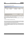
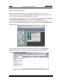
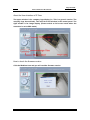
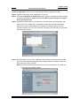
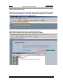
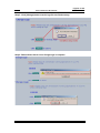
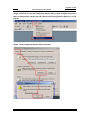
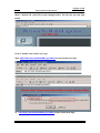
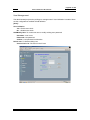
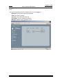
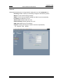
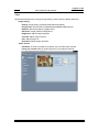
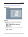
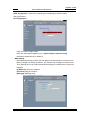
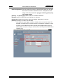
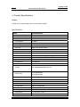
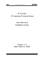
Page 1 of 29
Device manual of IP Cameras
IP-1614GII
IP Cameras Products Series
User Manual &
Installation Guide
Version: 1.0
Date: March 2, 2006
!
!
Page 2 of 29
Device manual of IP Cameras
Table of Contents
TABLE OF CONTENTS..........................................................................................................................2
WHAT IS IP CAMERAS? .......................................................................................................................3
PRODUCT FEATURES............................................................................................................................3
2. PHYSICAL CONNECTIONS..............................................................................................................4
3. INSTALLATION..................................................................................................................................4
CONNECT IP CAM TO NETWORK .........................................................................................................6
CONNECT POWER SUPPLY ...................................................................................................................6
HOW TO RESET ....................................................................................................................................6
START YOUR FIRST TIME NETWORK MONITORING .............................................................................7
HOW TO VISIT THE BUILT-IN WEB ........................................................................................................8
ABOUT THE USER INTERFACE OF IP CAM ..........................................................................................9
HOW TO CHECK THE FIRMWARE VERSION ..........................................................................................9
HOW TO CHANGE THE CONFIGURATIONS..........................................................................................10
HOW TO CHANGE USER LOGO ..........................................................................................................12
HOW TO DISABLE AND ENABLE USER LOGO ......................................................................................15
USER MANAGEMENT .........................................................................................................................16
LOG ....................................................................................................................................................17
NETWORK ..........................................................................................................................................18
VIDEO .................................................................................................................................................19
EVENT ................................................................................................................................................20
4. PRODUCT SPECIFICATIONS .........................................................................................................23
MODELS .............................................................................................................................................23
SPECIFICATIONS: ...............................................................................................................................23
5. APPENDIX ........................................................................................................................................25
DICTATION .........................................................................................................................................25
USE CGI COMMAND TO SETUP GPIO AND EVENTS .........................................................................27
How to configure GPIO Process? ...............................................................................................27
How to Configure Event Process ................................................................................................27
SCENARIO: USE DI TO TRIGGER EVENT AND SEND IMAGES THROUGH MAIL AND FTP..................28
Turn FTP Service on the server ..................................................................................................28
Enable DI status to “ON” ............................................................................................................28
Turn On FTP and Email..............................................................................................................29
Setup Event status ........................................................................................................................29
Check DI type status ....................................................................................................................29
Check Event Status ......................................................................................................................29
Click on DI and you can check your mail box and FTP services .............................................29
Page 3 of 29
Device manual of IP Cameras
1. Product Overview
What is IP Cameras?
IP Cameras is designed for intranet & internet use. Users can view image or change
configurations via built-in web server. The two-layer user-validation prevents any
illegal user to monitor or change configuration once user validation is enabled
Product Features
IP Cameras
CPU: 32 Bits RISC Processor. 16Mb Flash, 64Mb SDRAM
Linux OS
TCP/IP network remote Video transmission system
High performance JPEG/MJPEG compression
Built-in Web sever
Built-in DHCP Client
Built-in Motion Detection
Frame Rate Control
Administrator / User level password protection
Snapshots
On-line firmware upgrade
Frame Rate: NTSC: 30 frame/sec
Page 4 of 29
Device manual of IP Cameras
2. Physical Connections
W/100cm cable
DC 12V
INPUT
Side Panel Connections
Front Panel Connections
IP-R1614GII
3. Installation
Connect Power Supply DC 12V
Ensure your power adapter specification
matchs your power system (ex 110V or 220V)
Connect the adapter to the outlet.
Prepare a PC to link your network with Ethernet
Connect power jack
W/100cm cable
Once the power status is OK.the
LED in red located at the rear panel
of IP cam should light-up.
Ethernet
Page 5 of 29
Device manual of IP Cameras
Network connectivity check
Please check your network connectivity before you start install the product.
Confirm the link status of your LAN is OK. You may try use the following way to
check the network.
Assuming you are under Microsoft Windows 2000 desktop, Click on Start button,
Programs, Accessories, Command PromptΔThen there will be a blank window
appear to wait command input. Please key in the following command to test the
network status.
C:\>ping 192.168.1.1 [Enter]
*Note: the target IP address given above may be correct in common scenarios, if
your network is not configured by IP segment 192.168.1.x, please change the IP
Address to a valid address in your local network. Any difficulties please contact
your network administrator for assistance.
If your network status is OK, the result of above command should like following
Pinging 192.168.1.1 with 32 bytes of data:
Reply from 192.168.1.1 bytes=32 time=10ms TTL=64
…
If you have confirmed your network connectivity is OK, Please proceed to next part
of installation guide, otherwise, contact your network administrator to recover the
problem.
Page 6 of 29
Device manual of IP Cameras
Connect IP cam to network
W/100cm cable
Once the power status is OK.the
LED in red located at the rear panel
of IP cam should light-up.
Connect IP cam to your hub/switch by using a normal RJ45 cable, plug the RJ45
cable into the Ethernet connector locate at the rear panel of the IP cam, another
side connect to your hub/switch.
Connect Power Supply
Connect Power Supply DC 12V
Ensure your power adapter specification
matchs your power system (ex 110V or 220V)
Connect the adapter to the outlet.
Connect power jack
W/100cm cable
Connect the IP cam and power source with the adapter provided, plug the power
adapter into the DC 12V Connector. Once the power status is OK, the LED in red
located at the rear panel of IP cam should light-up.
How to reset
Load IP Cam Default Settings
DC 12V
INPUT
Ethernet
Page 7 of 29
Device manual of IP Cameras
Start your first time network monitoring
Run the “IPLocator” utility, the newly connected IP cam will be listed in the
application window. Please remember its’ IP address.
Open an Internet Explorer Window input the following address into the address
textbox:
http://[IP cam IP Address provided by IPLocator]
After you press on the enter key, the main working interface and video picked by
the camera should appear after a short period. The installation steps are completed.
You may now start your first network monitoring experience.
Note: when you first time enter the working interface, the browser may ask whether
to install a COMWebSurv component, which is used to communicate with our IP
cam product, PLEASE CHOOSE YES to install, otherwise the monitoring function
may not work.
Page 8 of 29
Device manual of IP Cameras
How to visit the built-in web
Launch your Internet Explorer (I.E. 6.0 or above) first, then type the IP cam’s url. (i.e.
http://192.168.1.100). The user validation is disabled as default, no login is necessary. The
user is same as the system administrator(Default : root/pass).
For the first time user visits the IP Cam, the ActiveX(ATLWebSurvCOM) will be downloaded to
the [Downloaded Program File]. Be sure to click the button [Yes] as below.
Notes: Call your system administrator if you have not enough privilege to download the
ActiveX. (i.e. Users should be the administrator to download the ActiveX for Windows 2000/XP
operation system)
You can find the ActiveX ATLWebSurvCOM will be downloaded to the [Downloaded
Program File] folder. The above dialog will pop automatically once new ActiveX is
available(i.e. after firmware upgrade)
Page 9 of 29
Device manual of IP Cameras
About the User Interface of IP Cam
The upper window is for company logo display (i.e. This is a generic version. The
company logo leaves blank). The left side of the window is the control panel. The
right window is for image display. (Please switch to full screen mode when the
resolution is set to VGA mode)
How to check the firmware version
Click the WebCam icon and you will read the firmware version
Page 10 of 29
Device manual of IP Cameras
How to change the configurations
The system administrator: root is the one who has the privilege to change system
configuration if user validation is enabled. The following window will appear when
you click [Options] icon in the control panel (left side of the window). The follow is
the description & field definition.
[System]:
Server Info: Server Model and Firmware Version
Device Name: the name of hardware device.
Video Mode: Video Mode (NTSC or PAL)
Time Zone: Time Zone Setting
Display Option
Show Camera Name: Show Camera Name on Display
Show Date Time: Show Date Time on display
Traffic Control: Bandwidth Setting
Others
Load default configuration: Load the factory default.
Reboot: Reboot the hardware remotely.
Firmware Upgrade : Upload & upgrade the IP cam firmware.
Page 11 of 29
Device manual of IP Cameras
[Firmware Upgrade]: Please follow the standard procedure to upgrade firmware.
Step 0: Stop all unnecessary running application in your PC.
Step 1: Uncheck the [Browse..] and [Upload] motion images in the Motion Detection Setting
and reboot the hardware. Note: You have to make all event setting to be disable,
before you do this step.
Step 2: Upload the firmware: Be sure to upload the correct firmware. Wrong firmware may
cause your IP cam malfunction. It’s possible to take a few minutes to upload the
firmware into memory depending on the network environment. Since too many
unknown situation may occur in the Internet, we strongly recommend you to upgrade
firmware in the Intranet.
Step 3: Write firmware to your IP cam. It will take a few minutes to write firmware into flash.
The IP cam will reboot automatically when writing firmware is complete. Please DO
NOT reboot the device manually.
Note: Any interrupt during writing will cause the IP cam malfunction. The UPS may
prevent the power failure problem.
Page 12 of 29
Device manual of IP Cameras
How to change User Logo
We allow you to use your own logo from version v3.0. User logo will not be erased
when you upgrade firmware in the future. The detailed procedures are as follows:
Step1: Type http://Video ServerIP/LogoUpload.htm
Step 2: Browser the logo file to use and upload to upload it.
Note: The file format must be gif and the max size is 30 K bytes.
Page 13 of 29
Device manual of IP Cameras
Step 3: Click [Change] button to write logo file into flash memory.
Step 4: Reboot Video Server once ChangeLogo is complete.
Page 14 of 29
Device manual of IP Cameras
Step 5: You have to clear the [Temporary Internet files] to take changes effect since
there is always some catch in the I.E. Please click [Tools] [Internet Options..] on the
top bar.
Step 6: Clear [Temporary Internet files] as follows.
Page 15 of 29
Device manual of IP Cameras
Step 7: Refresh I.E. (Click F5) to take changes effect. You will see you new logo
below.
How to disable and enable user logo
Type: http://Video ServerIP/SetOEM.cgi?LOGO=0 to turn off the user logo
or
http://Video ServerIP/SetOEM.cgi?LOGO=1 to turn on the user logo
Page 16 of 29
Device manual of IP Cameras
User Management
The administrator(root) has the privilege to manage users if User Validation is enabled. Here
are the configurations available & field definition.
[User]:
User validation
Yes : Enable user check
No : Disable user check
Add/Modify User: To create new user or modify existing user password
Username : user name
Password: user password
Confirm : user password confirmation
Delete user: To delete existing user
Current User List: The users in the IP cam
Page 17 of 29
Device manual of IP Cameras
Log
The system log will be listed in the window when you click [Log] icon.
Operation: The operation which user operates
Value: The value to change
Client IP: The IP address of client PC
Client MAC: The mac address of client PC
Datetime: date-time which operation occurs
Page 18 of 29
Device manual of IP Cameras
Network
Allows administrator(root) to change network setting when you click [Network] icon.
IP Setting: Please consult you networking manager for the following values
Manual: To set network setting manually.
DHCP: To let IP cam get network setting from DHCP server automatically.
IP Address: IP address of IP cam
Subnet mask: Subnet mask of IP cam
Default Gateway: Default gateway of IP cam
DNS 1/2/3: DNS Server IP if necessary
Http Port: Change the http port of built-in web server (default 80).
(i.e. range 80, 1025 ~ 65535)
Page 19 of 29
Device manual of IP Cameras
Video
Allows administrator(root) to change Image Setting, Traffic Control or Motion Detection.
Image Setting
Quality: Image Quality (Low/Normal/Good/Fine/Excellent)
Images Size: 160x120/176x144/320x240/352x288/640x480/704x576
Rotation: Nomal/180 degree (Upside down)
Advanced: Image preference adjustment
Brightness: Adjust image brightness
Contrast: Adjust image contrast
Hue: Adjust image hue
Saturation: Adjust image saturation
Traffic Control
Unlimited: To send out image at full speed. (up to 30 frames per second)
Frame per second: Delay to send image every x second(mini-second)
Page 20 of 29
Device manual of IP Cameras
Event
This Option contains three major functions: Server Configuration, GPIO
Configuration and Event Configuration
Server Configuration: User can setup Ftp and Mail services that provides the
actions in Event setting.
See figure below:
Allows administrator(root) to configure the mail & ftp setting once motion detected
Mail Setting: if check on Mail motion images, Device will send motion images
Mail Server: Name or IP of Mail server
Username: User name
Password: User password (Password will be validated if checked)
Mail From: Mail sender
Mail To: Mail receiver
Mail Subject: Mail subject
FTP Setting: if check on Mail motion images, Web DVR will upload motion images
FTP Server: FTP Server
Username: User name
Password: User password
Upload Path: Images upload path
Page 21 of 29
Device manual of IP Cameras
GPIO Configuration : Allow user to define types of digital input and their status.
See Figure below:
DO Configuration:
Index: the Index of digital output
DO Type: define type of digital input to : [Normal Open] or [Normal Close]
DO Status: Disable the DO or Enable it.
MSG Setting:
Alert Message function provides user the ability to send message to a remote server.
Device manager can assign ip address , port number and message for remote server.
Thus, Remote server can collect related alert messages via network when events are
triggered.
[IP Adderss]: Server’s IP adderss.
[Port Num]: Http port Number.
[Message]: Message string.
Page 22 of 29
Device manual of IP Cameras
Event Configuration: User can select Event Index to locate Event (range from 0-2) and
also decide to enable or disable this event. Three parts of event
setting will be discussed below: [Trigger condition], [Delay time],
and [Trigger Action]
[Source]: The [Input Type] contains DI0, DI1 and Motion Detection
[Eanble]: Select to Enable the Input Type that you selected.
[Delay time]: Duration that ignores same event trigger. Range from (1-30) sec
[Action]: Including FTP, MAIL, DO and MSG.
After System accepts trigger condition, related actions can be launched. FTP
and MAIL will send image to remote area, thus; [Camera] is necessary for user
to specify. DO is related to its index to specify which digital output (Only 0 is
enable). MSG can send a string to remote server via TCP protocol which will be
released soon.
Page 23 of 29
Device manual of IP Cameras
4. Product Specifications
Models
IP-R1614II: IP Cameras with serial communication support
Specifications:
Items
Specifications
Model
IP-R1614GII
Power
Supply
DC 12V , 350mA(MAX)
Consumption
~3 Watts
Networking
Connectivity
10/100 Ethernet
Protocols
SMTP, FTP, DHCP, HTTP
Internet
Built-In HTTP Web Server, DHCP Client
Event Controls
Trigger By
Alarm Notifications
Sensor
Motion Detect
FTP/Mail motion image, Message
1/4" CCD Image Sensor
Images
Compression
JPEG/MJPEG
Bandwidth Control
Frame Rate Controls
NTSC:640x480/320x240/160x120
Format
Frame Rate
Quality
Image adjustments
PAL: 640x480/352x288/176x144
25 fps @ 320x240
20 fps @ 352x288
5 Level Image Quality
Brightness / Saturation / Contrast / Hue
Security Controls
Access Control
Administrator / User Level Password Protection
Configuration
Http Port configurable
Log
Historical Access Log Management
Operating Environment
Temperature
Humidity
5oC~50oC(45oF~125oF)
20% ~ 80%
Page 24 of 29
Device manual of IP Cameras
LED Indications
Power, Network
Dimension
60mm(W) x 31mm(H) x 84mm(L)
Remote Viewing
Windows 98/2000/XP IE5.X or above
Lens
Built-In Lens
3.7mm/F2.0
Cable
100 flexible cable between the mini lens and the IP CAM
Page 25 of 29
Device manual of IP Cameras
5. Appendix
Dictation
TCP/IP:
Transport Control Protocol/Internet Protocol, the protocol used to transmit data between
hosts in Internet, which provides data verification and error protection
Web:
World Wide Web service is used on Internet widely, It’s provides interactive rich content
by using a web browser
Firmware:
A program built in hardware, which is used to control the hardware, provides software
level functions
MJPEG:
Motion JPEG compression algorithm, use to compress digital video
MPEG:
International standard video compression algorithm
DHCP:
Dynamic host configuration protocol, used on IP network perform IP address, gateway,
DNS server assignment, etc for client computers
DNS:
Domain Name Server/Service is used to translate domain name in to IP address
LAN:
Local area network
WAN:
Wide area network, normally Internet
FTP:
File transportation protocol, used to transmit files between server and client
POP:
Post office Protocol provides Email storage and receive service
Page 26 of 29
Device manual of IP Cameras
SMTP:
Simple mail transportation protocol, provides Email delivery and relay service
Hub:
Physical layer network inter-link device, which simply connect ports together and
broadcasting the data packet to all the port.
Switch:
Data link layer network inter-link device, which provides end-to-end data packet
forwarding,
Router:
Network layer device, which connect networks and provides the function named “Routing”
to find the best way to transport data from source to destination
CGI:
Common gateway interface, a kind of program, running on a web server to provides
dynamic data process function and interacts with users’ action
ActiveX:
Concept and standard gave by Microsoft, which separates program into functioning
pieces named ActiveX Control. These control can be embed into users’ program to give
their specific function.
Page 27 of 29
Device manual of IP Cameras
Use CGI command to setup GPIO and Events
How to configure GPIO Process?
How to setup DI type in the device
http://ServerIP/SetDIType.cgi? Channel=<1>& Enable=<FALSE | TRUE>&
Type=<"NC"|"NO">
Example: Set channel 1 (Input channel) into 'NC' type
http://192.168.2.1/SetDIType.cgi? Channel=1&Type=NC&Enable=TRUE
How to get DI type in the device
http://ServerIP/GetDIType.cgi
How to get DI status into the device
http://ServerIP/GpioInput.cgi?
Example: Get channel status from channel 0 to channel 1
http://192.168.2.1/GpioInput.cgi?
How to set Do status into the device
http://ServerIP/GpioOutput.cgi? Value=ON|OF
Value - 0: LOW
1: HIGH
Example: Set channel 1 (output channel) into LOW
http://192.168.2.1/GpioOutput.cgi? Value=ON|OFF
How to Configure Event Process
How to setup event status?
http://ServerIP/SetEvent.cgi?Reset=<FALSE|TRUE>&Index=<Value>&Input_
Page 28 of 29
Device manual of IP Cameras
Type=<0|1>&Enable_Flag=<FALSE|TRUE>&Action_FTP=<ON|OFF>&Action
_MAIL=<ON|OFF>&Action_DO=<ON|OFF>&Action_MSG=<ON|OFF>&Actio
n_PRESET=<ON|OFF>
Index=0~2
event index from 0 to 2
Input_Type: 0 = Digital Input, 1 = Motion detection
Enable_Flag:FALSE|TRUE, TRUE=ENABLE, FALSE=DISABLE
Action_FTP=<ON|OFF>
Action_MAIL=<ON|OFF>
Action_DO=<ON|OFF>
Action_MSG=<ON|OFF>
Action_PRESET=<ON|OFF>
Input_index=<Value>
Output_index=<Value>
Reset=<FALSE|TRUE>
clean all the event
Example : Setup an Event=> DI trigger "DO" and "MAIL" in first event(that means index =
0)
http://192.168.2.1/SetEvent.cgi?Index=0&Input_Type=0&Enable_Flag=TRUE&Action_F
TP=ON&Action_DO=ON
How to get event status?
http://ServerIP/GetEvent.cgi?Index=<0~2>
Index=0~2
Example: Get Event index =1
http:\\192.168.2.1\GetEvent.cgi?Index=1
Scenario: Use DI to trigger event and send images through Mail and FTP
This scenario can help you to simulate use our digital input to send Mail
or FTP into remote side.
Turn FTP Service on the server
Enable DI status to “ON”
Exp: http://ServerIP/SetDIType.cgi? Channel=1&Type=NC
Page 29 of 29
Device manual of IP Cameras
Turn On FTP and Email
Setup Event status
http://192.168.2.1/SetEvent.cgi?
Index=0&Input_Type=0&Enable_Flag=TRUE&Action_FTP=ON&Action_MAIL=ON
Check DI type status
http://ServerIP/GetDIType.cgi
Diboofm!>!2!
Fobcmf!>!2!
Uzqf!>!OP!
Check Event Status
http://192.168.2.38/GetEvent.cgi
Index =0, Input_Type=DI, Enable_Flag=1, Action_Type= FTP MAIL
Click on DI and you can check your mail box and FTP services