1
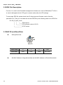
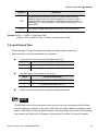
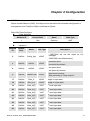
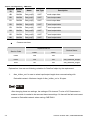
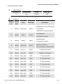
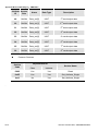
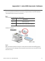
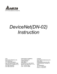
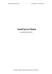
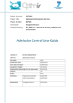
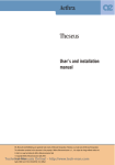
DeviceNet (CME-DN01)
User Manual
DeviceNet is a trademark of the Open DeviceNet Vendor Association, Inc.
The information supplied by this document is subject to change without notice. No
responsibility or liability for the correctness of the information supplied within this
document is assumed.
Table of Contents
Chapter 1 Preface ........................................................................................1-1
1.1 Receiving and Inspection....................................................................1-1
1.2 Using this Manual ...............................................................................1-1
1.3 Features..............................................................................................1-2
Chapter 2 Overview .....................................................................................2-1
2.1 Outline ................................................................................................2-1
2.2 Description..........................................................................................2-1
2.3 Network Example................................................................................2-2
2.4 The Distance of Trunk Line.................................................................2-2
2.5 The Length of Drop Cable...................................................................2-2
2.6 Installation...........................................................................................2-3
Chapter 3 Quick Start ..................................................................................3-1
3.1 Setting Steps for Installation ...............................................................3-1
3.2 EDS File Description...........................................................................3-2
3.3 MAC ID and Baud Rate ......................................................................3-2
3.4 Input/Output Data ...............................................................................3-3
Chapter 4 Configuration..............................................................................4-1
Chapter 5 Troubleshooting .........................................................................5-1
5.1 Network LED.......................................................................................5-1
5.2 Module LED ........................................................................................5-2
5.3 SP LED ...............................................................................................5-2
Appendix A Installation Information ......................................................... A-1
A.1 Dimension ..........................................................................................A-1
A.2 Ambient Conditions ............................................................................A-1
A.3 Product Certifications .........................................................................A-2
Appendix B DeviceNet Object ................................................................... B-1
Appendix C Auto EDS Generator Software.............................................. C-1
Chapter 1 Preface
1.1 Receiving and Inspection
All Delta CME-DN01 have gone through rigorous quality control tests at factory prior to ship.
After receiving CME-DN01, please check that the package includes:
1pcs CME-DN01,
1pcs communication cable (RJ-45, 8 pins),
1 instruction sheet.
1.2 Using this Manual
Chapter 2 describes the use CME-DN01 in field.
Chapter 3 briefly describes setting for installation.
Chapter 4 describes configure the CME-DN01 based upon your requirements.
Chapter 5 describes correct actions by LED.
Appendix A provides the information that you may need to install the CME-DN01.
Appendix B defines the DeviceNet object classes, class services and attributes.
Appendix C describes how to use the “AutoEDS software” to generate EDS file by the
connected drive.
Firmware version for each series should conform with the following table:
Delta AC Drive
Firmware Version
VFD-E
Version 2.02 and above
Revision October 2007, 2006PDD23000003
1-1
Chapter 1 Preface| CME-DN01
1.3 Features
The communications adapter device acts as a gateway from DeviceNet network to
MODBUS network.
Install on the AC drives directly.
Defined as a DeviceNet Communications Device Profile 12 (0xC).
There are 8 I/O addresses used to control the length by setting. The I/O mapping
address can be set by the DeviceNet manage software system, such as RSNetWorx®
from Rockwell. By this way, user can monitor the VFD series by the ladder diagram,
such as RSLogix 500® from Rockwell, and send commands to VFD series.
No external power needed. Power is supplied via RS-485 that is connected to VFD
series. Eight pins RJ-45 cable, which is packed together with CME-DN01, is used to
connect RS-485 of VFD series to RS-485 of CME-DN01 for power. CME-DN01 starts
operation once the connection finished.
DeviceNet Group2 slave functionality includes:
Explicit connection
Polled connection
Object Model
1-2
Revision October 2007, 2006PDD23000003
Chapter 2 Overview
2.1 Outline
MAC address Date Rate
125K
1: Reserved
2: EV
3: GND
4: SG5: SG+
6: Reserved
7: Reserved
8: Reserved
250K
500K
NET MOD SP
AD D1 ADD2 BAUD
CME-DN01
V+
CAN-H
Empty
CAN-L
pin
V-
2.2 Description
Bi colors LEDs
(LED Network, LED Module
and LED SP)
MAC address
Data rate
provide users to analyze DeviceNet network and get the
status of the AC motor drive to solve the problem from the
Chapter 5 Troubleshooting.
used to set the physical address in the DeviceNet network.
used to set the baud rate on the DeviceNet network.
used to connect to the AC motor drive via RJ-45. SG+ and
RS-485 serial port
SG- are for the signal. Besides, the power of CME-DN01 is
provided from the AC motor drive (15V) via this port.
5-pin phoenix connector is used to connect CME-DN01 to
DeviceNet connection
Revision October 2007, 2006PDD23000003
DeviceNet network.
5-pin phoenix connector:
1. Red: V+, power supply.
2. White: CAN_H, signal high.
3. Bare: SHIELD, shield.
4. Blue: CAN_L, signal low.
5. Black: V-, common.
2-1
Chapter 2 Overview| CME-DN01
2.3 Network Example
Power
Supply
trunk line
TR
TR
TR: terminating resistor
: device node
2.4 The Distance of Trunk Line
The distance between any two points must not exceed the maximum cable distance allowed for
the data. Refer to following table for details.
Data rate
Maximum
distance
(flat cable)
Maximum
distance
(thick cable)
Maximum
distance
(mid cable)
Maximum
distance
(thin cable)
125k bit/s
420m (1378 ft)
500m (1640 ft)
300m (984 ft)
100m (328 ft)
250k bit/s
200m (656 ft)
250m (820 ft)
250m (820 ft)
100m (328 ft)
500k bit/s
75m (246 ft)
100m (328 ft)
100m (328 ft)
100m (328 ft)
NOTE: Please refer to the "Appendix B -- DeviceNet Cable Profiles" in the DeviceNet
Specifications for the wiring cable to ensure the max. distance.
2.5 The Length of Drop Cable
A drop line connects a node on the DeviceNet cable system to the DeviceNet trunk. Refer to
following table for details.
2-2
Data Rates
125 Kbps
250 Kbps
500 Kbps
Maximum Drop Length
6 m (20 ft)
6 m (20 ft)
6 m (20 ft)
Cumulative Drop Budget
156 m (512 ft)
78 m (256 ft)
39 m (128 ft)
Revision October 2007, 2006PDD23000003
Chapter 2 Overview| CME-DN01
NOTE: Please refer to the "Appendix B -- DeviceNet Cable Profiles" in the DeviceNet
Specifications for the wiring cable to ensure the max. distance.
2.6 Installation
STEP 1
STEP 2
STEP 3
STEP 4
Revision October 2007, 2006PDD23000003
2-3
Chapter 2 Overview| CME-DN01
This page intentionally left blank
2-4
Revision October 2007, 2006PDD23000003
Chapter 3 Quick Start
3.1 Setting Steps for Installation
Step 1. Setting communication format of the AC drives to 19200 RTU 8, N, 2.
Step 2. Setting frequency source of the AC drives to operate from RS-485.
Step 3. Setting operation source of the AC drives to operate from communication interface.
Note: Refer to the following table for setting step 1, step 2 and step 3.
VFD-E
Description
P02-00=3
Master frequency determined by RS-485
P02-01=3
Operating instructions determined by the RS-485
communication
P09-01=2
19200 bits/second
P09-04=3
Modbus RTU mode, 8 bits, no parity and 2 stop bits
Step 4. Using RJ11 (6 pins) to connect RS-485 of the CME-DN01 and the AC drive.
Step 5. Adding the EDS files (generated from the auto EDS generator software, can be
downloaded from Delta website http://www.delta.com.tw/industrialautomation/) into DeviceNet
management software.
Step 6. Using the operation method of DeviceNet management software for CME-DN01
connection.
Note: Please make sure that VFD-E has set as above table. Or CME-DN01 cannot work
correctly. SP LED should be Green after finishing Step 4 and indicates the CME-DN01 is
communicating with the AC motor drive. If the SP LED is not ON, please refer to chapter 4
Troubleshooting to solve the problem.
Revision October 2007, 2006PDD23000003
3-1
Chapter 3 Quick Start| CME-DN01
3.2 EDS File Description
Function: it is used in the DeviceNet management software tool, such as RSNetWorx® of RA. It
is used to distinguish which VFD type it connects and modify the VFD settings.
To use proper EDS file, please check the AC drives type and firmware version from the
parameter first. Then you can select the correct EDS file by the following name rule of EDS file.
Ex: DN_E_2p03_0.eds
|
|
|
|________VFD software version (V2.03)
|____EDS version
|___________VFD-E series
3.3 MAC ID and Baud Rate
Setting Baud rate
0
BAUD
Switch value
0
1
2
Other
Baud Rate
125K
250K
500K
Not Used
Set MAC Address: Using decimal data set the MAC address on DeviceNet network.
3-2
Revision October 2007, 2006PDD23000003
Chapter 3 Quick Start| CME-DN01
Address
Description
0-63
All addresses should be set within this range. Before setting
address, please make sure that the address you want to use is
available (NOT used by others). The address cannot be used
repeatedly. Or it cannot connect to the network and the NET LED
will be RED.
64-99
This range is illegal addresses and the NET LED will be RED.
Example: ADD1: 3, ADD2: 6, Data Rate: 500k.
Then the value of MAC ID is 36, not 0x36; the Baud rate is 500K.
3.4 Input/Output Data
Default settings of I/O poll message are 4 bytes input and 4 bytes output data.
The information in the following tables is an example:
Input data from AC drivers to DeviceNet (read only)
Word
Function Description
0
Status of AC Driver (2101H)
1
Frequency Command (2102H)
Output data from DeviceNet to AC drivers
Word
Function Description
0
Operate Command (2000H)
1
Frequency command (2001H)
Refer to each AC drive user manual for setting above table.
NOTE
If CME-DN01 has not been set before using, you can use it by connecting with DeviceNet
network without any settings. In this case, CME-DN01 provides a default I/O setting as table
above. CME-DN01 will use this default setting to exchange data with network in I/O message
when power up. Please refer to Chapter 4 Configuration if a desire I/O setting is needed.
Revision October 2007, 2006PDD23000003
3-3
Chapter 3 Quick Start| CME-DN01
This page intentionally left blank
3-4
Revision October 2007, 2006PDD23000003
Chapter 4 Configuration
CME-DN01 also provides other functions for user to set by requirement. CME-DN01 supports an
Object named DataConf (0x95), this object can be accessed via DeviceNet configuration or
management tools. DataConf Object is defined as follows:
Class 0x95 Data Configure
Class Attributes
Attribute ID
Access Rule
Name
Data Type
1
Get
Revision
UINT
Instance 1
Attribute
ID
Access
Rule
Name
Data Type
Description
2
Get/Set
Config_flag
USINT
0: CME-DN01 will use this object for I/O
message
1: CME-DN01 use default setting.
3
Get/Set
NetCtrl
USINT
4
Get/Set
NetRef
USINT
5
Get/Set
LossDNTreat
USINT
0: controlled local.
1: controlled by network.
0: set speed local,
1: set speed by network.
0: Ignore and continue
1: Stop according to “Stop method”.
17
Get/Set
Dlen_in
USINT
Length of input data
18
Get/Set
Dlen_out
USINT
Length of output data
19
Get/Set
Data_in[0]
UINT
1st word input data
20
Get/Set
Data_in[1]
UINT
2nd word input data
21
Get/Set
Data_In[2]
UINT
3rd word input data
22
Get/Set
Data_in[3]
UINT
4th word input data
23
Get/Set
Data_in[4]
UINT
5th word input data
24
Get/Set
Data_in[5]
UINT
6th word input data
25
Get/Set
Data_in[6]
UINT
7th word input data
26
Get/Set
Data_in[7]
UINT
8th word input data
Revision October 2007, 2006PDD23000003
4-1
Chapter 4 Configuration| CME-DN01
Attribute
ID
Access
Rule
Name
Data Type
Description
st
49
Get/Set
Data_out[0]
UINT
1 word output data
50
Get/Set
Data_out[1]
UINT
2nd word output data
51
Get/Set
Data_out[2]
UINT
3rd word output data
52
Get/Set
Data_out[3]
UINT
4th word output data
53
Get/Set
Data_out[4]
UINT
5th word output data
54
Get/Set
Data_out[5]
UINT
6th word output data
55
Get/Set
Data_out[6]
UINT
7th word output data
56
Get/Set
Data_out[7]
UINT
8th word output data
Common services
Implemented for
Service Name
Service Code
Class
Class
0X05
Yes
Yes
Reset
0x0E
Yes
Yes
Get_Attribute_Single
0x10
No
Yes
Set_Attribute_Single
Explanation: User can set following variables for DataConf object by the requirement.
1.
dlen_in/dlen_out: for user to select input/output length when communicating with
DeviceNet network. Maximum length of dlen_in/dlen_out is 16 bytes.
NOTE
After changing these two settings, the settings of Rx size and Tx size of I/O Parameters in
scanner module is needed to be same as these two settings. Or there will be fault and cannot
connect to DeviceNet network when running CME-DN01.
4-2
Revision October 2007, 2006PDD23000003
Chapter 4 Configuration| CME-DN01
2.
data_in1~data_in8: used to save 16 bytes data of each Modbus address of AC drive. For
example, if address data in data_in1 is 0x2000, it will send the first word of data to AC
drive address 0x2000. Similarly, if address data in data_out1 is 0x2101, CME-DN01 will
send the first word of data in AC drive address 0x2101 to DeviceNet network. The length
of data_in/data_out is determined by dlen_in/dlen_out. After finishing setting, the
command from CME-DN01 to the AC motor drive won’t be valid immediately.
Re-power on
The modified setting will be valid via service “RESET “.
NOTE
the column length is UINT, i.e. word (2 bytes). An error will occur when inputting byte for data
size.
3.
NetCtrl/NetRef: used to determine if CME-DN01 is controlled via DeviceNet network. If it
is 0, DeviceNet network can’t control CME-DN01 and user can modify control
command/frequency command directly. If it is 1, CME-DN01 is controlled by DeviceNet
network via PLC ladder diagram commands.
4.
LossDNTreat: used to determine to stop the AC motor drive or not when losing
connection with DeviceNet network.
0: AC drive will still in current running status when losing connection with DeviceNet.
1: AC drive will stop running when losing connection with DeviceNet by the AC drive’s
setting.
5.
config_flag: factory setting is 0. It needs to be set to 1 when reset all settings to the
factory settings.
6.
The following table is the factory setting of DataConf Object
Attribute ID
Name
Value(Hex)
1
sfversion
2
config_flag
0000H
3
NetCtrl
0001H
4
NetRef
0001H
5
LossDNTreat
0001H
17
dlen_in
0002H
18
dlen_out
0002H
Revision October 2007, 2006PDD23000003
4-3
Chapter 4 Configuration| CME-DN01
Attribute ID
Name
Value(Hex)
19
data_in[0]
2000H
20
data_in[1]
2001H
21
data_in[2]
2002H
22
data_in[3]
0000H
23
data_in[4]
2000H
24
data_in[5]
2001H
25
data_in[6]
2002H
26
data_in[7]
0000H
49
data_out[0]
2101H
50
data_out[1]
2103H
51
data_out[2]
2104H
52
data_out[3]
010AH
53
data_out[4]
2101H
54
data_out[5]
2103H
55
data_out[6]
2104H
56
data_out[7]
010AH
.
4-4
Revision October 2007, 2006PDD23000003
Chapter 5 Troubleshooting
This chapter provides LEDs information, and corrective actions for solving problem.
MAC address Date Rate
125K
1: Reserved
2: EV
3: GND
4: SG5: SG+
6: Reserved
7: Reserved
8: Reserved
250K
500K
NET MOD SP
ADD1 ADD2 BAUD
CME-DN01
V+
CAN-H
Empty
CAN-L
pin
V-
5.1 Network LED
State
Indication
Corrective Actions
1.
Verify that the power supply of CME-DN01 is
connected and the power is applied to the
CME-DN01.
LED is off
No power or duplicate ID
not completed.
2.
Make sure one or more nodes are
communicating on the network.
3.
Make sure at least one other node on the
network is in operation at the same time and
data rate is the same as the CME-DN01.
Flashing
Green LED
CME-DN01 is connected to
the network but something
wrong with the network
configuration setting.
Green LED
Online and connected.
One or more connections
established
Flashing Red
LED
Online but failed to
establish connection.
Revision October 2007, 2006PDD23000003
5-1
Chapter 5 Troubleshooting| CME-DN01
State
Indication
Corrective Actions
1.
2.
Red LED
Network failure. Failed
duplicate ID or Bus-off.
Ensure that all nodes have unique address.
If all node addresses are unique, check
network for correct media installation.
3.
Ensure that the address is NOT in the illegal
range.
5.2 Module LED
State
Indication
Corrective Actions
LED is off
No power/not online
Ensure that the connected AC drive is powered
and connected to the CME-DN01.
Flashing
Green LED
Waiting for I/O data. No
I/O, or PLC is in program
mode
CME-DN01 has passed all operation tests and
waits to transmit I/O data between the CME-DN01
and the AC drives.
Green LED
Flashing Red
LED
Red LED
I/O is in running mode
Configuration problem. Bad
Reset internal I/O data of the CME-DN01. Please
CRC of CME-DN01
refer to Data Configuration address assignment
parameters or flash
for detail.
program.
Hardware Failure. Failed
internal or external RAM
test.
Return to the factory.
5.3 SP LED
State
Indication
LED is off
No power
Flashing
Green LED
CME-DN01 is reading the
factory settings of the AC
drives. CME-DN01 gets
parameters information of
the AC drives and
initializes some Identity
attributes.
Green LED
CME-DN01 and the AC
drives are communicating.
Flashing Red
LED
5-2
Corrective Actions
No power is applied to the device.
To check if the setting of communication format of
CRC check error/AC drives
the AC drives is correct. Please refer to the
return error information.
installation settings for detail.
Revision October 2007, 2006PDD23000003
Chapter 5 Troubleshooting| CME-DN01
State
Indication
Corrective Actions
1.
Red LED
Connection failure/no
connection
To check if the connection between the AC
drive and RS-485 of CME-DN01 is correct.
2.
Re-wire the AC drive connection and ensure
that the wire specification is correct.
Revision October 2007, 2006PDD23000003
5-3
Chapter 5 Troubleshooting| CME-DN01
This page intentionally left blank
5-4
Revision October 2007, 2006PDD23000003
Appendix A Installation Information
Appendix A provides the information that you may need to install the CME-DN01.
A.1 Dimension
3
4
250K
N ETM OD SP
ADD1 AD D2 BAUD
CME-DN01
2
72.2 [2.84]
57.3 [2.26]
500K
14.3 [0.57]
59.7 [2.35]
125K
5
1
35.8 [1.41]
3.5 [0.14]
UNIT: mm(inch)
A.2 Ambient Conditions
Operation:
Temperature: -10oC to 40 oC (14 oF to 104 oF) without dust cover.
Storage:
Temperature: -20 oC to 60 oC (-4 oF to 140 oF)
Relative Humidity: Less than 90﹪, no condensation allowed.
Transportation:
Temperature: -20 oC to 60 oC (-4 oF to 140 oF)
Relative Humidity: Less than 90﹪, no condensation allowed.
Pollution Degree:
2: good for a factory type environment.
Revision October 2007, 2006PDD23000003
A-1
Appendix A Installation Information| CME-DN01
A.3 Product Certifications
This product meets the following certifications.
Certifications
A-2
Description
UL
UL508C
CE
EN50178 and EN61800-3
Revision October 2007, 2006PDD23000003
Appendix B DeviceNet Object
Appendix B defines the DeviceNet object classes, class services and attributes. The following
information about the DeviceNet objects can be accessed by using Explicit Messages. Refer to
the DeviceNet specification for using Explicit Messages. You can get the following table
information from the CME-DN01 through any DeviceNet management tool.
Ex. How to get the Vendor ID through Explicit Message?
Request data
Value
Description
Service
0x0E
Get Attribute Single
Class
0x01
Identity Object
Instance
0x01
Instance 1
Attribute
0x01
Vendor ID
Response data
Value
Service
0x8E
data
0x031F
Description
Successful
ID = 0x031F(Delta)
Object Classes
CME-DN01 supports following object classes and user can read or write them via the DeviceNet
management tool.
Class
Object
0x01
Identity Object
0x02
Message Router Object
0x03
DeviceNet Object
0x05
Connection Object
0x0F
Parameter Access Object
0x95
DataConf Object
Revision October 2007, 2006PDD23000003
B-1
Appendix B DeviceNet Object| CME-DN01
Class 0x01 Identity Object
This object provides identification and general information about the device.
Class Attributes
Attribute ID
1
2
3
6
7
Access Rule
Get
Get
Get
Get
Get
Name
Revision
MaxInstance
NumberofInstances
MaxIdClass
MaxIdInstance
Data Type
UINT
UINT
UINT
UINT
UINT
Name
VendorId
DeviceType
ProductCode
Revision
MaxRev
MinRev
Status
Sn
ProdName
StrLen
ASCIIStr
Data Type
UINT
UINT
UINT
Instance 1: Drive Instance
Attribute ID
1
2
3
Access Rule
Get
Get
Get
4
Get
5
6
Get
Get
7
Get
USINT
USINT
WORD
UDINT
USINT
STRING
Common Services
Implemented for
Service Code
Instance
No
Yes
0x0E
Yes
Yes
Get_Attribute_Single
0x11
Yes
No
Find_Next_Object_Instance
0x05
B-2
Service Name
Class
Reset
Revision October 2007, 2006PDD23000003
Appendix B DeviceNet Object| CME-DN01
Class 0x02 Message Router
The Message Router Object provides a messaging connection point to serve any object class or
instance in the Client.
Class attributes
Attribute ID
Access Rule
Name
Data Type
1
Get
Revision
UINT
6
Get
MaxIdClass
UINT
7
Get
MaxIdInstance
UINT
Access Rule
Name
Data Type
2
Get
NumAvailable
UINT
3
Get
NumActive
UINT
Instance 1
Attribute ID
Common Services
Service Code
0x0E
Implemented for
Class
Instance
Yes
Yes
Revision October 2007, 2006PDD23000003
Service Name
Get_Attribute_Single
B-3
Appendix B DeviceNet Object| CME-DN01
Class 0x03 DeviceNet Object
The DeviceNet Object provides the configuration and status of a DeviceNet port. Each CME-DN01
supports one DeviceNet object for a physical connection to the DeviceNet communication link.
Class Attributes
Attribute ID
Access Rule
Name
Data Type
1
Get
Revision
UINT
Instance 1: Drive Instance
Attribute ID
Access Rule
Name
Data Type
1
2
Get
MACID
USINT
Get
BaudRate
USINT
3
Get/Set
BusofInterrupt
BOOL
4
Get/Set
BusofCounter
USINT
5
Get
AllocationChioce
AllocationInfo
MasterNodeAddress
BYTE
USINT
6
Get
MACIDSwitchChanged
BOOL
7
Get
BaudRateSwitchChanged
BOOL
8
Get
MACIDSwitchValue
USINT
9
Get
BaudRateSwitchValue
USINT
Common Services
Service
Code
B-4
Implemented for
Service Name
Class
Instance
0x0E
Yes
Yes
Get_Attribute_Single
0x10
No
Yes
Set_Attribute_Single
0x4B
No
Yes
Allocate_Master/Slave_Connection_Set
0x4C
No
Yes
Release_Master/Slave_Connection_Set
Revision October 2007, 2006PDD23000003
Appendix B DeviceNet Object| CME-DN01
Class 0x05 Connection Object
The Connection Class allocates and manages the internal resources associated with both I/O and
Explicit Messaging Connections. The specific instance generated by the Connection Class is called a
Connection Instance or a Connection Object.
Class attributes
Attribute ID
Access Rule
Name
Data Type
1
Get
Revision
UINT
Instance 1: Master/Slave Explicit Message Connection
Attribute
ID
Access
Rule
Name
Data Type
1
Get
State
USINT
2
Get
InstanceType
USINT
3
Get
TransportClassTrigger
USINT
4
Get
ProducedConnectionId
UINT
5
Get
ConsumedConnectionId
UINT
6
Get
InitialCommCharacteristics
BYTE
7
Get
ProducedConnectionSize
UINT
8
Get
ConsumedConnectionSize
UINT
9
Get/Set
ExpectedPackedRate
UINT
12
Get/Set
WatchdogTimeoutAction
USINT
13
Get
Produced Connection Path
Length
USINT
14
Get
Produced Connection Path
EPATH
15
Get
Consumed Connection Path
Length
USINT
16
Get
Consumed Connection Path
EPATH
Revision October 2007, 2006PDD23000003
B-5
Appendix B DeviceNet Object| CME-DN01
Instance 2: Polled I/O Connection
Attribute
ID
Access
Rule
Name
Data
Type
1
Get
State
USINT
2
Get
InstanceType
USINT
3
Get
TransportClassTrigger
USINT
4
Get
ProducedConnectionId
UINT
5
Get
ConsumedConnectionId
UINT
6
Get
InitialCommCharacteristics
BYTE
7
Get
ProducedConnectionSize
UINT
8
Get
ConsumedConnectionSize
UINT
9
Get/Set
ExpectedPackedRate
UINT
12
Get/Set
WatchdogTimeoutAction
USINT
13
Get
Produced Connection Path
Length
USINT
14
Get
Produced Connection Path
EPATH
15
Get
Consumed Connection
Path Length
USINT
16
Get
Consumed Connection
Path
EPATH
Common Services
Service
Code
B-6
Implemented for
Service Name
Class
Instance
0x05
No
Yes
Reset
0x0E
Yes
Yes
Get_Attribute_Single
0x10
No
Yes
Set_Attribute_Single
Revision October 2007, 2006PDD23000003
Appendix B DeviceNet Object| CME-DN01
Class 0x0F Parameter Object
Use of the Parameter Object provides a known, public interface to a device’s configuration data. In
addition, this object also provides all the information necessary to define and describe the device’s
individual configuration parameters.
Class attributes
Attribute ID
Access Rule
Name
Data Type
1
Get
Revision
UINT
2
Get
MaxInstance
UINT
8
Get
ParaClassDescriptor
WORD
9
Get
ConfAssemblyInst
UINT
10
Get
NativeLanguage
USINT
We can get the number of parameters of the drive that connected to the CME-DN01 by Instance 0
and Attribute2.
The number of instances depends on the number of parameters in the drive.
Ex:
Instance
Description
0
Class attributes
1
Drive parameter 1
2
Drive parameter 2
:
:
N
Drive parameter N
Revision October 2007, 2006PDD23000003
B-7
Appendix B DeviceNet Object| CME-DN01
Instance: Parameter Instance
Attribute ID
Access Rule
Name
Data Type
1
Get/Set
Parameter Value
--
2
Get
Link Path Size
USINT
3
Get
Link Path
--
4
Get
Descriptor
WORD
5
Get
Data Type
USINT
6
Get
Data Size
USINT
Common Services
Service Code
B-8
Implemented for
Service Name
Class
Instance
0X05
Yes
No
Reset
0x0E
Yes
Yes
Get_Attribute_Single
0x10
No
Yes
Set_Attribute_Single
Revision October 2007, 2006PDD23000003
Appendix B DeviceNet Object| CME-DN01
Class 0x95 DataConf Object
Class attributes
Attribute ID
Access Rule
Name
Data Type
1
Get
Revision
UINT
Instance 1
Attribute Access
ID
Rule
2
Get/Set
Name
Data Type
Config_flag
USINT
Description
0: CME-DN01 will use this object for
I/O message
1: CME-DN01 use default setting.
0: controlled local.
3
Get/Set
NetCtrl
USINT
1: controlled by network.
0: set speed local,
4
Get/Set
NetRef
USINT
1: set speed by network.
0: Ignore and continue
5
Get/Set LossDNTreat
USINT
1: Stop according to “Stop method”.
17
Get/Set
dlen_in
USINT
Length of input data
18
Get/Set
Dlen_out
USINT
Length of output data
19
Get/Set
Data_in[0]
UINT
1st word input data
20
Get/Set
Data_in[1]
UINT
2nd word input data
21
Get/Set
Data_In[2]
UINT
3rd word input data
22
Get/Set
Data_in[3]
UINT
4th word input data
23
Get/Set
Data_in[4]
UINT
5th word input data
24
Get/Set
Data_in[5]
UINT
6th word input data
25
Get/Set
Data_in[6]
UINT
7th word input data
26
Get/Set
Data_in[7]
UINT
8th word input data
Revision October 2007, 2006PDD23000003
B-9
Appendix B DeviceNet Object| CME-DN01
Attribute Access
Name
Data Type
Description
Get/Set
Data_out[0]
UINT
1st word output data
50
Get/Set
Data_out[1]
UINT
2nd word output data
51
Get/Set
Data_out[2]
UINT
3rd word output data
52
Get/Set
Data_out[3]
UINT
4th word output data
53
Get/Set
Data_out[4]
UINT
5th word output data
54
Get/Set
Data_out[5]
UINT
6th word output data
55
Get/Set
Data_out[6]
UINT
7th word output data
56
Get/Set
Data_out[7]
UINT
8th word output data
ID
Rule
49
Common Services
Service
Code
Implemented for
Service Name
Class
Instance
0X05
Yes
Yes
Reset
0x0E
Yes
Yes
Get_Attribute_Single
0x10
No
Yes
Set_Attribute_Single
.
B-10
Revision October 2007, 2006PDD23000003
Appendix C Auto EDS Generator Software
For correct display the drive that connected to the CME-DN01 in the DeviceNet management
tool, we can generate the EDS file for the drive by using the software “Auto EDS Generator”.
The operation steps are shown in the following.
Step1.
Please set drive’s parameters as following table.
VFD-E
Description
P09.01=2
19200 bits/second
P09.04=3
RTU mode, 8 bits, no parity and 2 stop bits
Hardware Connection
Step2.
Make sure that the hardware connection is correct and then execute the AutoEDS program.
Following screen will be displayed. After successful communication test, the AutoEDS will be
executed correctly.
Revision October 2007, 2006PDD23000003
C-1
Appendix C Auto EDS Generator Software|CME-DN01
Step3.
After pressing the 【Start】button at the upper-left corner, program will start generating the EDS
file as shown in the following.
C-2
Revision October 2007, 2006PDD23000003
Appendix C Auto EDS Generator Software|CME-DN01
Step4.
After generating EDS file, you will get a pop-up window for saving this EDS file.
Revision October 2007, 2006PDD23000003
C-3
Appendix C Auto EDS Generator Software|CME-DN01
This page intentionally left blank.
C-4
Revision October 2007, 2006PDD23000003