1
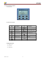
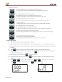
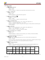
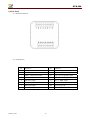
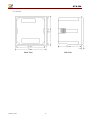
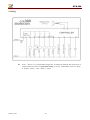
GTR-300
Generator Controller
User Manual
Web Site:http://www.monicon.com.tw
E - m a i l :s a l e s @ m o n i c o n . c o m . t w
File version: V03
-1-
GTR-300
1. Feature
LCD Screen shows:RPM Value、Run Acc Hour Value、Battery Volt value、.
Mode Button includes:Off、Auto、Manual、Clear、Info and Setup
Values displayed on LCD:Over Speed、High Water Temp.、Low Oil Pressure、Over Crank、Low
Battery、Low RPM.
Directly setup from the control panel.
Wide adjustable working Volt from DC 8 V to 36 V.
Use the Terminal with high secure and easy install
Low power consumption in standby mode: 25 mA@12V ; 20 mA@24V
LCD present clear system status with two color back light
2. Introduction
GTR-300, the compact type digital Engine controller, can real-time display the fault
message and the immediate status of Engine. When the system fault of Gen-set occurs, it can
be showed from the indication LCD to inform the maintenance. In setup mode, can adjust the
setup value of parameter to suiting with your Gen-set feature.
3. Specification
DC Work Volt
8~36 V (DC)
Power Consumption
Max. 250mA @ 12 V; 160mA @ 24 V
Measured Frequency
Range of Volt detector :5 ~ 70 Vp-p
Range of Signal input :0~10000 Hz
Range of RPM : 0~9999 Rpm
DC Volt Gauge
Range:10~31 V
Relay Output
5 A / 30V
Work Temperature
-20 ℃~70 ℃
Size
72 mm × 72 mm × 58 mm
Punch Size
68 mm × 68 mm
Weight
175 g (0.38lb)
Version: V03
-2-
GTR-300
4. Control Panel Description
4.1 Panel Outlook
4.2 LCD Icon Descriptions
Icon
AUTO
OFF
MAN.
Description
Icon
Auto Mode
Parameter Store
Off
Parameter Up-load
Manual Mode
Parameter Under -Load
Over Speed
Parameter Number
Low Oil Pressure
LOWBATT Low Battery Volt
High Water Temp.
DC System
Crank Failure
Volt Unit
Hr
Emergency Stop
Run
Run Hour
RPM Value
Low RPM
4.3 Display Information
4.3.1 Battery Volt
4.3.2 Run Hour
4.3.3 RPM Value
Version: V03
Description
-3-
GTR-300
4.4 Button Function
a. In standby mode, push it to shift the mode of Run and Code.
b. In setup mode, push it as the shifting button of information page. (Down)
a. In code mode, push it to enter the code #1
b. In standby mode, push it to automatically start the Gen-set.
c. In setup mode, push it as the shifting button of information page. (UP)
a. In code mode, push it to enter the code #2
b. Push it can shift the relative information of Gen-set. The display order: Battery
Volt Frequency.
c. In setup mode, push it to increase one unit value of current parameter. (Increase)
a. In code mode, push it to enter the code #3
b. In standby mode, push it to manual start Gen-set.
c. In setup mode, push it to decrease one unit value of current parameter. (Decrease)
a. In faulty stop status, push it to clear the fault signal.
b. In setup mode, push this button to exit setup page and cancel current parameter setting.
a. In code mode, this button is Enter button.
b. In run status, it can enable the stop function.
c. In Setup mode, push down this button to save the current setup of user.
5. Panel Operation
5.1. Wire the wiring accurately according Monicon manual.
5.2. Plug on the DC power to battery. Then all the icon of LCD will light up. User can test the function of LCD.
5.3. Once the controller opened, the system mode is under Auto. The Info page will show the battery volt and the
run hours.
5.4. Push
button to shift the system mode. The order is running operation and code setting.
5.5. In【OFF】mode, the controller only accept user push
button to start Gen-set. In this mode, the
crank time function will off.
5.6. After Gen-set run successfully, push
can stop the Gen-set.
5.7. In code mode, key in the code 101 and push
.After those procedures, the code mode shift to setup
mode.
5.8. Push
Push
and
to shift parameter page. Push
to up or down the setting value.
to quit current setup.
will save the setup parameter. Push
Code Mode Display
Version: V03
and
Parameter Setup Display
-4-
GTR-300
6. Parameter Setup
6.1.
Stop Time OFF
Time:5~40 Sec
Default:10 Sec
Parameter explanation:Setup the time of engine shut down and the interval of crank
6.2.
Preheat Time
Time:0~30 Sec
Default:0 Sec
Parameter explanation:Preheat time before engine start
6.3.
Crank Account
Frequency:1~9 Times
Default:3 Times
Parameter explanation:Setup the account of Gen-set crank
6.4.
Shut Down Time
Time:0~1250 Sec (Setting Value 0~250,The base value of Idle time is 5 )
Default:0 (Example:Setting Value 1,1*5 = 5 Sec)
Parameter explanation:Setup the cooling down time of engine. (At faulty situation or manual stop, this
parameter disables.)
6.5.
Idle Time
Time:0~1250 Sec (Setting Value 0~250,The base value of Idle time is 5)
Default:0 (例:Setting Value 1,1*5 = 5 Sec)
Parameter explanation:Setup the Idle speed time of engine
6.6.
Low Battery Volt LOWBATT
Range:9~32 V
Default:11 V
Parameter explanation:Setup the lower limit of battery volt. As battery volt under the standard,
controller occur the alarm of low battery volt.
6.7.
Over Speed
Range:1000~5000 RPM (Setting Value 100~500,The base value of Over Speed is 10)
Default:1980 Rpm
Parameter explanation:Setup the supremum of frequency. If the frequency of Engine surpasses the upper
limit, controller orders the Gen-set to stop and produce the fault of over speed.
6.8.
Function Selection
Range:0~63
Default:15 (Turn off the functions of disconnect starter by oil pressure and low RPM detection)
Parameter explanation:According demand to select the function of system
Disconnect
motor by Emergency Low Oil
Low RPM
Stop
Pressure
oil pressure
build up
Weight
Example
Disconnect motor by
oil pressure build up
Disable
⌦
⌦
Version: V03
32
16
8
4
High Water
Temperature
Over Speed
2
1
Result
15
Note 1:Above list, present【enable】, present【disable】
Note 2:Math method: multiply the corresponding bit of setup value and the weight first, and then
-5-
GTR-300
⌦
6.9.
add all bits totally.
Example:The value for disabling disconnect starter by oil pressure and low RPM protection is:
8 + 4 + 2 + 1 = 15
Circuit Close floor
Frequency:1200~2500 Rpm (Setting Value 120~250,The base value of Circuit Close floor is 10)
Default:1350 Rpm
Parameter explanation:1. This parameter sets the RPM value for closing the load circuit. When the RPM
is higher than this setting, the controller sends signal for closing the load circuit
for one second. (Needs relay to perform this function)
2. When the RPM is under this setting, controller will not trigger the signal for
closing the load circuit and low speed icon is displayed.
Input Switch type setup
Value Range:0~15
Default:5 (setting for emergency stop switch is normally closed)
Parameter explanation:According the demand to select the type of input switch
6.10.
Start by outer switch High Temperature
only
Switch
Emergency Stop
Switch
Low Oil Pressure
Switch
Weight
8
4
2
1
Example
Disable
N/O
N/C
N/O
⌦
⌦
⌦
Result
5
Note 1:If 【Start by outer switch】is enabled, the keypad on the controller will be disabled, only
the outer switch ( Pin 12 on the input ) can control the start and stop of the engine.
Note 2:Math method: multiply the corresponding bit of setup value and the weight first, and then
add all bits totally.
Example:The setting is 4 + 1= 5
6.11.
RPM Multiplier
Value Range:1~200
Default:112
Parameter explanation:Use for setting the ratio.
6.12.
RPM Divisor
Range:1~200
Default:10
Parameter explanation:Use for setting the ratio.
** How to calculate the Multiplier & Divisor?
1. Setting the Multiplier value and Divisor value equal to 1 to get the pulse.
2. Use the counter to detect the engine RPM.
3. [Pulse x Multiplier ÷ Divisor = RPM] →[Multiplier /Divisor = RPM /Pulse]
4. Ex1, pulse is detected from charger
a. Pulse = 321Hz. b. Engine = 1800 RPM. c. 1800/321=5.6. d. You can set the multiplier =56 and divisor
=10.
5. Ex2, pulse is detected from pick up
a. Pulse = 3897Hz. b. Engine = 1500 RPM. c. 1500/3897=0.3849. d. You can set the multiplier =38 and
divisor =100.
Version: V03
-6-
GTR-300
** Deviation can be eliminated by different multiplier and divisor. The ratio can be totally exact
theoretically.
6. Ex3, pulse is detected from pick up, flywheel teeth count is already known, assume
a. Flywheel teeth count is 208
b. 60/208(teeth count)=30/104=15/52
c. Now we can assume multiplier is 15 and divisor is 52, or multiplier is 30 and divisor is 104
6.13.
Time delay of oil pressure switch
Time : 0.4~6 Sec (Setting value 2~30,the base value of delay time is 0.2)
Default:1.2 Sec (Setting value 6, 6*0.2=1.2 Sec)
Parameter explanation:Once setup “disconnect motor by oil pressure set up” as current system set up. If
the start procedure be activated, the delay timer will be trigger. In other word, when oil pressure built up
timer is time out and oil pressure build up successfully, the controller will order starter motor disconnect
with engine. This parameter is unconcerned with the faulty delay time of low oil pressure.
6.14.
RELAY 0 Output function selection
Value Range:0~6
Default:4 (Preheat)
Parameter explanation:User can select the output function of REALY 0
(0:Alarm,1:Trip,2:Stop,3:Circuit Close,4:Preheat,5:Idle,6: Low RPM)
6.15.
RELAY 1 Output function selection
Value Range:0~6
Default:2 (Stop)
Parameter explanation:User can select the output function of REALY 1
(0:Alarm,1:Trip,2:Stop,3:Circuit Close,4:Preheat,5:Idle,6: Low RPM)
6.16. PARA E RELAY 2 Output function selection
Range:0~6
Default:0 (Alarm)
Parameter explanation:User can select the output function of REALY 2
(0:Alarm,1:Trip,2:Stop,3:Circuit Close,4:Preheat,5:Idle,6: Low RPM)
7. System Parameter
7.1. Trigger Delay of Emergency Stop:0.1 Sec/Action:Stop
7.2. Trigger Delay of over speed:2 Sec/Action:Stop
7.3. Trigger Delay of High Temperature:1 Sec/Action:Stop
7.4. Trigger Delay of Low Oil Pressure:1 Sec/Action:Stop
7.5. Trigger Delay of Low Battery Volt:5 Sec/Action:Alarm
7.6. Trigger Delay of Low RPM: 2 Sec/Action : Alarm
7.7. Disconnect starter motor by RPM:480 Rpm
7.8. Crank Time:10 Sec
7.9. Protection Pause function time:10 Sec (During 10 second after the Gen-set start normally, controller pause
the faulty protection function except the emergency stop function and over speed
function.)
Version: V03
-7-
GTR-300
8. Back Panel
8.1. Back Panel Outlook
8.2. Pin Definition
Version: V03
Pin
Definition
Pin
1
Battery B+
9
EMS - Emergency stop, Input
2
Battery B-
10
HWT – High water temp., Input
3
Motor – Output starter relay
11
LOP – Low oil pressure, Input
4
Valve – Output fuel valve relay
12
ATS – Auto start, Input
5
RELAY 2 Output
13
ALT 1 – RPM, Input 1
6
RELAY 1 Output
14
ALT 2 – RPM, Input 2
7
RELAY 0 Output
VR
Speed verify, VR
8
CHGR – Charger fire point
-8-
Definition
GTR-300
8.3. Outlook
Back View
Version: V03
Side View
-9-
GTR-300
9. Wiring
⌦
Version: V03
Note 1:The pin 5~7 is programmable output relay, according user demand. The setting value of
output function just refer to ”6、Parameter Setup” 6.12~6.14 . Default Relay value are:Relay
0:Preheat,Relay 1:Stop,Relay 2:Alarm
-10-