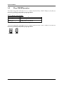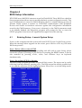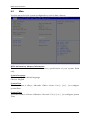
1
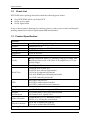
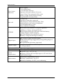
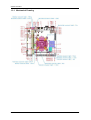
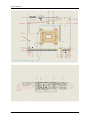
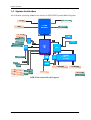
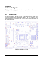
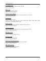
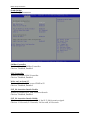
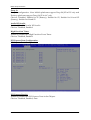
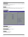
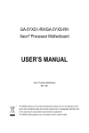
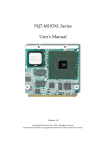
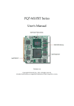
PGB-5120S
Gaming Board
User's Manual
Version 1.1
Copyright © Portwell, Inc., 2014. All rights reserved.
All other brand names are registered trademarks of their respective owners.
Preface
Table of Contents
How to Use This Manual
Chapter 1 System Overview ....................................................................................................... 1-1
1.1 Introduction ....................................................................................................... 1-1
1.2 Check List ........................................................................................................... 1-2
1.3 Product Specification ........................................................................................ 1-2
1.3.1 Mechanical Drawing................................................................................ 1-4
1.4 System Architecture.......................................................................................... 1-6
Chapter 2 Hardware Configuration ........................................................................................... 2-1
2.1 Jumper Setting ................................................................................................... 2-1
2.2 Connector Allocation ........................................................................................ 2-2
Chapter 3 System Installation .................................................................................................... 3-1
3.1 Intel LGA-1155 Processor ................................................................................. 3-1
3.2 Main Memory .................................................................................................... 3-5
3.3 Installing the Single Board Computer............................................................ 3-6
3.3.1 Intel® BD82H61 PCH Chipset ............................................................... 3-6
3.3.2 Intel® Core i processors integrated Graphics Engine ........................ 3-6
3.3.3 Realtek Ethernet Controller .................................................................... 3-6
3.3.4 Audio Controller ...................................................................................... 3-6
3.4 Clear CMOS Operationr................................................................................... 3-7
Chapter 4 BIOS Setup Information ............................................................................................ 4-1
4.1 Entering Setup -- Launch System Setup ........................................................ 4-1
4.2 Main .................................................................................................................... 4-2
4.3 Advanced ........................................................................................................... 4-3
4.4 Chipset .............................................................................................................. 4-26
4.5 Boot ................................................................................................................... 4-32
4.6 Security ............................................................................................................. 4-35
4.7 Save & Exit ....................................................................................................... 4-36
Chapter 5 Troubleshooting ........................................................................................................ 5-1
5.1 Hardware Quick Installation........................................................................... 5-1
5.2 BIOS Setting ....................................................................................................... 5-2
5.3 FAQ ..................................................................................................................... 5-3
Appendix A
Appendix B
Preface
How to Use This Manual
The manual describes how to configure your PGB-5120S system to meet various
operating requirements. It is divided into five chapters, with each chapter addressing
a basic concept and operation of Single Host Board.
Chapter 1 : System Overview. Presents what you have in the box and give you an
overview of the product specifications and basic system architecture for this series
model of single host board.
Chapter 2 : Hardware Configuration. Shows the definitions and locations of Jumpers
and Connectors that you can easily configure your system.
Chapter 3 : System Installation. Describes how to properly mount the CPU, main
memory and Compact Flash to get a safe installation and provides a programming
guide of Watch Dog Timer function.
Chapter 4 : BIOS Setup Information. Specifies the meaning of each setup
parameters, how to get advanced BIOS performance and update new BIOS. In
addition, POST checkpoint list will give users some guidelines of trouble-shooting.
Chapter 5 : Troubleshooting. Provides various useful tips to quickly get PGB-5120S
running with success. As basic hardware installation has been addressed in Chapter
3, this chapter will basically focus on system integration issues, in terms of backplane
setup, BIOS setting, and OS diagnostics.
The content of this manual is subject to change without prior notice. These changes
will be incorporated in new editions of the document. Portwell may make
supplement or change in the products described in this document at any time.
Updates to this manual, technical clarification, and answers to frequently asked
questions will be shown on the following web site : http://www.portwell.com.tw/.
System Overview
Chapter 1
System Overview
1.1 Introduction
PGB-5120S is an industrial All-in-one Game PCB compliant with world famous GLI
& BMM regulation. Combine with either the Intel® SandyBridge/IvyBridge
processor, PGB-5120S provides powerful performance.
It supports extraordinary features such as, “Non-Volatile RAM”, ”Triple Data
Redundancy”,“ Secured RTC”, “Watchdog Timer” , “Over Temperature Warning”
and “SAS”.
Slot Accounting System (SAS) is a slot accounting protocol for gaming machines
such as video slots. It was initialized by IGT and became the de-facto casino
communications standard. The latest version of the protocol is SAS 6.02 and it
supports meter reporting, event logging, player tracking, bonusing, ticketing and
cashless gamine.
Portwell provide SAS API to help customer handle SAS Protocol low level behavior.
Our API features in
Hardware 9-bit (wakeup) supported
High performance logic engine to ensure data transmission can meet 20ms
response time and 5ms Inter-Byte delay time.
Synchronization between Host and Gaming Machine
Acknowledgement for both general and long polls
CCITT based Cyclical Redundancy Check
Error Condition Handling, for example Gaming machine busy response, Loop
break indication, and etc.
All these features make PGB-5120S a value-oriented solution for Slots and
Multi-players application.
PGB-5120S series features:
Compliant with GLI/BMM
5+2 Years lifespan
Dual independent display by VGA/DVI
Ultra fast 32bit, 66MHz PCI-Express operated SRAM
Full duplex RS-485 and ccTalk
SAS 6.02 compliant
PGB-5120S User’s Manual
1-1
System Overview
1.2
Check List
PGB-5120S series package should contain the following basic items:
One PGB-5120S All-in-one Game PCB
SATA power cable
SATA signal cable
If any of these items is damaged or missing, please contact your vendor and keep all
packing materials for future replacement and maintenance.
1.3 Product Specification
General
Processor
Chipset
Memory
Storage Devices
Expansion
Interface
I/O Interface
Intel® SandyBridge/IvyBridge Processor
Intel® H61 PCH
Single channel up to 4GB DDR3 1333/1066 on one
SO-DIMM
socket
2x SATA 3.0
Gb/s
1x
Flash
1x Compact
PCIe x16 slot
Audio
High Definition Audio 5.1 channels output via Audio Jack
Onboard Stereo 6W +6W Class A-B Amplifiers via 72-pin
golden finger
Ethernet
Dual Gigabit Ethernet
Serial Port
2x RS232 port on rear I/O
2x RS232 port onboard pin header
1x SAS port onboard pin header
1x 4-wire RS485 port onboard pin header
1x ccTalk onboard pin header
USB
4x USB 2.0 on rear I/O
2x USB 2.0 onboard pin headers
2x USB 2.0 onboard vertical connector
Graphic
Graphic
Controller
Graphic
Intel® HD Graphics integrated GPU
Acceleration
2D: Directdraw, UXA/SNA and XRandR
3D: DirectX 10.1, OpenGL 3.0
Video Playback
H.264, MPEG-2, VC-1 hardware codecs
DXVA, VA API media acceleration
Display Interface
VGA: up to 2048x1536 (QXGA)
DVI: up to 1920x1200 (WUXGA)
Gaming Function
PGB-5120S User’s Manual
1-2
System Overview
Door Sensor
Detection
8 door inputs
- 6 at golden finger
- 2 at onboard connector
Operates with and without AC power
Logs of Date/Time stamped of 44 events
Battery voltage monitoring & warning
Programmable de-bounce time
SAS 6.02
1 x SAS Port
Hardware 9-bits data supported
20ms Response Time and 5ms Delay Time
Synchronization and Acknowledgement
Cyclical Redundancy Check
Error Condition Handling
NVRAM
Ultra fast 32bit, 66MHz PCI-Express operation
1MBytes of battery backuped SRAM
Dual independent physical banks and Dual battery
backup design to ensure integrity
4.5 Years Battery life without AC power
Battery voltage monitoring & warning
Digital Input
18 x Photo-coupler Protected Input
Individual interrupt, triggered by rising/falling edges or
level changed
Programmable de-bounce supported
16 x open drain (150mA ~ 500mA); 50V
2 x 3A open drain
Mechanical& Environment
Dimension
170mm(L) x 215mm(W)
Digital Output
Power
Requirement
Environment
PGB-5120S User’s Manual
Typical: +12V, +5V, (+3.3V)
Support ATX mode from 20pin input or AT mode from
20pin Golden Finger
Operation Temperature: 0~60 °C
Storage Temperature: -20~85 °C
Relative Humidity: 10~85%, non-condensing
1-3
System Overview
1.3.1 Mechanical Drawing
PGB-5120S User’s Manual
1-4
System Overview
PGB-5120S User’s Manual
1-5
System Overview
1.4 System Architecture
All of details operating relations are shown in PGB-5120S System Block Diagram.
Diagram
PGB
PGB-5120S
System Block Diagram
PGB-5120S User’s Manual
1-6
Hardware Configuration
Chapter 2
Hardware Configuration
This chapter indicates jumpers’, headers’ and connectors’ locations. Users may find
useful information related to hardware settings in this chapter.
2.1
Jumper Setting
For user to customize PGB-5120S features. In the following sections, Short means
covering a jumper cap over jumper pins; Open or N/C (Not Connected) means
removing a jumper cap from jumper pins. Users can refer to Figure 1 and Figure 2 for
the Jumper allocations.
Figure1. PGB-5120S Top View
PGB-5120S User’s Manual
2-1
Hardware Configuration
2.2
Connector Allocation
I/O peripheral devices are connected to the interface connectors
Connector Function List
Connector
JP1
JP2
Function
COM6 J6_Pin1 CCTALK_V+ Voltage Jumper Setting
COM6 J6_Pin4 CCTALK Pull High Voltage Jumper Setting
JP3
JP6
JP8
JP9
COM3 RI# Voltage Setting
COM4 RI# Voltage Setting
Programming port for PWM Controller
Debug Port for PWM Controller
JP10
JP11
JP12
JP13
JP15
JP17
JP18
Auto Power On Source Setting
Programming Port for MCU
Configure / Recovery Setting
Protected RTC Setting
VCCSA Voltage Selection
CMOS Clear Header
FPGA VCCO Power Setting
JP19
Internal Case Open 6 Setting
JP21
SATA1 / SATA DOM1 Setting
JP22
JP24
JP25
SATA0 / SATA DOM0 Setting
3.3V_FPGA Setting
Internal Case Open 7 Setting
JP27
BIOS Protect
JP28
J30
Power function select
(Because
select&in5V
normal
mode,
GPI
PULLauto
HI 3.3V
& +12V
Pin Assignments of Connectors
JP1: LVDS Backlight VDD Setting
JP1
Function
Short 1-2
+12V *
Short 2-3
VCC
Note : The “ * ” mark for default setting
JP2: COM6 J6_Pin4 CCTALK Pull High Voltage Jumper Setting
JP2
Function
Short 1-2
+12V *
Short 3-4
VCC
Note : The “ * ” mark for default setting
PGB-5120S User’s Manual
2-2
Hardware Configuration
JP3: COM3 RI# Voltage Setting
JP3
Function
Short 1-2
VCC
Short 3-4
+12V
Short 5-6
RI#_3 *
Note : The “ * ” mark for default setting
JP6: COM4 RI# Voltage Setting
JP6
Function
Short 1-2
VCC
Short 3-4
+12V
Short 5-6
RI#_4 *
Note : The “ * ” mark for default setting
JP8: Programming port for PWM Controller
JP8
Short 1-2
Function
VCC
JP9: Debug port for PWM Controlleoller
JP9
Short 1-2-3
Function
Debug Port for PWM Controller
JP10: Auto Power On Source Setting
JP10
Function
Short 1-2
Normal Operation *
Normal Operation *
Short 3-4
While Programming PIC
Open 1-2
While Programming PIC
Open 3-4
Note : The “ * ” mark for default setting
JP11: Programming Port for MCU
JP11
Short 1-2-3-4-5-6
Function
Programming Port for MCU
JP12: Configure / Recovery Setting
JP12
Function
Short 1-2
Normal *
Short 2-3
Configure
Open
Recovery
Note : The “ * ” mark for default setting
PGB-5120S User’s Manual
2-3
Hardware Configuration
JP13: Protected RTC Setting
JP13
Function
Short 1-2
Normal *
Short 2-3
CLR RTC
Note : The “ * ” mark for default setting
JP15: VCCSA Voltage Selection
JP15
Function
Open 1-2
0.925V *
Short 1-2
0.85V (for future processor compatibility)
Note : The “ * ” mark for default setting
JP17: CMOS Clear Header
JP17
Function
Short 1-2
Normal Operation *
Short 2-3
Clear CMOS Contents
Note : The “ * ” mark for default setting
JP18: FPGA VCCO Power Setting
JP18
Function
Short 1-2
VCC3 *
Short 2-3
3.3V_FPGA Floating to ground
Note : The “ * ” mark for default setting
JP19: Internal Case Open 6 Setting
JP19
Function
Short 1-2
Intrusion6
Open 1-2
Normally Mode *
Note : The “ * ” mark for default setting
JP21: SATA1 / SATA DOM1 Setting
JP21
Function
Short 1-2
SATA DOM
Short 2-3
SATA *
Note : The “ * ” mark for default setting
JP22: SATA0 / SATA DOM0 Setting
JP22
Function
Short 1-2
SATA DOM
Short 2-3
SATA *
Note : The “ * ” mark for default setting
PGB-5120S User’s Manual
2-4
Hardware Configuration
JP24: 3.3V_FPGA Setting
JP24
Function
Short 1-2
FPGA External Power Link to GND
Open 1-2
Normal *
Note : The “ * ” mark for default setting
JP25: Internal Case Open 7 Setting
JP25
Short 1-2
Open 1-2
Function
Intrusion7
Normally Mode *
JP27: BIOS Protec
JP27
Short 1-2
Short 2-3
Function
BIOS Protect
BIOS Write
JP28: Power function select
(Because auto select in normal mode,don’t use JP28 in normal mode)
JP28
Function
Short 1-2 & 3-4
Power in by Gold finger
Disconnect 1-2 & 3-4
ATX power
J30: GPI PULL HI 3.3V & 5V & +12V
J30
Short 2-4
Short 3-4
Short 4-6
PGB-5120S User’s Manual
Function
GPI PULL HI 3.3V
GPI PULL HI 5V
GPI PULL HI +12V
2-5
Hardware Configuration
Connector Table
Connector
Reference
J1
J2
Function Descriptions
VGA + DVI-D Connector
COM1, COM2 Connector
J3
J4
Audio Jack Connector
RJ45 + USB x 2 Connector
J5
RJ45 + USB x 2 Connector
J6
COM6 CCTalk Connector
J7
USB x 2 Header
J8
USB Connector
J9
USB Connector
J10
COM4 RS-232 Connector
J11
COM3 RS-232 Connector
J12
LPC Debug Port Header
J13
ATX 4P Connector
J14
ATX 20P Connector
J15
CFEX Connector
J16
PCI-E x 16 Connector
J17
System Reset Header
J18
CF / CF-SATA Connector
J19
SAS COM PORT Pin Header
J20
SATA / SATA DOM Connector
J21
J22
J23
J24
SATA / SATA DOM Connector
PIC Program Header
SYSFANOUT Header
CPUFANOUT Header
J25
J26
J27
D1
JP4
JP14
JP16
DIMM Connector
Power in Golden Finger 10P x 2
Golden Finger 36P x 2
Power and HDD LED
COM5 4-wire RS-485 Header
JTAG Programming Header
JTAG Programming Header
JP20
FPGA 3PX2 GPIO Header
JP23
SATA Power Header
PGB-5120S User’s Manual
2-6
Hardware Configuration
J1:VGA + DVI-D Connector
Pin
A1
A3
A5
A7
A9
A11
A13
A15
A17
A19
A21
A23
B1
B3
B5
B7
B9
B11
B13
B15
Assignment
DVI_D_RD2N
Video GND
NC
DVI_CON_DAT0
DVI_D_GD1N
Video GND
NC
Video GND
DVI_D_BD0N
Video GND
NC
DVI_D_CLKP
VGA_RED
VGA_BLUE
Video GND
VGA_VAGND
+5V
NC
VGA_HSYNC
VGA_DDC
Pin
A2
A4
A6
A8
A10
A12
A14
A16
A18
A20
A22
A24
B2
B4
B6
B8
B10
B12
B14
Assignment
DVI_D_RD2P
NC
DVI_CON_CLK0
NC
DVI_D_GD1P
NC
DVI_CON_5V
DVID_SHF_HPD
DVI_D_BD0P
NC
Video GND
DVI_D_CLKN
VGA_GREEN
NC
VGADCT
VGA_VAGND
Video GND
VGA_DDD
VGA_VSYNC
Pin
A2
A4
A6
A8
Assignment
RXD#1/DT+
DTR#1/422RDSR#1
CTS#1
B2
B4
B6
B8
RXD#2
DTR#2
DSR#2
CTS#2
Pin
Green
Assignment
Line Out
J2:COM1,COM2 Connector
Pin
A1
A3
A5
A7
A9
B1
B3
B5
B7
B9
Assignment
DCD#1/DTTXD#1/422R+
GND
RTS#1
RI#1
DCD#2
TXD#2
GND
RTS#2
RI#2
J3:Audio Jack Connector
Pin
Blue
Pink
Assignment
Line In
MIC
PGB-5120S User’s Manual
2-7
Hardware Configuration
J4:RJ45+USBx2 Connector
Pin
C1
C3
C5
C7
C9
C11
C13
B1
B3
A1
A3
Assignment
+1.05V
LAN1_MDIN0
LAN1_MDIN1
LAN1_MDIN2
LAN1_MDIN3
LED1_LINK#
LAN1_LINK1000
USBV0
USBD0P
USBV1
USBD1P
Pin
C2
C4
C6
C8
C10
C12
C14
B2
B4
A2
A4
Assignment
LAN1_MDIP0
LAN1_MDIP1
LAN1_MDIP2
LAN1_MDIP3
L1_MDC1
LAN1_ACTLAN1_LINK100
USBD0N
USBG0
USBD1N
USBG1
Pin
C2
C4
C6
C8
C10
C12
C14
B2
B4
A2
A4
Assignment
LAN2_MDIP0
LAN2_MDIP1
LAN2_MDIP2
LAN2_MDIP3
L2_MDC1
LAN2_ACTLAN2_LINK100
USBD2N
USBG2
USBD3N
USBG3
Pin
Assignment
J5:RJ45+USBx2 Connector
Pin
C1
C3
C5
C7
C9
C11
C13
B1
B3
A1
A3
Assignment
+1.05V
LAN2_MDIN0
LAN2_MDIN1
LAN2_MDIN2
LAN2_MDIN3
LED2_LINK#
LAN2_LINK1000
USBV2
USBD2P
USBV3
USBD3P
J6: COM6 CC Talk Connector
Pin
1
3
Assignment
CCTALK_V+
GND
2
4
N/A
CCTALK3
J7: USB x 2 Header
Pin
1
3
5
7
Assignment
USBV6
USBD6N
USBD6P
USBG6
PGB-5120S User’s Manual
Pin
2
4
6
8
Assignment
USBV7
USBD7N
USBD7P
USBG7
2-8
Hardware Configuration
J8: USB Connector
Pin
Assignment
1
2
3
4
CG1
CG2
USBV5
USBD5N
USBD5P
USBG5
GND
GND
J9: USB Connector
Pin
Assignment
1
2
3
4
USBV4
USBD4N
USBD4P
USBG4
CG1
CG2
GND
GND
J10: COM4 RS-232 Connector
Pin
1
3
5
7
9
Assignment
DCD#_4
TXD#_4
GND
RTS#_4
RI4#
Pin
2
4
6
8
10
Assignment
RXD#_4
DTR#_4
DSR#_4
CTS#_4
NC
J11: COM3 RS-232 Connector
Pin
1
3
5
7
9
Assignment
DCD#_3
TXD#_3
GND
RTS#_3
RI3#
Pin
2
4
6
8
10
Assignment
RXD#_3
DTR#_3
DSR#_3
CTS#_3
NC
J12: LPC Debug Port Header
Pin
1
3
5
7
Assignment
LAD0
LAD1
LAD2
LAD3
PGB-5120S User’s Manual
Pin
2
4
6
8
10
Assignment
VCC3
PCI_RST#
LFRAME#
PCLK_TPM
GND
2-9
Hardware Configuration
J13: ATX 4P Connector
Pin
1
2
3
4
Assignment
GND
GND
+12V
+12V
J14: ATX 20P Connector
Pin
1
2
3
4
5
6
7
8
9
10
Assignment
VCC3_ATX
VCC3_ATX
GND
VCC
GND
VCC
GND
ATX_PWROK
5VSB
+12V
Pin
11
12
13
14
15
16
17
18
19
20
Assignment
VCC3_ATX
NC
GND
PS_ON#
GND
GND
GND
NC
VCC
VCC
Pin
26
27
28
29
30
31
32
33
34
35
36
37
38
39
40
41
42
43
44
45
46
Assignment
VCC3
GND
GND
SATA_TX3+
SATA_TX3SPI_CS0#_CFEX
GND
SATA_RX3SATA_RX3+
SPI_WP#_CFEX
SMB_CLK_MAIN
V_3P3_EPW
VCC
LFRAME#
PLT_RST#
SMB_DATA_MAIN
GND
GND
GND
NC
GND
J15: CFEX Connector
Pin
1
2
3
4
5
6
7
8
9
10
11
12
13
14
15
16
17
18
19
20
21
Assignment
GND
CLK_SPI_CFEX
R_SPI_MISO_CFEX
GND
GND
GND
SPI_MOSI_CFEX
GND
GND
GND
LAD0
LAD1
VCC
LAD2
LAD3
CFEX_LPC_CLK
LDRQ#1
NC
NC
GND
SERIRQ
PGB-5120S User’s Manual
2-10
Hardware Configuration
22
23
24
25
NC
NC
GND
GND
47
48
49
50
GND
GND
NC
GND
J16: PCI-E x 16 Connector
Reference standard PCI-E definition SPEC
J17: System Reset Header
Pin
Short 1-2
Assignment
System Reset
J18: CF / CF-SATA Connector
Pin
1
8
10
11
12
13
14
15
16
17
38
Pure IDE Mode Definition
DGND
DGND
DGND
DGND
DGND
VCC5
DGND
DGND
DGND
DGND
VCC5
CF-SATA
DGND
AGND
(From Host to SATA) RX+
(From Host to SATA) RXAGND
VCC5
AGND
(From Host to SATA) TX(From Host to SATA) TX+
AGND
VCC5
J19: SAS COM PORT Pin Connector
Pin
1
3
5
Assignment
Reserved TX
GND
Reserved RX
Pin
Assignment
COM TX
GND
COM RX
Pin
Assignment
PCH_SATA_TX0+
GND
PCH_SATA_RX0+
GND
2
4
6
J20: SATA / SATA DOM Connector
Pin
1
3
5
7
CG2
Assignment
GND
PCH_SATA_TX0PCH_SATA_RX0GND / 5V_DOM
GND
PGB-5120S User’s Manual
2
4
6
CG1
2-11
Hardware Configuration
J21: SATA / SATA DOM Connector
Pin
1
3
5
7
CG2
Assignment
Pin
GND
PCH_SATA_TX1PCH_SATA_RX1GND / 5V_DOM
GND
2
4
6
CG1
Assignment
PCH_SATA_TX1+
GND
PCH_SATA_RX1+
GND
J22: PIC Program Header
Pin
Assignment
VBATT_3V3
PIC_POWERGND
ICSP_PDATA
ICSP_PCLK
1
2
3
4
5
J23: SYSFANOUT Header
Pin
Assignment
1
2
3
GND
FANPWR2
SYSFANIN
J24: CPUFANOUT Header
Pin
Assignment
1
2
3
GND
FANPWR1
CPUFANIN
J25: SO-DIMM Connector
Reference standard SO-DIMM definition SPEC
J26: Power in Golden Finger 10P x2
Pin
A1
A2
A3
A4
A5
A6
A7
A8
A9
Assignment
GND
GND
5VSB_GF
5VSB_GF
+12V
+12V
N/A
N/A
GND
PGB-5120S User’s Manual
Pin
B1
B2
B3
B4
B5
B6
B7
B8
B9
Assignment
GND
GND
5VSB_GF
5VSB_GF
+12V
+12V
OC15
N/A
GND
2-12
Hardware Configuration
A10
GND
B10
GND
J27: Golden Finger 36P x 2
Pin
A1
A2
A3
A4
A5
A6
A7
A8
A9
A10
A11
A12
A13
A14
A15
A16
A17
A18
A19
A20
A21
A22
A23
A24
A25
A26
A27
A28
A29
A30
A31
A32
A33
A34
A35
A36
Assignment
N/A
N/A
SPK_R+
N/A
N/A
IN1
IN3
N/A
IN4
IN5
IN6
IN7
IN8
N/A
N/A
IN9
N/A
IN10
IN12
IN13
IN15
N/A
OC0
OC2
OC4
OC6
N/A
OC7
OC8
OC9
OC11
OC13
OC14
N/A
GND
GND
PGB-5120S User’s Manual
Pin
B1
B2
B3
B4
B5
B6
B7
B8
B9
B10
B11
B12
B13
B14
B15
B16
B17
B18
B19
B20
B21
B22
B23
B24
B25
B26
B27
B28
B29
B30
B31
B32
B33
B34
B35
B36
Assignment
N/A
N/A
SPK_L+
GND
IN0
IN2
N/A
N/A
Intrusion0
Intrusion1
Intrusion2
Intrusion3
Intrusion4
Intrusion5
N/A
N/A
N/A
IN11
IN17
IN14
IN16
N/A
OC1
OC3
OC5
N/A
N/A
N/A
N/A
OC10
OC12
N/A
OC16
OC17
GND
GND
2-13
Hardware Configuration
D1: Power and HDD LED
Pin
Assignment
Red
Green
HDD LED
Power LED
JP4 : COM5 4-wire RS-485 Header (Not standard RS485 pin definition )
Pin
1
3
5
Assignment
TD2_A
TD2_B
GND
Pin
Assignment
RD2_C
RD2_H
GND
Pin
Assignment
GPIO2
GPIO3
VCC
2
4
6
JP14: JTAG Programming Header
JP14
Function
Pin 1
Pin 2
Pin 3
Pin 4
TDO
TDI
TMS
X
JP16: JTAG Programming Header
JP16
Function
Pin 1
Pin 2
Pin 3
Pin 4
VCCO
GND
TCK
X
JP20: FPGA 3PX2 GPIO Headr
Pin
1
3
5
Assignment
GPIO0
GPIO1
GND
2
4
6
JP23: SATA Power Headr
Pin
1
3
Assignment
+12V
GND
PGB-5120S User’s Manual
Pin
2
4
Assignment
GND
VCC
2-14
System Installation
Chapter 3
System Installation
This chapter provides you with instructions to set up your system. The additional
information is enclosed to help you set up onboard PCI device and handle Watch
Dog Timer (WDT) and operation of GPIO in software programming.
3.1
Intel LGA-1155 Processor
LGA-1155 CPU Socket
Alignment key
Alignment key
Pin1 corner of the CPU
Socket
LGA-1155 CPU
Notch
Notch
Yellow Triangle Pin1 of
the CPU
Please remember to locate the alignment keys on the CPU socket of the
motherboard and the notches on the CPU.
PGB-5120S User’s Manual
3-1
System Installation
PGB-5120S User’s Manual
3-2
System Installation
LGA-1155 CPU Installation Steps
Before install the CPU, please make sure to turn off the power first!!
1. Open the load lever.
2. Lift the load lever up to fully open.
3. Remove the plastic cap on the CPU socket. Before you install the CPU, always
cover it to protect the socket pin.
PGB-5120S User’s Manual
3-3
System Installation
4. After confirming the CPU direction for correct mating, put down the CPU in the
socket housing frame. Note that alignment keys are matched.
Alignment key
5. Make sure the CPU has been seated well into the socket. If not, take out the CPU
and reinstall.
Alignment key
6. Engage the load lever while pressing down lightly onto the load plate.
PGB-5120S User’s Manual
3-4
System Installation
7. Push the CPU socket lever back into its locked position.
8. Please make sure four hooks are in proper position before you install the cooler.
3.2
Main Memory
PGB-5120S provide 1 x204 pin DIMM sockets (Single Channel) which supports
1066/1333 DDR3-SDRAM as main memory, Non-ECC (Error Checking and
Correcting), non-register functions. The maximum memory can be up to 4GB.
Memory clock and related settings can be detected by BIOS via SPD interface.
For system compatibility and stability, do not use memory module without brand.
Memory configuration can be set to either one double-sided DIMM in one DIMM
socket or two single-sided DIMM in both sockets.
Beware of the connection and lock integrity from memory module to socket. Inserting
improperly it will affect the system reliability.
Before locking, make sure that all modules have been fully inserted into the card
slots.
Note:
To insure the system stability, please do not change any of DRAM parameters in
BIOS setup to modify system the performance without acquired technical
information
PGB-5120S User’s Manual
3-5
System Installation
3.3
Installing the Single Board Computer
To install your PGB-5120S into standard chassis or proprietary environment, please
perform the following:
Step 1 : Check all jumpers setting on proper position
Step 2 : Install and configure CPU and memory module on right position
Step 3 : Place PGB-5120S into the dedicated position in the system
Step 4 : Attach cables to existing peripheral devices and secure it
WARNING
Please ensure that SBC is properly inserted and fixed by mechanism.
Note:
Please refer to section 3.3.1 to 3.3.4 to install INF/VGA/LAN/Audio drivers.
3.3.1
Intel® BD82H61 PCH Chipset
PGB-5120S uses Intel BD82H61 PCH chipset. It’s a new chipset that some old
operating systems might not be able to recognize. To overcome this compatibility
issue, for Windows operating systems such as Windows XP, please install its INF
before any of other Drivers are installed. You can find very easily this chipset
component driver in PGB-5120S CD-title.
3.3.2
Intel® Core i processors integrated Graphics Engine
PGB-5120S uses Intel® Core i processors integrated graphic engine to gain an
outstanding graphic performance. PGB-5120S supports CRT & DVI-D dual display.
This combination makes PGB-5120S an excellent piece of multimedia hardware.
Please find the Graphic drivers in the PGB-5120S CD-title. Drivers support Windows
XP/Win7.
3.3.3
Realtek Ethernet Controller
Please find Realtek RTL8111F-CG LAN driver in /Ethernet directory of PGB-5120S
CD-title. The drivers support Windows XP/Win7.
3.3.4
Audio Controller
Please find Realtek ALC886-GR (High Definition Audio driver) form PGB-5120S
CD-title. The drivers support Windows XP/Win7.
PGB-5120S User’s Manual
3-6
System Installation
3.4
Clear
lear CMOS Operation
Operatio
The following table indicates how to enable/disable Clear CMOS Function hardware
circuit by putting jumpers at proper position.
JP17: CMOS Clear Header
JP17
Function
Short 1-2
Normal Operation *
Short 2-3
Clear CMOS Contents
Note : The “ * ” mark for default setting
The following table indicates how to enable/disable Clear CMOS Function hardware
circuit by putting jumpers at proper position.
3
2
1
Normal
3
2
1
Clear
PGB-5120S User’s Manual
3-7
BIOS Setup Information
Chapter 4
BIOS Setup Information
PGB-5120S uses AMI BIOS structure stored in Flash ROM. These BIOS has a built-in
Setup program that allows users to modify the basic system configuration easily. This
type of information is stored in CMOS RAM so that it is retained during power-off
periods. When system is turned on, PGB-5120S communicates with peripheral
devices and checks its hardware resources against the configuration information
stored in the CMOS memory. If any error is detected, or the CMOS parameters need
to be initially defined, the diagnostic program will prompt the user to enter the
SETUP program. Some errors are significant enough to abort the start up.
4.1
Entering Setup -- Launch System Setup
Power on the computer and the system will start POST (Power On Self Test) process.
When the message below appears on the screen, press <Del>or <F2> key will enter
BIOS setup screen.
Press <Del>or <F2> to enter SETUP
If the message disappears before responding and still wish to enter Setup, please
restart the system by turning it OFF and On or pressing the RESET button. It can be
also restarted by pressing <Ctrl>, <Alt>, and <Delete> keys on keyboard
simultaneously.
Press <F1> to Run SETUP or Resume
The BIOS setup program provides a General Help screen. The menu can be easily
called up from any menu by pressing <F1>. The Help screen lists all the possible keys
to use and the selections for the highlighted item. Press <Esc> to exit the Help screen.
PGB-5120S User’s Manual
4-1
BIOS Setup Information
4.2
Main
Use this menu for basic system configurations, such as time, date etc
BIOS Information, Memory Information
These items show the firmware and memory specifications of your system. Read
only.
System Language
Choose the system default language.
Choices: English.
System Date
The date format is <Day>, <Month> <Date> <Year>. Use [ ] or [ ] to configure
system Date.
System Time
The time format is <Hour> <Minute> <Second>. Use [
Time
PGB-5120S User’s Manual
] or [ ] to configure system
4-2
BIOS Setup Information
4.3
Advanced
Use this menu to set up the items of special enhanced features
Launch PXE OpROM
Enable or Disable Boot Option for Legacy Network Devices.
Choices: Disabled, Enabled.
Launch Storage OpROM
Enable or Disable Boot Option for Legacy Mass Storage devices with Option ROM.
Choices: Disabled, Enabled.
PGB-5120S User’s Manual
4-3
BIOS Setup Information
PCI Subsystems Settings
PCI, PCI-X and PCI Express Settings
PCI ROM Priority
In case of multiple Option ROMs (Legacy and EFI Compatible), specifies what PCO
Option ROM to launch.
Choices: Legacy ROM, EFI Compatible ROM.
PCI Latency Timer
Value to be programmed into PCI Latency Timer Register.
Choices: 32 PCI Bus Clocks, 64 PCI Bus Clocks, 96 PCI Bus Clocks, 128 PCI Bus
Clocks, 160 PCI Bus Clocks, 192 PCI Bus Clocks, 224 PCI Bus Clocks, 248 PCI Bus
Clocks.
VGA Palette Snoop
Enables or Disables VGA Palette Registers Snooping.
Choices: Disabled, Enabled.
PGB-5120S User’s Manual
4-4
BIOS Setup Information
PERR# Generation
Enables or Disables PCI Device to Generate PERR#.
Choices: Disabled, Enabled.
This item shows a Diagnostic Summary Screen during boot up. The boot process will
stop by displaying this screen until a key is pressed.
The choice: Enabled, Disabled.
SERR# Generation
Enables or Disables PCI Device to Generate SERR#.
Choices: Disabled, Enabled.
PCI Express Settings
Change PCI Express Devices Settings
Relaxed Ordering
Enables or Disables PCI Express Device Relaxed Ordering.
Choices: Disabled, Enabled.
Extended Tag
If Enabled allows Device to use 8-bit Tag field as a requester.
Choices: Disabled, Enabled.
PGB-5120S User’s Manual
4-5
BIOS Setup Information
No Snoop
Enables or Disables PCI Express Device No Snoop option.
Choices: Disabled, Enabled.
Maximum Payload
Set Maximum Payload of PCI Express Device or allow System BIOS to select the
value.
Choices: Auto, 128 Bytes, 256 Bytes, 512 Bytes, 1024 Bytes, 2048 Bytes, 4096 Bytes.
Maximum Read Request
Set Maximum Read Request size of PCI Express Device or allow System BIOS to
select the value.
Choices: Auto, 128 Bytes, 256 Bytes, 512 Bytes, 1024 Bytes, 2048 Bytes, 4096 Bytes.
ASPM Support
Set the ASPM Level: Force L0 – Force all links to L0s State: AUTO – BIOS auto
configure: DISABLE – Disables ASPM.
Choices: Disabled, Auto, Force L0s.
Extended Synch
If Enabled allows generation of Extended Synchronization patterns.
Choices: Disabled, Enabled.
Link Training Retry
Defines number of Retry Attempts software will take to retrain the link if previous
training attempt was unsuccessful.
Choices: Disabled, 2, 3, 5.
Link Training Timeout (uS)
Defines number of Microseconds software will wait before polling ‘Link Training’ bit
in Link Status register. Value range from 1 to 100 uS.
Choices: 1 to 100.
Unpopulated Links
In Order to save power, software will disable unpopulated PCI Express links, if this
option set to ‘Disable Link’.
Choices: Keep Link On, Disable Link.
PGB-5120S User’s Manual
4-6
BIOS Setup Information
ACPI Settings
System ACPI Parameters
Enabled ACPI Auto Configuration
Enables or Disables BIOS ACPI Auto Configuration.
Choices: Disabled, Enabled.
Enabled Hibernation
Enables or Disables System ability to Hibernate (OS/S4 Sleep State). This option may
be not effective with some OS.
Choices: Disabled, Enabled.
ACPI Sleep State
Select the highest ACPI Sleep state the system will enter when the SUSPEND button
is pressed.
Choices: Suspend Disabled, S1 (CPU Stop Clock), S3 (Suspend to RAM).
Lock Legacy Resources
Enables or Disables Lock of Legacy Resources.
Choices: Disabled, Enabled.
PGB-5120S User’s Manual
4-7
BIOS Setup Information
CPU Configuration
CPU Configuration Parameters
Socket 0 CPU Information
Socket specific CPU Information (Read Only)
PGB-5120S User’s Manual
4-8
BIOS Setup Information
Hyper-Threading
Enabled for Windows XP and Linux (OS optimized for Hyper-Threading
Technology) and Disabled for other OS (OS not optimized for Hyper-Threading
Technology). When Disabled only one thread per enabled core is enabled.
Choices: Disabled, Enabled.
Active Processor Cores
Number of cores to enable in each processor package.
Choices: All, 1.
Limit CPUID Maximum
Disabled for Windows XP.
Choices: Disabled, Enabled.
Execute Disable Bit
XP can prevent certain classes of malicious buffer overflow attacks when combined
with a supporting OS (Windows Server 2003 SP1, Windows XP SP2, SuSE Linux 9.2,
RedHat Enterprise 3 Update 3.).
Choices: Disabled, Enabled.
Hardware Prefetcher
To turn on/off the Mid Level Cache (L2) streamer prefetcher.
Choices: Disabled, Enabled.
Adjacent Cache Line Prefetch
To turn on/off the prefetching of adjacent cache lines.
Choices: Disabled, Enabled.
Intel Virtualization Technology
When enabled, a VMM can utilize the additional hardware capabilities provided by
Vanderpool Technology.
Choices: Disabled, Enabled.
Power Technology
Enable the power management features.
Choices: Disabled, Energy Efficient, Custom.
EIST
Enabled/Disabled Intel SpeedStep.
Choices: Disabled, Enabled.
P-STATE Coordination
Change P-STATE Coordination type.
Choices: HW_ALL, SW_ALL, SW_ANY.
PGB-5120S User’s Manual
4-9
BIOS Setup Information
CPU C3 Report
Enable/Disable CPU C3 (ACPI C2) report to OS.
Choices: Disabled, ACPI C-2, ACPI C-3.
CPU C6 Report
Enable/Disable CPU C6 (ACPI C3) report to OS.
Choices: Disabled, Enabled.
Package C State limit
Package C State limit.
Choices: C0, C2, C6, C7, No Limit.
Long duration power limit
Long duration power limit in Watts.
Choices: 0-255.
Long duration maintained
Time window which the long duration power is maintained.
Choices: 0-32000.
Short duration power limit
Short duration power limit in Watts.
Choices: 0-255.
SATA Configuration
SATA Devices Configuration
PGB-5120S User’s Manual
4-10
BIOS Setup Information
SATA Mode
(1) IDE Mode. (2) AHCI mode.
Choices: Disabled, IDE Mode, AHCI Mode.
Serial-ATA Controller 0
Enabled/Disabled Serial ATA Controller 0.
Choices: Disabled, Enhanced, Compatible.
Serial-ATA Controller 1
Enabled/Disabled Serial ATA Controller 1.
Choices: Disabled, Enhanced.
Thermal Configuration
Thermal Configuration
ME SMBus Thermal Reporting
Enabled/Disabled ME SMBus Thermal Reporting Configuration.
Choices: Disabled, Enabled.
Thermal Data Reporting
Thermal Data Reporting Enable.
Choices: Disabled, Enabled.
SMBus Buffer Length
PGB-5120S User’s Manual
4-11
BIOS Setup Information
SMBus Block Read message length for EC.
Choices: 1, 2, 5, 9, 10, 14, 20.
Thermal Reporting EC PEC
Enable Packet Error Checking (PEC) for SMBus Block Read.
Choices: Disabled, Enabled.
PCH Temp Read
PCH Temperature Read Enable.
Choices: Disabled, Enabled.
Thermal Sensor on DIMM0
Thermal Sensor on DIMM0.
Choices: Disabled, Enabled.
Alert Enable Lock
Lock all Alert Enable settings.
Choices: Disabled, Enabled.
PCH Alert
PCH Alert pin enable.
Choices: Disabled, Enabled.
DIMM Alert
DIMM Alert pin enable
Choices: Disabled, Enabled.
PGB-5120S User’s Manual
4-12
BIOS Setup Information
Acoustic Management Configuration
Menu for configuring Automatic Acoustic Management
Automatic Acoustic Management
Option to Enable or Disable Automatic Acoustic Management.
Choices: Enabled, Disabled.
Info Report Configuration
Info Report Configuration
PGB-5120S User’s Manual
4-13
BIOS Setup Information
Post Report
Post Report Support Enabled/Disabled.
Choices: Disabled, Enabled.
Delay Time
Post Report Wait Time: 0~10 Seconds.
Choices: 0, 1, 2, 3, 4, 5, 6, 7, 8, 9, 10, Until Press Esc.
Info Error Message
Info Error Message Support Enabled/Disabled.
Choices: Disabled, Enabled.
Summary Screen
Summary Screen Support Enabled/Disabled..
Choices: Disabled, Enabled.
Delay Time
Post Report Wait Time: 0~10 Seconds.
Choices: 0, 1, 2, 3, 4, 5, 6, 7, 8, 9, 10, Until Press Esc.
Intel IGD SWSCI Configuration
Intel IGD SWSCI OpRegion Function
DVMT Mode Select
PGB-5120S User’s Manual
4-14
BIOS Setup Information
Select DVMT Mode used by Internal Graphic Device.
Choices: Fixed Mode, DVMT Mode.
DVMT/FIXED Memory
Select DVMT/FIXED Mode Memory size used by Internal Graphic Device.
Choices: 128MB, 256MB, Maximum.
IGD – Boot Type
Select the Video Device which will be activated during POST. This has no effect if
external graphics present.
Choices: VBIOS Default, CRT, DVI, CRT+DVI.
Intel TXT(LT) Configuration
Intel Trusted Execution Technology
PGB-5120S User’s Manual
4-15
BIOS Setup Information
USB Configuration
USB Configuration Parameters
Legacy USB Support
Enables Legacy USB support. AUTO option disables legacy support if no USB
devices are connected. DISABLE option will keep USB devices available only for EFI
applications.
Choices: Enabled, Disabled, Auto.
EHCI Hand-Off
This is a workaround for OSes without EHCI hand-off support. The EHCI ownership
change should claim by EHCI driver.
Choices: Disabled, Enabled.
USB transfer time-out
The Time-out value for Control, Bulk, and Interrupt transfers.
Choices: 1 sec, 5 sec, 10 sec, 20 sec.
Device Reset time-out
USB mass storage device Start Unit command time-out.
Choices: 10 sec, 20 sec, 30 sec, 40 sec.
PGB-5120S User’s Manual
4-16
BIOS Setup Information
Device Power-up delay
Maximum time the device will take before it properly reports itself to the Host
Controller. ‘Auto’ uses default value: for a Root port it is 100ms, for a Hub port the
delay is taken from Hub descriptor.
Choices: Auto, Manual.
Device Power-up delay in seconds
Delay range is 1..40 seconds, in one second increments.
Choices: 1-40.
F81865 Super IO Configuration
System Super IO Chip Parameters
PGB-5120S User’s Manual
4-17
BIOS Setup Information
Serial Port 1 Configuration
Set Parameters of Serial Port 1 (COMA)
Serial Port
Enable or Disable Serial Port (COM)
Choices: Disabled, Enabled.
UART 9-Bit Mode
Control UART-9-Bit Mode Enabled/Disabled.
Choices: Disabled, Enabled.
Change Settings
Select an optimal setting for Super IO Device.
Choices: Auto.
IO=3F8h; IRQ=4;
IO=3F8h; IRQ=3, 4, 5, 6, 7, 10, 11, 12;
IO=2F8h; IRQ=3, 4, 5, 6, 7, 10, 11, 12;
IO=3E8h; IRQ=3, 4, 5, 6, 7, 10, 11, 12;
IO=2E8h; IRQ=3, 4, 5, 6, 7, 10, 11, 12;
PGB-5120S User’s Manual
4-18
BIOS Setup Information
Serial Port 2 Configuration
Set Parameters of Serial Port 2 (COMB)
Serial Port
Enable or Disable Serial Port (COM)
Choices: Disabled, Enabled.
UART 9-Bit Mode
Control UART-9-Bit Mode Enabled/Disabled.
Choices: Disabled, Enabled.
Change Settings
Select an optimal setting for Super IO Device.
Choices: Auto.
IO=2F8h; IRQ=3;
IO=3F8h; IRQ=3, 4, 5, 6, 7, 10, 11, 12;
IO=2F8h; IRQ=3, 4, 5, 6, 7, 10, 11, 12;
IO=3E8h; IRQ=3, 4, 5, 6, 7, 10, 11, 12;
IO=2E8h; IRQ=3, 4, 5, 6, 7, 10, 11, 12;
PGB-5120S User’s Manual
4-19
BIOS Setup Information
Serial Port 3 Configuration
Set Parameters of Serial Port 3 (COMC)
Serial Port
Enable or Disable Serial Port (COM)
Choices: Disabled, Enabled.
UART 9-Bit Mode
Control UART-9-Bit Mode Enabled/Disabled.
Choices: Disabled, Enabled.
Change Settings
Select an optimal setting for Super IO Device.
Choices: Auto.
IO=3E8h; IRQ=7;
IO=3E8h; IRQ=3, 4, 5, 6, 7, 10, 11, 12;
IO=2E8h; IRQ=3, 4, 5, 6, 7, 10, 11, 12;
IO=2F0h; IRQ=3, 4, 5, 6, 7, 10, 11, 12;
IO=2E0h; IRQ=3, 4, 5, 6, 7, 10, 11, 12;
PGB-5120S User’s Manual
4-20
BIOS Setup Information
Serial Port 4 Configuration
Set Parameters of Serial Port 4 (COMD)
Serial Port
Enable or Disable Serial Port (COM)
Choices: Disabled, Enabled.
UART 9-Bit Mode
Control UART-9-Bit Mode Enabled/Disabled.
Choices: Disabled, Enabled.
Change Settings
Select an optimal setting for Super IO Device.
Choices: Auto.
IO=2E8h; IRQ=7;
IO=3E8h; IRQ=3, 4, 5, 6, 7, 10, 11, 12;
IO=2E8h; IRQ=3, 4, 5, 6, 7, 10, 11, 12;
IO=2F0h; IRQ=3, 4, 5, 6, 7, 10, 11, 12;
IO=2E0h; IRQ=3, 4, 5, 6, 7, 10, 11, 12;
PGB-5120S User’s Manual
4-21
BIOS Setup Information
Serial Port 5 Configuration
Set Parameters of Serial Port 5 (COME)
Serial Port
Enable or Disable Serial Port (COM)
Choices: Disabled, Enabled.
Change Settings
Select an optimal setting for Super IO Device.
Choices: Auto.
IO=2F0h; IRQ=10;
IO=3E8h; IRQ=3, 4, 5, 6, 7, 10, 11, 12;
IO=2E8h; IRQ=3, 4, 5, 6, 7, 10, 11, 12;
IO=2F0h; IRQ=3, 4, 5, 6, 7, 10, 11, 12;
IO=2E0h; IRQ=3, 4, 5, 6, 7, 10, 11, 12;
PGB-5120S User’s Manual
4-22
BIOS Setup Information
Serial Port 6 Configuration
Set Parameters of Serial Port 6 (COMF)
Serial Port
Enable or Disable Serial Port (COM)
Choices: Disabled, Enabled.
Change Settings
Select an optimal setting for Super IO Device.
Choices: Auto.
IO=2E0h; IRQ=10;
IO=3E8h; IRQ=3, 4, 5, 6, 7, 10, 11, 12;
IO=2E8h; IRQ=3, 4, 5, 6, 7, 10, 11, 12;
IO=2F0h; IRQ=3, 4, 5, 6, 7, 10, 11, 12;
IO=2E0h; IRQ=3, 4, 5, 6, 7, 10, 11, 12;
Device Mode
Change the Serial Port Mode Enable/Disable IR function.
Choices: Disable IR1 function, Enable IR1 function, active pulse 1.6uS, Enable IR1
function, active pulse 3/16 bit time.
PGB-5120S User’s Manual
4-23
BIOS Setup Information
Watchdog Timer
Set watchdog timer value, the value can’t interrupt by Keyboard
WDT Controller
Enable WDT Controller
Choices: Disabled, Enabled.
Change Settings
Select an optimal setting for Super IO device.
Choices: WDT Disabled, 10 Seconds, 20 Seconds, 30 Seconds, 40 Seconds, 50 Seconds,
60 Seconds.
PGB-5120S User’s Manual
4-24
BIOS Setup Information
F81865 H/W Monitor
Monitor hardware status
SIO OVT Function
Control Super IO OVT Function
Choices: Disabled, Enabled.
CPU Temp OVT Limit
Adjust OVT temperature Limit value for CPU Temp, Min=30, Max=100
Choices: 30-100.
PGB-5120S User’s Manual
4-25
BIOS Setup Information
4.4
Chipset
North Bridge
North Bridge Parameters
PGB-5120S User’s Manual
4-26
BIOS Setup Information
Low MMIO Align
Low MMIO resources align at 64MB/1024MB.
Choices: 64M, 1024M.
DMI Gen2
DMI Gen2 Enabled/Disabled.
Choices: Disabled, Enabled.
Initiate Graphic Adapter
Select which graphics controller to use as the primary boot device.
Choices: IGD, PEG/IGD.
IGD Memory
IGD Share Memory Size.
Choices: Disable, 32M, 64M, 96M, 128M, 160M, 192M, 224M, 256M, 288M, 320M,
352M, 384M, 416M,448M, 480M, 512M.
Render Standby
Enable/Disable Render Standby by Internal Graphics Device.
Choices: Disabled, Enabled.
IGD Multi-Monitor
Enable/Disable IGD Multi-Monitor by Internal Graphics Device.
Choices: Disabled, Enabled.
PCI Express Port
PCI Express.
Choices: Disabled, Enabled, Auto.
PEG Force Gen1
PCI Express Port Force Gen1.
Choices: Disabled, Enabled.
Detect Non-Compliance Device
Detect Non-Compliance PCI Express Device in PEG.
Choices: Disabled, Enabled.
MRC Message Print
Print Memory initialize message.
Choices: Disabled, Enabled.
PGB-5120S User’s Manual
4-27
BIOS Setup Information
South Bridge
South Bridge Parameters
SMBus Controller
Enabled/Disabled SMBus Controller.
Choices: Disabled, Enabled.
GbE Controller
Enabled/Disabled GbE Controller.
Choices: Disabled, Enabled.
Wake on Lan from S5
Enabled/Disabled GbE control PME in S5.
Choices: Disabled, Enabled.
SLP_S4 Assertion Stretch Enable
Enabled/Disabled SLP_S4# Assertion Stretch.
Choices: Disabled, Enabled.
SLP_S4 Assertion Stretch Width
Select a minimum assertion width of the SLP_S4# Assertion signal.
Choices: 1-2 Seconds, 2-3 Seconds, 3-4 Seconds, 4-5 Seconds.
PGB-5120S User’s Manual
4-28
BIOS Setup Information
Deep Sx
Deep Sx configuration. Note: Mobile platforms support Deep S4/S5 in DC only and
Desktop platforms support Deep S4/S5 in AC only.
Choices: Disabled, Enabled in S5 (Battery), Enabled in S5, Enabled in S4 and S5
(Battery), Enabled in S4 and S5.
Azalia HD Audio
Enabled/Disabled Azalia HD Audio.
Choices: Disabled, Enabled.
High Precision Timer
Enabled/Disabled the High Precision Event Timer.
Choices: Disabled, Enabled.
PCI Express Ports Configuration
PCI Express Ports Configuration
PCI Express Port 1-8
Enabled/Disabled the PCI Express Ports in the Chipset.
Choices: Disabled, Enabled, Auto.
PGB-5120S User’s Manual
4-29
BIOS Setup Information
PCIe Sub Decode
Enabled/Disabled PCIe Sub Decode Port. (This option is available when Subtractive
Decode Agent Enable. (PCHTrap9 [14] = ‘1b’)
Choices: Disabled, Enabled.
Port Select
PCIe Sub Decode Port Select.
Choices: PCI Express Port1, PCI Express Port2, PCI Express Port3, PCI Express Port4,
PCI Express Port5, PCI Express Port6, PCI Express Port7, PCI Express Port8.
USB Configuration
USB Configuration
All USB Devices
Enabled/Disabled All USB Devices.
Choices: Disabled, Enabled.
EHCI Controller 1/2
Enabled/Disabled USB2.0 (EHCI) Support.
Choices: Disabled, Enabled.
USB Port 0-7
Enabled/Disabled USB Port 0-7.
Choices: Disabled, Enabled.
PGB-5120S User’s Manual
4-30
BIOS Setup Information
Chipset Reference Board
CRB board Parameters
CIRA Trigger
CIRA Trigger Enable/Disable.
Choices: Disabled, Enabled.
PGB-5120S User’s Manual
4-31
BIOS Setup Information
4.5
Boot
Setup Prompt Timeout
Number of seconds to wait for setup activation key. 65535(0xFFFF) means indefinite
waiting.
Choices: 1-65535.
Bootup Num-Lock State
Select the keyboard Numlock state.
Setting to [On] will turn on the Num Lock key when the system is powered on.
Setting to [Off] will allow users to use the arrow keys on the numeric keypad.
Choices: On, Off.
Quiet Boot
Enables or disables Quiet Boot option.
This BIOS feature determines if the BIOS should hide the normal POST messages
with the motherboard or system manufacturer's full-screen logo. When it is enabled,
the BIOS will display the full-screen logo during the boot-up sequence, hiding
normal POST messages.
When it is disabled, the BIOS will display the normal POST messages, instead of the
full-screen logo.
PGB-5120S User’s Manual
4-32
BIOS Setup Information
Please note that enabling this BIOS feature often adds 2-3 seconds of delay to the
booting sequence. This delay ensures that the logo is displayed for a sufficient
amount of time. Therefore, it is recommended that you disabled this BIOS feature for
a faster boot-up time.
Choices: Disabled, Enabled.
Fast Boot
Enables or Disables boot with initialization of a minimal set of devices required to
launch active boot option. Has no effect for BBS boot options.
Choices: Disabled, Enabled.
GateA20 Active
UPON REQUEST – GA20 can be disabled using BIOS services. ALWAYS – do not
allow disabling GA20; this option is useful when any RT code is executed above 1MB.
Choices: Upon Request, Always.
Option ROM Messages
Set Display mode for Option ROM.
This item is used to determine the display mode when an optional ROM is initialized
during POST. When set to [Force BIOS], the display mode used by AMI BIOS is used.
Select [Keep Current] if you want to use the display mode of optional ROM.
Choices: Force BIOS, Keep Current.
Interrupt 19 Capture
Enabled: Allows Option ROMs to trap Int 19.
Interrupt 19 is the software interrupt that handles the boot disk function. When
Enabled, this BIOS feature allows the ROM BIOS of these host adaptors to "capture"
Interrupt 19 during the boot process so that drives attached to these adaptors can
function as bootable disks. In addition, it allows you to gain access to the host
adaptor's ROM setup utility, if one is available.
When Disabled, the ROM BIOS of these host adaptors will not be able to "capture"
Interrupt 19. Therefore, you will not be able to boot operating systems from any
bootable disks attached to these host adaptors. Nor will you be able to gain access to
their ROM setup utilities.
Choices: Disabled, Enabled.
Boot Option #1
Sets the system boot order.
Choices: Realtek PXE B01 D00, other bootable devices, Disabled.
PGB-5120S User’s Manual
4-33
BIOS Setup Information
Network Device BBS Priorities
Set the order of the legacy devices in this group.
Boot Option #1
Sets the system boot order.
Choices: Realtek PXE B01 D00, Realtek PXE B02 D00, Disabled.
Boot Option #2
Sets the system boot order.
Choices: Realtek PXE B01 D00, Realtek PXE B02 D00, Disabled.
PGB-5120S User’s Manual
4-34
BIOS Setup Information
4.6
Security
Use this menu to set supervisor and user passwords
Administrator Password
Set Setup Administrator Password.
User Password
Set User Password.
PGB-5120S User’s Manual
4-35
BIOS Setup Information
4.7
Save & Exit
This menu allows you to load the BIOS default values or factory default settings into
the BIOS and exit the BIOS setup utility with or without changes
Save Changes and Exit
Exit system setup after saving the changes.
Pressing <Enter> on this item asks for confirmation: Save configuration and exit.
Discard Changes and Exit
Exit system setup without saving any changes.
Pressing <Enter> on this item asks for confirmation: Quit without saving.
Save Changes and Reset
Reset system setup after saving the changes.
Pressing <Enter> on this item asks for confirmation: Save configuration and reset.
Discard Changes and Reset
Reset system setup without saving any changes.
Pressing <Enter> on this item asks for confirmation: Reset without saving.
Save Changes
Save Changes done so far to any of the setup options.
Pressing <Enter> on this item asks for confirmation: Save configuration.
PGB-5120S User’s Manual
4-36
BIOS Setup Information
Discard Changes
Discard Changes done so far to any of the setup options.
Pressing <Enter> on this item asks for confirmation: Load Previous Values.
Restore Defaults
Restore/Load Default values for all the setup options.
Pressing <Enter> on this item asks for confirmation: Load Optimized Defaults.
Save as User Defaults
Save the changes done so far as User Defaults.
Pressing <Enter> on this item asks for confirmation: Save configuration.
Restore User Defaults
Restore the User Defaults to all the setup options.
Pressing <Enter> on this item asks for confirmation: Restore User Defaults.
Launch EFI Shell from filesystem device
To enter the Built-in EFI shell for further modification such as upgrade BIOS.
It can debug and dump the PCI Resource or jump to next bootable device. If it doesn’t
have boot device, it will return to BIOS setup menu. If you want to know the shell
command, you can visit the Intel official hyperlink as below.
http://software.intel.com/en-us/articles/uefi-shell/#Internal_EFI_Shell_Commands
PGB-5120S User’s Manual
4-37
Troubleshooting
Chapter 5
Troubleshooting
This chapter provides a few useful tips to quickly get PGB-5120S running with
success. As basic hardware installation has been addressed in Chapter 2, this chapter
will primarily focus on system integration issues, in terms of BIOS setting, and OS
diagnostics.
5.1
Hardware Quick Installation
ATX Power Setting
Unlike other Single board computer, PGB-5120S supports ATX emulation AT Mode.
However, there are only two connectors that must be connected—J13 (4 pins CPU
+12V main power connector) & J14 20 pins ATX Power Connector.
Serial ATA Hard Disk Setting for IDE/AHCI
Unlike IDE bus, each Serial ATA channel can only connect to one SATA hard disk at a
time; there are total four connectors, J19 & J20 two ports on-board support 3Gb,
because SATA hard disk doesn’t require setting up Master and Slave, which can
reduce mistake of hardware installation. Those two SATA ports also can support
SATA DOM when change the JP23 & JP24 jumper settings. All you need to operate
IDE and AHCI application for system please follow up setting guide in BIOS
programming (Table 5-1); Furthermore, you can consult chapter 4.3
Advanced “SATA Configuration” part of the” SATA Mode”.
PGB-5120S User’s Manual
5-1
Troubleshooting
Table. 5-1 SATA Mode setting guide
System BIOS Main Menu
Advanced
SATA Configuration …….………… [Press enter]
SATA Mode…… [IDE Mode/AHCI Mode]
5.2
BIOS Setting
It is assumed that users have correctly adopted modules and connected all the
devices cables required before turning on ATX power. 204-pin DDR3 Memory,
keyboard, mouse, SATA hard disk, VGA connector, device power cables, ATX
accessories are good examples that deserve attention. With no assurance of properly
and correctly accommodating these modules and devices, it is very possible to
encounter system failures that result in malfunction of any device.
To make sure that you have a successful start with PGB-5120S, it is recommended,
when going with the boot-up sequence, to hit “DEL” or “F2”key and enter the BIOS
setup menu to tune up a stable BIOS configuration so that you can wake up your
system far well.
Loading the default optimal setting
When prompted with the main setup menu, please scroll down to “Restore
Defaults”, press “Enter” and select “Yes” to load in default optimal BIOS setup. This
will force your BIOS setting back to the initial factory configuration. It is
recommended to do this so you can be sure the system is running with the BIOS
setting that Portwell has highly endorsed. As a matter of fact, users can load the
default BIOS setting any time when system appears to be unstable in boot up
sequence.
Improper Disable Operation
There are too many occasions where users disable a certain device/feature in one
application through BIOS setting. These variables may not be set back to the original
values when needed. These devices/features will certainly fail to be detected.
When the above conditions happen, it is strongly recommended to check the BIOS
settings. Make sure certain items are set as they should be. These include the Serial
Port1/ Serial Port 2 ports, USB ports, external cache, on-board VGA and Ethernet.
It is also very common that users would like to disable a certain device/port to
release IRQ resource. A few good examples are
PGB-5120S User’s Manual
5-2
Troubleshooting
Disable Serial Port1 to release IRQ #4
Disable Serial Port2 to release IRQ #3
Etc…
A quick review of the basic IRQ mapping is given below for your reference.
IRQ#
IRQ #0
IRQ #1
IRQ #2
IRQ #3
IRQ #4
IRQ #5
IRQ #6
IRQ #7
IRQ #8
IRQ #9
IRQ #10
IRQ #11
IRQ #12
IRQ #13
IRQ #14
IRQ #15
Description
System Timer
Keyboard Event
Usable IRQ
COM2
COM1
Usable IRQ
Diskette Event
Usable IRQ
Real-Time Clock
Usable IRQ
Usable IRQ
Usable IRQ
IBM Mouse Event
Coprocessor Error
Hard Disk Event
Usable IRQ
It is then very easy to find out which IRQ resource is ready for additional peripherals.
If IRQ resource is not enough, please disable some devices listed above to release
further IRQ numbers.
5.3
FAQ
Symptom: SBC keeps beeping, and no screen has shown.
Solution: In fact, each beep sound represents different definition of error message.
Please refer to table as following:
Beep sounds
One long beep with one
short beeps
One long beep constantly
One long beep with two
short beeps
Beep rapidly
PGB-5120S User’s Manual
Meaning
DRAM error
Action
Change DRAM or reinstall it
DRAM error
Monitor or Display
Card error
Power error warning
Change DRAM or reinstall it
Please check Monitor connector
whether it inserts properly
Please check Power mode setting
5-3
Troubleshooting
Information & Support
Question: I forget my password of system BIOS, what am I supposed to do?
Answer: You can simply short 2-3 pins on JP17 to clean your password.
JP17: CMOS Clear Header
JP17
Function
Short 1-2
Normal Operation *
Short 2-3
Clear CMOS Contents
Note : The “ * ” mark for default setting
Question: How to update the BIOS file of the PGB-5120S?
Answer:
1. Please visit web site of the Portwell download center as below hyperlink and
register an account. (The E-Mail box should be an existing Company email
address that you check regularly.)
http://www.portwell.com.tw/member/newmember.php
2. Input your User name and password to log in the download center.
3. Select the “Search download” to input the keyword “PGB-5120S”.
4. Find the “BIOS “page to download the ROM file and flash utility.
5. Execute the zip file to root of the bootable USB pen drive which can boot to
DOS mode.
6. Insert your bootable USB pen drive in PGB-5120S board and power-on.
7. Boot to DOS mode then input the “Update” command to start to update BIOS
process.
8. Switch “Off” the Power Supply when you finished the update process.
9. Wait 5 seconds then switch “ON” the Power Supply then press the “Del”
or“F2” key to BIOS to select “Restore Setup Defaults” and then select “Exit
Saving Changes” option.
Note:
Please visit our technical web site at
http://www.portwell.com.tw
For additional technical information, which is not covered in this manual, you can
mail to [email protected] or you can also send mail to our sales, they will be
very delighted to forward them to us.
PGB-5120S User’s Manual
5-4