1
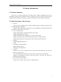
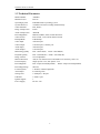
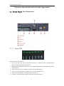
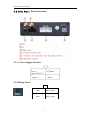
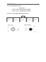
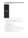
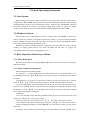
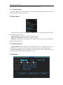
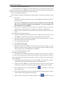
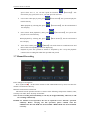
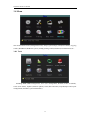
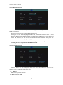
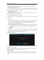
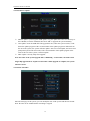
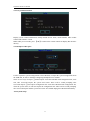
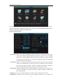
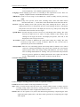
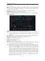
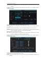
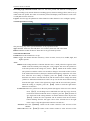
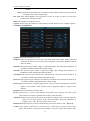
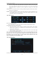
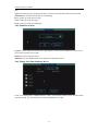
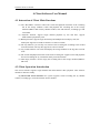
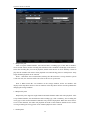
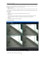
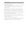
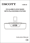
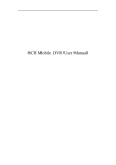
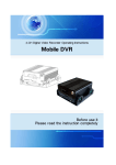
AK54 Pro Tracker User Manual AK54 Pro Tracker User Manual AK54 Pro Tracker User Manual Contents 1 Product Introduction ..................................................................................................................... 3 1.1 Product Summary ..................................................................................................... 3 1.2 Main Functions of the Product.................................................................................. 3 1.3 Technical Parameter .................................................................................................. 4 2 Structure Introduction of the Product Appearance ........................................................................ 5 2.1 Front Panel Port Instruction ...................................................................................... 5 2.2 Back Panel Port Instruction ...................................................................................... 6 2.3 Remote Control Instruction ...................................................................................... 8 3 System Operating Instruction ....................................................................................................... 9 3.1 Start System .............................................................................................................. 9 3.2 Shutdown System ..................................................................................................... 9 3.3 Basic Operation Instruction of Menu........................................................................ 9 3.3.1 Enter Menu Mode .................................................................................................. 9 3.3.2 Menu Component Instruction ................................................................................ 9 3.3.3 Exit Menu Mode .................................................................................................. 10 3.4 Main Menu ............................................................................................................. 10 3.5 Channel Preview ..................................................................................................... 10 3.6 Playback.................................................................................................................. 10 3.7 Manual Recording .................................................................................................. 12 3.8 Menu ....................................................................................................................... 13 3.8.1 Tools .................................................................................................................... 13 3.8.1.1 HDD Management ............................................................................................ 14 3.8.1.2 User Management ............................................................................................. 14 3.8.3 PTZ Control ................................................................................................ 24 3.8.4 Log Information .......................................................................................... 24 3.8.5 Shutdown System ........................................................................................ 25 3.8.7 Bus Information .......................................................................................... 26 3.8.8 Overlay Setting ............................................................................................ 26 4 Client Software User Manual ..................................................................................................... 27 4.1 Instruction of Client Main Functions ...................................................................... 27 4.2 Client Operation Introduction ................................................................................. 27 5 Frequently Asked Question......................................................................................................... 33 Standalone DVR User Manual 1 Product Introduction 1.1 Product Summary This device is specially designed for the mobile DVR. It adopts embedded processor and embedded operating system, combines the latest technologies in the IT filed like audio and video compression/decompression technology. Its structure adopts special anti-vibration technology. 1.2 Main Functions of the Product Record There are four recording modes: manual recording, timing recording, motion detection recording and alarm recording; Support SATA HDD and SD card storage. The recording file in the HDD and SD card can choose overwrite or don’t overwrite. Preview and playback Support single channel, 4 channel audio and video output; Support partial blind of the image; Support searching file by recording type, start time and end time; Support fast forward, slow forward, single frame and so on when playback; Support displaying local recording status, alarm status and motion detection. Backup Support USB backup function Alarm Local signal value alarm input; Motion detection alarm; Abnormity processing alarm. Security Admin user can create 8 common users at most and set their authorities. You can also delete the common users. User password protection function. User must enter correct password when login. Support log management, provide record and search of the local log, alarm log, abnormal log and remote log. Record of Vehicle Information Support device number and car number recording function. 3 Standalone DVR User Manual 1.3 Technical Parameter Model Number Main Processor Operating System System Resource Video Standard Image Compression Audio Compression Recording Mode Video Search Backup Mode Video Input Video Output Audio Input Audio Output Monitoring Quality Playback Quality Image Control Motion Detection Picture Display Recording Rate Recording Storage Local Playback Alarm Input Storage Port USB Port Ignition Signal Power Supply AK54Pro Hi3512 Embedded Linux operating system 4-channel real-time recording simultaneously PAL, NTSC H.264 ADPCM Manual, schdule, alarm, motion detection. Time search, event search, channel search USB backup 4ch aerial port 1ch aerial port, 1ch lotus port 4ch aerial port 1ch aerial port PAL: 720x576(D1) NTSC: 720x480(D1) PAL: 352x288(CIF) NTSC: 352x240(CIF) 6-level adjustable 396(22×18) detection areas and multi-level sensitivity can be set Single-picture view, four-picture view PAL: 25fps/second (adjustable) NTSC: 30fps/second (adjustable) SD card 1 channel, 4 channel playback 4 switching value 1 USB port, 1 SD port 1 USB1.1 port 1 DC 8V~32V 4 Standalone DVR User Manual 2 Structure Introduction of the Product Appearance 2.1 Front Panel Port Instruction 2.1.1: Status LED Indicator definition instruction: Power: the power led will turn red when the power is connected; after soft-shutdown the device, the power led will become green. RUN: this led will flash when the device is working properly; after soft-shutdown the device, it will turn off. Alarm: when there is any channel alarm input, this led will turn on. Video loss: where there is any channel video loss, this led will turn on. Record: when the HDD is recording, this led will turn on. SD card: when the SD card is detected, the SD card led will turn on. 5 Standalone DVR User Manual 2.2 Back Panel Port Instruction 2.2.1 : Power Supply Interface 2.2.2:Debug Serial GND RS232_RXD GND RS232_TXD 6 Standalone DVR User Manual 2.2.3: I/O Signal Interface Unit 2.2.4:Video- Audio Input And Output Interface Video-Audio output 1CH Video-Audio input 2CH Video-Audio input 7 3CH Video-Audio input 4CH Video-Audio input Standalone DVR User Manual 2.3 Remote Control Instruction Instruction of some buttons: 1. Power: used to shutdown the system. It will go into effect after long-pressing 5 seconds. 2. FN: a) used to select specified file in the recording file list, in order to backup file. b) used to switch the input method of the soft keyboard. c) change the selected status in the motion detection area setting and blind area setting. 3. MENU: a) call out main menu b) used to exit the soft keyboard c) used to clear all the area setting 4. MULTI: used to set 4-picture view 5. SHIFT: used to display/hide control bar when playback. 6. ESC: exit menu. 7. ●: enter manual record setting interface in order to set manual record. 8. Play (in the middle of the fourth line counted from the end): used to enter the file and search page in order to play recording file. 9. VOIP: the shortcut of the backspace key in the soft keyboard; select all when set motion detection setting area. 10. MUTE: sound/mute setting when playback. 11. OK: when there is no menu, press OK key to display system information. 8 Standalone DVR User Manual 3 System Operating Instruction 3.1 Start System When connect 12V DC power supply to the device, the system starts. After the system start-up completely, the 【POWER】 indicator will become green, and the RUN indicator will be flashing continually. There are three ways of starting the system: 1. long-press the 【POWER】 button on the remote control for 5 seconds; 2. the ignition signal of the vehicle; 3. system sets timing starting system. Note: the system will auto shutdown when unplug the lock of the HDD. 3.2 Shutdown System There are three ways of soft-shutdown system: 1. long-press the 【POWER】 button on the remote control for 5 seconds; 2. the ignition signal of the vehicle; 3. system sets timing shutdown system. Through necessary processing, after about 5 seconds, the system will shutdown and the power led will turn off and the run led will turn on. Shutdown system by power disconnection: unplug the 12V power input, the system will stop working. As unplug power directly may affect the HDD and SD card, we suggest you soft-shutdown the system before unplugging the power. 3.3 Basic Operation Instruction of Menu 3.3.1 Enter Menu Mode Enter the system menu by pressing the 【MENU】 button on the remote control or clicking the right mouse button. 3.3.2 Menu Component Instruction Menu component units mainly include: (1) Check box: “√” means valid, blank means shield. There are two operating modes: 1. use the 【OK】 button or the 【↑】, 【↓】 button on the remote control; 2. click the left mouse button to operate. (2) Selection box: provide two or more than 2 options, but only one option can be selected. Press the【↑】, 【↓】 button on the remote control or click the left mouse button to switch. (3) List box: display the search result information in the list. You can select one item from list. If you press the 【OK】 button or click the left mouse button, the recording file will play; if press the number “0” or the 【FN】 key or the right mouse button, you can select/cancel the recording file in order to backup the recording file. (4) Edit box a) You can switch the input character including number, uppercase and lowercase letters and mark by the 【FN】 key on the remote control. b) You can move the cursor position by the 【←】, 【→】key on the remote control. c) You can delete the character before the cursor by the 【viop】 key on the remote control. d) After completing the input, press the 【MENU】 key on the remote control, you can exit the edit status. (5) Button: used to conduct a specific function or enter the submenu. Press the 【OK】 key on 9 Standalone DVR User Manual the remote control or click the left mouse button to enter the submenu. 3.3.3 Exit Menu Mode Press the 【ESC】 key on the remote control or click the right mouse button, you can exit the menu mode and switch to preview mode. 3.4 Main Menu The menu box will pop-up when press the 【MENU】 key or click the right mouse button. This menu includes three parts. Channel preview: single-picture switch, four-picture preview. Shortcut operation bar: video playback, manual recording. Menu bar: click and enter the submenu which includes Tools, Setup, PTZ, Log, ShutDown, timing, BusInfo and Overlay. 3.5 Channel Preview Single-channel Preview: single-click the left mouse button, you can single-picture preview; press number 1-4 on the remote control, you can single preview the corresponding channel. Four-channel preview: press the 【Multi】 key on the remote control or single-click the left mouse button, it can return to four-picture preview status. 3.6 Playback 10 Standalone DVR User Manual 1. Enter the playback operation interface For four-channel preview interface, press the 【PLAY】 key on the remote control; for the main menu interface, press the 【OK】 key on the remote control or click the left mouse button on “Playback” can enter the playback operation interface directly. 2. File search interface instruction: System supports searching recording file by channel number, recording type and start and end time. File search: Search the recording files which meet the search conditions and they will display in the structure list. Note: if the recording files which meet the search conditions are more than 4000 items, the system will only display the first 4000 items. To search the update file, please modify the search condition. Play by time: to playback all the files within a specified time period, you can select single channel or multi-channel. You can playback 4 channels using this button. Backup by time: backup all the files within a specified time period to the specified device. 3. File search results interface instruction: Playback the specified file: left click the left mouse button on the specified file or click the 【OK】 button on the remote control, you can playback the specified file. Select All: used to fast select all the recording files on the current page (“√” will be shown after selection) in order to backup files. Prev: jump to the previous page Next: jump to the next page Goto: go to the specific page Backup: you can use the 【FN】 key on the remote control or the number “0” or the right mouse button to make a backup mark, backup the selected recording file in the current list box to the corresponding device (USB disk). Cancel: return to the previous page. 4. Playback operation instruction The buttons on the information bar below the playback screen respectively represent: exit, pause, frame forward, slow forward, fast forward, go to the last section, go to the next section, sound; the other information represents: play speed, real play time, the total time of the recording file. Cancel/display the information tip bar: press the 【shift】 key on the remote control or click the right mouse button will display/cancel the information tip bar. Exit play: press the 【ESC】 key on the remote control or click exit by mouse can exit the play screen at any time; it will auto exit the play screen when the file is finished. Pause/continue play: press the 【Pause】 button pause/continue play. Frame forward: under the pause mode, each click the frame forward button, it will play 1 frame forward, namely single frame mode play. Adjust the play speed: press the 【Slow Play】 button 11 on the remote control can will reduce the play Standalone DVR User Manual speed. There are 1/2, 1/4, 1/8 time speed for selection; 【Fast Play】 will increase the play speed, there are 2, 4, 8 time speed for selection. Last section: when play by time, press 【Last Section】, the system will play the last file directly. When playback by selecting file, press 【Last Section】, the file will backward 10% and play. Next section: when playback by time, press 【Next Section】, the system will play the next section directly. When playback by selecting file, press 【Next Section】, the file will forward 10% and play. Turn off/on sound: press there will be corresponding sound icon displaying. Playback by time: the operation is similar to “Playback by file” except the playback content is the recording file within the specified time period. 【MUTE】can switch between sound and mute and 3.7 Manual Recording Enter manual record interface Press 【Record/●】 on the remote control or click “Manual Record” by mouse can enter the manual record interface directly. Manual record interface instruction The manual record operation interface is consists of the following components: channel, status, start/stop icon mark, Start All, Stop All and Exit. Note: for the recording started manually, it can only be stopped manually, otherwise, it will be recording continuously. Remind: for manual record operation, the user is required to have “Record” operation authority. Before carrying out this operation, please confirm with the administrator that the DVR has been installed a HDD which has been formatted correctly. 12 Standalone DVR User Manual 3.8 Menu The menu includes Tools (management tools), Setup (system setup), PTZ (PTZ control), Log (log search), ShutDown (shutdown system), Timing (timing switch), BusInfo (bus information) etc.. 3.8.1 Tools Including HDD (HDD management), User (user management), Default (restore to default), Clear (clear alarm), Update (software update), Time (date and time), Export(import and export configuration) and Info (system information). 13 Standalone DVR User Manual 3.8.1.1 HDD Management Check the current status, capacity and the remaining space of the specified HDD and if the HDD was formatted. Format: used to format the specified HDD or the SD card. Unplug the SD card: before unplugging the SD card, uninstall the software in order to avoid damage to the SD card or SD data; clicking for unplugging the SD card, it has to be unplugged within 10S, otherwise, the SD card will be auto mounted after 10S. Note: the system will restart when the SD card is unplugged illegally. Note: 1. the new HDD or SD card installed can only be used after being formatted; 2. the recording has to be stopped before the HDD formatted. 3.8.1.2 User Management Add user, delete user and modify user. (Other users except the Admin user don’t have the authority to set the authorities of the other users) Add User Enter “User” operation interface. 1. Input New User Name 14 Standalone DVR User Manual On the “User” interface, click “Add”, enter “Add/Modify User” interface, input a new user name (like user), input type supports number, uppercase and lowercase letters and Chinese. 2. Setup Password for the New User On the “Add/Modify User” interface, click “Password” button, enter the password setup interface, input new password directly (password is 6 or less than 6 digits), then confirm password. The password will become valid after confirmation. 3. Setup Rights for New User On the “Add/Modify User” interface, mark “√” means that the user can use this right while blank means that the user cannot use this right. 4. Save the Setup Information of the New User After confirmation, the setup information of the new user will be saved; cancel means give up modification. Modify User Enter the “User” operation interface, click left mouse button or press the 【↑】 【↓】 【OK】 button on the remote control to select the user which needs to be modified in the user selection box, click the “Modify” button, enter the user modification interface, you can modify user password and operation authority. Note: admin administrator can modify the rights of the other users, while the non-admin users can only modify their own login password but cannot add, modify or delete user right. Delete User Enter the “User” operation interface, click left mouse button or press the 【↑】 【↓】 【OK】 button on the remote control to select the user which needs to be deleted in the user selection box, click the “Delete” button to delete the specified user. 3.8.1.3 Restore to Default Restore the system configuration parameter to factory configuration, the system will auto restart when the restore is complete. Note: the vehicle information will not be restored to factory configuration after restoring to default, facilitating the user to save the vehicle information. 3.8.1.4 Clear Alarm Manually clear all the alarm output. When the alarm is cleared successfully, the system will prompt “Alarm has been cleared successfully”, confirm and return to the page of management tools. 15 Standalone DVR User Manual 3.8.1.5 Software Update Manual update: system supports USB update: copy the update file to the root directory of the USB disk, insert the USB disk, then click “OK” to upgrade the system manually. Auto update: insert the USB disk with upgrade file first, when the system restarts, it will detect the update program. If the version number of the update program is different from the one in the system, the system will auto update. After successful update, the buzzer will prompt and system will auto restart; if the version number of the update program is the same as the one in the system, it will not update. MCU update: can only adopt auto upgrade. Note: the name of the system upgrade file is “MDVRB_v version. Bin”; the name of the single chip upgrade file is “mpanel version. Bin”. When upgrade is complete, the system will auto restart. 3.8.1.6 Date and Time Enter the time page of the system, you can modify the time of the system and the time format. Note: the time can be modified when recording is stopped. 16 Standalone DVR User Manual 3.8.1.7 System Information Display system related information, mainly include device name, model number, MCU model number and software version. Note: under preview mode, press 【OK】 button on the remote control can display this interface directly. 3.8.1.8 Import and Export Used to export the system configuration to the USB disk, or import the system configuration from the USB disk, in order to facilitate configuring multiple devices in batch. There are two ways of import: ①manual import: insert the USB disk with configuration file, click OK, after successful import, the system will restart. There will be sound prompting after successful import. ②Auto import configuration file: insert the USB disk with configuration file, when the system starts, it will auto import the configuration file. There will be sound prompting after successful import and the system will restart. You should unplug the USB disk immediately. 3.8.2 System Setup 17 Standalone DVR User Manual System setup includes Setup (system parameter), Record (recording setup), Image (image setup), Alarmin (alarm input), Schedule (schedule setup), Expection (expection handling), MTD (motion detection), PTZ (PTZ configuration) and Network. 3.8.2.1 System Parameter Overwrite: Select “Yes”, when the HDD or SD card is full of recording, the system will overwrite the earliest video information to achieve the purpose of cycle recording. Select “No”, when the HDD or SD card is full of recording, the system will not record any more; at this time, you can choose warning processing when the HDD is full in the menu of “Expection”. Lock Time: If there is no operation within the keypad lock time, the system will cancel the current user automatically. To operate, you need to relogin the system. The lock time can be: 1 minute, 2 minutes, 5 minutes, 10 minutes, 20 minutes, 30 minutes. If auto locking keyboard is unnecessary, then you can choose “Never”. Auto Switch: It shows the time interval of single channel cycle switch in preview. There are: 5 seconds, 10 seconds, 20 seconds, 30 seconds, 1 minute, 2 minutes, 5 minutes and don’t switch options. Standard: used to set the image format, PAL or NTSC, and it is default to PAL format. Transparency: When the user enters the menu operation interface, he can adjust the 18 Standalone DVR User Manual transparency between preview image and the menu by adjusting the level of the menu transparency. Low, middle, high and opacity can be set. Language: Menu language type can be set according to the requirement of user. There are English, simplified Chinese and Traditional Chinese options. ToDisk(Sec): Used to set how long to write HDD once, which is mainly used for protecting HDD. Show Status: Setup if the preview screen show recording mode, status and enable motion detection mark and “√” means show status while blank means status not shown. Preview: setup the display screen after preview delay after starting the device. There are single-picture preview or four-picture preview. (After starting, the device will display four-picture screen, the device will display the screen set up after preview delay and this function will not realize after user login. QUAD Delay: Set how long the preview screen set up will display after starting. The value between [0--600] can be set (unit is second), default to 20S, namely, when starting but not login, the device will display four-picture, after 20S, it will display the screen set up in “Preview”. ACC Delay: Used to set when to shutdown the system after setting ACC staling. The value between [0--255] can be set (unit is minute). When set 255, even the state is ignition, the system will not shutdown. Startup Mode: There are ACC and timing options. The startup mode is default to ACC. When select ACC starting and shutdown, the system can be started once receiving the ignition signal; when select timing starting and shutdown, you need to set the time of starting and shutdown in “Timing”. The system will start only when the time set up arrives, and there is nothing related to the ACC signal. You can also use the 【POWER】 key on the remote control to start the device. 3.8.2.2 Recoding Setting Used to configure recording parameters which are explained as follows: Channel: Choose the number of the target channel to be set up. Type: There are main stream and sub stream for selection. Main stream is mainly used for recording setting while sub stream is mainly used for compressing bit stream during network transmission in order to lighten the hardware burden. Stream: There are two options: A/V (refer to the data stream generated by compressing the video signal and audio signal) and V (the data stream generated by compressing the single video signal) 19 Standalone DVR User Manual CBR/VBR: There are VBR and CBR options. When set VBR, you can configure the image quality. BitRate: There are 128Kbps, 256Kbps, 512Kbps, 1Mbps (unit is bps) options. The specific limit size of the bit rate will be adjusted according to the scene and the camera condition and the requirement on the image quality. FrameRate: Full frame rate (PAL 25f/s, NTSC 30f/s), 20f/s, 15f/s, 10f/s, 5f/s, 2f/s, 1f/s. Resolution: When set VBR, you can set the image quality. CopyTo: Used to copy the parameters of this channel to other channel so as to configure quickly. 3.8.2.3 Image Setting Channel: Select the number of the target channel number to be set up. Name: Used to modify the name of the channel (cannot be copied). It supports numbers, uppercase and lowercase letters, Chinese and common used marks, up to 12 characters at the most. Show Name: Used to set if show the channel name and the position of the channel name shown. Show Time: Used to if show the time and the show position when preview. Brightness: Set the brightness of the image. Contrast: Set the contrast of the image. Hue: Set the hue of the image. Saturation: set the saturation of the image. Blind: In the area which needs to be blinded, you can set “Blind”. When mark “√”, the blind area setting button will be actived and enter the blind area setting interface. Area: On the blind area setting interface, a small yellow box will appear in the middle of the area namely blind setting box. Area Creation: move the yellow box to the start position of the setting area; using the 【FN】 key on the remoye control (yellow box and red box can switch) to change it into red box (red box is the motion detection area); then adjust the size of the area by direction buttons: after completing the adjustment of the area, press the 【FN】 key, this motion detection area will be selected and saved and the small red box will become small yellow box. There are 4 blind areas can be set up at the most. Click the left mouse button and drag from the left upper corner to the right lower corner, the blind area will be generated. After the setting is complete, press the 【OK】 button or click the right mouse button to exit and save. 20 Standalone DVR User Manual Clear All: Press the【MENU】 key on the remote control to clear all the blind areas of the channel. CopyTo: Used to copy the parameters of this channel to other channel so as to configure quickly. 3.8.2.4 Alarm Input Input: Select the number of the target channel number to be set up. Type: According to actual conditions, set if the alarm input is valid when choose High Volt orlow Volt. PTZ: First select the channel number, set one of the linkage settings: preset, cruise, track. Duration: When the alarm input is complete, set up the delay time needed for dealing with buzzer, video, recording etc.. There are 5sec, 30sec and 1min options. Buzzer: Whether to trigger the buzzer alarm. Rec. CH: Setup which channels to be triggered to record when there is alarm input. To record, you have to set the time periods in the schedule interface. CopyTo: Used to copy the parameters of this channel to other channel so as to configure quickly. 3.8.2.5 Schedule Setting Used to set the time periods of timing recording, motion detection and alarm input recording. Channel: Select the channel which needs to be set. Week: Select the target day, you can set respectively any day from Monday to Sunday or set unifiedly. 21 Standalone DVR User Manual Recording Type and Time Period: There are four time periods and different recording types, timing recording (red), motion detection recording (green), alarm recording (yellow) can be set up within each time period. The status of each time period will display at the bottom as well as the overall plan from 0 to 24 hours. CopyTo: Used to copy the parameters of this channel to other channel so as to configure quickly. 3.8.2.6 Expection Processing The processing way of the system when there is any expection occurs. Type: Includes video loss, disk full (don’t set overwrite), disk error and video blind. Buzzer: Whether enable the buzzer when there is any specified expection. 3.8.2.7 Motion Detection Channel: Select the channel to be set up. Sensi.: Trigger the motion detection sensitivity. There are none, lowest, low, middle, high, and highest options. Area: Blind: On the setting interface of motion detection area, a small yellow box appears in the middle of the area namely area setting box. Area creation: first move the yellow box to the start position of the setting area, use the 【FN】 button on the remote control (the yellow box and the red box can switch) to change it into small red box (red box is the motion detection area); then press the direction buttons to adjust the size of the area; when the area setting is complete, press the 【FN】 button, the motion detection area will be selected and saved, and the small red box change into small yellow box. Maximum 4 blind areas can be set up. Use the left mouse button to drag from the left upper corner to the right lower corner and the area will auto generate. When the setting is complete, press the 【OK】 button or click the right mouse button to exit and save. Local Clear: Move the yellow box to the start position (left upper) of the area to be cleared. Press 【FN】, it will change into a small black box (the area to be cleared), local will be cleared. When the clear is complete, press the 【OK】 button to save and return to the setting interface of motion detection menu. If press the 【ESC】 button, the clear operation will be invalid. Click the left mouse button and drag from the left upper corner of the selected area to the right lower corner. Click the right mouse button to exit and save. All Clear: Press the 【MENU】 button on the remote control to clear all areas of the channel. Select All: Press the 【VOIP】 button on the remote control to select all areas of the 22 Standalone DVR User Manual channel. Delay: When the motion detection is ended, how long will the related processing (such as recording, buzzer, alarm output) delay. Rec. CH: Setup which channels to be triggered to record. To record, you have to set the time periods in the schedule interface. Buzzer: Set whether to enable the buzzer. CopyTo: Used to copy the parameters of this channel to other channel so as to configure quickly. 3.8.2.8 PTZ Configuration Channel: Select the channel to be se t up. Baudrate: There are eight kinds of rates: 300, 1200, 2400, 4800, 9600, 19200, 38400, 57600 and 115200 in the serial port. The selected item should be in accordance with the matched PTZ rate setting. Data Bit: The protocol types include 6 digits, 7 digits and 8 digits. The selected item should be in accordance with the matched PTZ data bit setting. Stop Bit: The protocol types include 1 digit and 2 digits. The selected item should be in accordance with the matched PTZ data bit setting. Checksum: The protocol types include none, odd and even. The selected item should be in accordance with the matched PTZ checksum setting. Flow Ctrl: The protocol types include none, hardware, Xon/Xoff. The selected item should be in accordance with the matched PTZ flow control setting. Protocol: The protocol types currently supported are: Pelco-p, Pelco-D, Samsung, b01. With the update of the software, more decoders will be supported. Please be subject to the software.. Decoder: Refer to the address of the decoder. Preset: Preset point is to preset and memorize the position, focus, aperture and zoom of the camera and use a number to identify these settings at the same time. Add Preset: Input a preset point in the preset point edit box, ranging from 1-128, then adjust the camera to the target position by the direction button. When the adjustment is complete, press “OK”, the preset point will be saved. Delete Preset: Input a preset point to be deleted in the preset point edit box, click 【Delete】. Cruise: Cruise path is a path where a camera runs at a certain speed. It passes various cruise points with numbers. Each cruise point includes stay preset points and retention time. 23 Standalone DVR User Manual Thus, the settings of the cruise path include the parameter settings of the cruise point, preset point, retention time and cruise time etc, then enter “set” to set the cruise path and cruise path number. At present, one device supports the setting of 16 cruise path numbers. Track: Track is a line which is used to record the predefined irregular movement of the camera. Enter “Set” to set the track. CopyTo: Click the application to button at the bottom, apply the current configuration to the corresponding channel (selected channel). (need to click 【OK】 button to save, click 【Cancel】 button to exit without saving. 3.8.3 PTZ Control Enter the PTZ control Interface Press the【PTZ】button on the remote control or click the left mouse button to enter; The introduction of the PTZ Control function The main operations of PTZ Control are: direction control; rotation; zoom control; adjust the focus; adjust the iris. In addition to the rotation function, other four options can choose the control speed. Switch the page to invoke the preset point; start/stop auto cruise; wiper control; light control; auxiliary equipment control. Note: The invoked preset point must have been set up. For the setting method of the cruise path, please refer to the cruise path number setting in 3.8.2.9 PTZ setting. When the cruise path number set up is less than 2 digits, you need to add 0 to fill up 2 digits before the value of the corresponding cruise path number set up. 3.8.4 Log Information Search the log information record in the device according to the log type and the start and end 24 Standalone DVR User Manual time. Type: Select the log type, including all, alarm, expection, local operation and remote operation. Start/End: Set the start and end time of searching log. Prev: Used to go to the preview page. Next: Used to go to the next page. Goto: Used to go to the specified page. 3.8.5 Shutdown System Logout: Used to cancel the current user. After logout, if you want to continue to use the device, you need to login the system again. Restart: Used to restart the device. Shutdown: Used to shutdown the device namely soft shutdown device. 3.8.6 Timing Start and Shutdown Device Used to set timing start or shutdown device. There are four time periods can be set and within each time period, you can set the time of start and shutdown every day. 25 Standalone DVR User Manual 3.8.7 Bus Information DeviceID: Used to set the ID number of every device. DeviceName: Used to set the device name which is the same as the device name set up in “Info”. BusNo: Used to set the bus number of the vehicle, facilitating management. Note: All information in this item can’t be restored to the factory setting, but you can manually modify the relevant information. 3.8.8 Overlay Setting Preview: Used to set up whether to display time, channel number, bus number and if there is flashing prompting when video loss under preview mode. “Open” means display this item when preview while “Close” means not display this item on the interface when preview. Recording: Used to set up whether to display time, channel number and bus number in the recording file. “Open” means display this item in the recording file while “Close” means not display this item in the recording file. 26 Standalone DVR User Manual 4 Client Software User Manual 4.1 Instruction of Client Main Functions (1) The “RecordFile” interface realizes the search and playback functions of the recording file in the storage medium: search and playback the recording file in the storage medium (HDD or SD card) by channel number, start and end time, recording type and car number. (2) Playback function: support single channel playback by file and time; support multi-channel playback by time. (3) Backup function: support single file backup and multiple files backup by time; the backup file supports two kinds of formats: ifv and avi formats. (4) File clip function: you can clip one section of the recording file according to the needed start and end time. The clip file supports ifv and avi formats. (5) Log search function: can search and display the storage medium or the log files stored in local. (6) The search and playback function of the local recording file: support search and playback the local recording file by car number and by start and end time. (7) Data empty function: used to empty the recording files in the storage medium (HDD or SD card). 4.2 Client Operation Introduction This client software supports single-channel and multi-channel video playback. This software includes 4 interfaces totally. (1) Record file search interface: the system supports search recording file by channel number, recording type, start and end time and car number. 27 Standalone DVR User Manual 1.1 Playback by file After set up the channel number, start and end time, recording type (event) and car number, click “Search” button, all the recording files which meet the conditions will display in the list box. Select the recording file you want to playback, double-click this file or click “FilePlay” button to play this file. Double-click mouse when playback can switch the big picture to small picture. Only single-channel playback can be realized. Note 1: “StartTime” has record function, namely, after the start time is set up, when the system is run next time, the start time will be the same as the one set up last time. Note 2: When search the “Car Number” in the storage medium, all the car numbers will display in the drop-down list box. The car numbers in the drop-down list box will be updated after changing the storage medium. 1.2 Playback by time Playback by time supports single-channel and multi-channel audio and video playback. After set up channel number, start and end time and recording type, click “TimePlay”, the recording file of any type of the selected channel within this time period will playback. When the mouse moves to one of the channels, the audio will playback the audio of this channel; double-click to realize viewing recording file in big picture. Four channel playback can be realized. 1.3 Backup File 28 Standalone DVR User Manual Select the recording file which you want to backup from the list box, then click “BackupFile” button, select the storage path to backup. When the backup is complete, there will be a succeed prompting. The backup file can be with ifv and avi format. 1.4 Backup by Time: After set up the channel, recording type and the start time and end time of the file, click “BackupByTime, realize multi-file backup at the same time. Setup the backup path and type in the “Set” interface. 1.5 Setting: This function is used to set the backup path and backup type of the file. 1.6 Empty Data: This function is used to empty the recording file in the storage medium (HDD or SD card) Note: The data will not be able to be restored after empty. Please use it cautiously. 1.7 Language: This software supports Chinese and English. (2) Playback Interface: When the mouse points to the icon, the functions of this icon will display. 2.1 Stop: Click “Stop” button to stop the file play. 29 Standalone DVR User Manual 2.2 Pause, Frame Forward: “Pause” button controls pause or play recording file; frame forward: each click will play one frame forward. 2.3 Playback Speed: It can play in normal speed (1 time), fast forward (2 times, 4 times, 8 times, 16 times), slow forward (1/2, 1/4, 8, 1/16). 2.4 Normal Speed: When click fast forward or slow forward, to restore to the normal speed directly, click this button. 2.5 Video Cut: To cut any section of the video, click “Cut” button, another progress bar will appear under the play progress bar. Click the right mouse button on the needed position on the progress bar can “Add Cut Point”, “Cancel Cut Point”. When two cut points are set up, you can “Backup Cut Video” (When the video file cut is separated into two files according to the start time and end time, there will be two files generated; and so on). Note: when the interval between the start time and the end time is relatively big, but the time interval of the video which needs to be cut is relatively small, two cut points will overlap together which will not affect the cut function. 2.6 Snapshot: Capture the image of any time selected by the user. 2.7. Open File: This function is used for single-channel playback the recording file in the PC end. (3) Log Interface: System supports search log by type and start time and end time. 30 Standalone DVR User Manual 3.1 Browse: Used to setting the path of the log file (log.bin), click “Search Log” to view the log file. Without setting the path, it will default to search the current log information in the storage medium. 3.2 Type: Include all, alarm, exception, local operation and remote operation. Select the type of the log you want to search. 3.3 StartTime and EndTime: Set the start time and end time of the log you want to search. (4) Local Recording Search Interface: Used by the recording files of the car number and time search saved in local. . 31 Standalone DVR User Manual 4.1 Browse: Used to set the file which save the recording files in local. 4.2 Search: Select the car number and the start time and end time which you want to search, click “Search” button, all the recording files of a vehicle within a time period will display in the list box. Note: “StartTime” has record function, namely, after the start time is set up, when the system is run next time, the start time will be the same as the one set up last time. 4.3 NativePlay: Setup the path, car number, start time and end time, click “NativePlay” button to play the recording file within this time period by time. 32 Standalone DVR User Manual 5 Frequently Asked Question 1. How to operate the motion detection recording? A: There are mainly two steps for setting the motion detection recording: Set the sensitivity, area and the recording channel to be triggered of the corresponding channel in the “MTD” page. Set the time of the corresponding channel triggering the motion detection recording in the “Schedule” page. Note: the alarm recording setting is similar to the motion detection recording setting. You need to set the recording channel in the “Alarmin” page, and set the time in the “Schedule” page. 2. How to modify the information in the edit box when use remote control? A: Use 【FN】 to switch the type of the input character; use the 【MENU】 key to exit the edit mode after edit is complete. 3. After connect the HDD and start the recording, why doesn’t it record? A: There are three possibilities: When the HDD connected is new, it cannot record without format. Thus, you need to format the new HDD first; When set overwrite when the device is full in the “Setup” interface, the device will stop recording when the HDD is full; When the HDD connected is defective, it will not record while the system can preview. 4. Why can’t the SD card be formatted? A: When the capacity of the SD card is less than 4G, it cannot be formatted. 5. Why can’t the connected mobile HDD or the U disk backup? A: When the file system format of the mobile HDD or the U disk is NTFS, they cannot backup. 6. Why sudden shutdown occurs sometimes? A: When ACC is under stalling status, up to the time set of “ACC Delay”, it will auto shutdown. 7. Why does the device will auto start after shutdown? A: When conduct soft shutdown, ACC is still under ignition status, thus the device will auto start after shutdown. 8. Why doesn’t the device shutdown immediately after stalling? A: There is “ACC Delay” setting in the “Setup”, which default to 5 minutes, namely, it will shutdown after 5 minutes since receiving the ignition signal; to shutdown immediately after stalling, you only need to set the time of “ACC Delay” to be 0. 9. Why is there only audio but no video when the client plays the recording file? A: Because the DirectDraw acceleration is not enabled. The enable method is: input dxdiag in the running interface, open DirectX diagnostic Tool, select “Show”, “Enable” the DirectDraw acceleration in the DirectX function. It is shown as the below picture: 33 Standalone DVR User Manual 34