1
Schlumberger ITS 9000PX/MX
Schlumberger ITS 9000PX/MX
Subroutine Memory Option
User Manual
740018904 / Rev 01
Copyright© 1989 - 1994
Schlumberger Technologies, Inc.
All rights reserved
Publication Number - 740018904 / Rev 01
Printed in France
Jul 1994
Schlumberger Technologies maintains a policy of constant product improvement. The
information contained with in this document may be subject to change without notice.
No part of this publication may be reproduced, or copied, without the express permission
of Schlumberger Technologies. Additional copies of this, and any other publication, may
be obtained from your local sales office.
A reader feedback form is provided at the end of this publication. Your suggestions and
comments would be appreciated.
The following are trademarks of Schlumberger Technologies
ASAP™
Sequencer Per Pin™
The following are trademarks of AT&T Bell Laboratories
UNIX
The following are trademarks of Digital Equipment Corporation
MicroVAX
DECnet
VMS
The following are trademarks of Sun Microsystems Inc.
Sparcstation
The following are trademarks of Xerox Corporation
Ethernet
ii
Schlumberger ITS 9000PX/MX Subroutine Memory Option User Manual - 740018904 / Rev 01
Schlumberger ITS 9000PX/MX
Table of Contents
Table of Contents................................................................................................................................. iii
List of Figures ....................................................................................................................................... v
Preface................................................................................................................................................. vii
Overview ................................................................................................................................ vii
Intended Audience ................................................................................................................. vii
Terms and Abbreviations........................................................................................................ vii
Conventions .......................................................................................................................... viii
Related Publications.............................................................................................................. viii
1
2
Installation.......................................................................................................................................... 1-1
1.1
Prerequisites ........................................................................................................................ 1-1
1.1.1
Hardware............................................................................................................... 1-1
1.1.2
Software ................................................................................................................ 1-1
1.2
Hardware Installation............................................................................................................ 1-1
1.2.1
Subroutine Memory Card Locations in the C-Crate .............................................. 1-2
1.2.2
Subroutine Memory Card Locations in the H-Crate .............................................. 1-2
1.3
Software Installation ............................................................................................................. 1-3
1.4
Testing.................................................................................................................................. 1-3
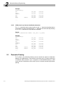
Subroutine Memory Programming................................................................................................... 2-1
2.1
Subroutine Structure ............................................................................................................ 2-1
2.1.1
Operand Size Selection ........................................................................................ 2-2
2.2
Subroutine Memory Instructions........................................................................................... 2-2
2.2.1
INC (Increment) Instruction ................................................................................... 2-3
2.2.2
HALT Instruction.................................................................................................... 2-3
2.2.3
RET (Return from Subroutine) Instruction............................................................. 2-3
2.2.4
RPT (Repeat) Instruction ...................................................................................... 2-4
2.2.5
RPTM (Repeat Until Match) Instruction ................................................................ 2-4
2.2.6
RPTC (Repeat Continuous) Instruction................................................................. 2-4
2.2.7
CALL (Call Loop Subroutine) Instruction............................................................... 2-5
2.2.8
CALLZ Instruction ................................................................................................. 2-6
2.2.9
CALLC (Call Continuous Subroutine) Instruction.................................................. 2-6
2.2.10 CALLM (Call Match Subroutine) Instruction.......................................................... 2-7
2.2.11
GOTO (Goto Subroutine Location) Instruction...................................................... 2-8
2.2.12 GONZ (Go on Not Zero to Subroutine Location) Instruction ................................. 2-8
Schlumberger ITS 9000PX/MX Subroutine Memory Option User Manual - 740018904 / Rev 01
iii
Table of Contents
2.2.13
2.2.14
2.2.15
iv
GOCL (Go Continuous to Subroutine Location) Instruction .................................. 2-9
LDC (Load Loop Counter) Instruction ................................................................... 2-9
LDCH (Load Loop Counter Conditional) Instruction ............................................ 2-10
2.3
Parameter Passing ............................................................................................................. 2-10
2.4
Match Modes ...................................................................................................................... 2-13
2.4.1
Fast Match Mode................................................................................................. 2-13
2.4.2
Immediate Match Mode ....................................................................................... 2-14
2.4.3
Match Mode Programming .................................................................................. 2-14
Schlumberger ITS 9000PX/MX Subroutine Memory Option User Manual - 740018904 / Rev 01
Schlumberger ITS 9000PX/MX
List of Figures
Figure 1.1
Figure 1.2
Figure 2.1
Subroutine Memory Card Installation in the C-Crate....................................................... 1-2
Subroutine Memory Card Installation in the H-Crate....................................................... 1-3
F_Data Source Selection Block Diagram ...................................................................... 2-11
Schlumberger ITS 9000PX/MX Subroutine Memory Option User Manual - 740018904 / Rev 01
v
List of Figures
THIS PAGE INTENTIONALLY LEFT BLANK.
vi
Schlumberger ITS 9000PX/MX Subroutine Memory Option User Manual - 740018904 / Rev 01
Overview
Preface
Overview
The Subroutine Memory is an option provided for the Schlumberger ITS 9000PX/MX for
test situations that require the execution of repetitive codes or conditional loops to
ensure the device being tested is in a know state. The test data can be sourced from the
either the Subroutine Memory itself or the Main Memory.
The test vectors are written in a similar way to those of the Main Memory. An additional
set of Subroutine Memory specific instructions are provided to simplify complex test
needs.
The Subroutine Memory has 4K memory capacity depth.
Intended Audience
This publication should be used by anyone using the Schlumberger ITS 9000PX/MX
Subroutine Memory option.
Terms and Abbreviations
The following table lists the terms and abbreviations used in this publication.
Table 0.1 List of Terms and Abbreviations
Term/Abbreviation
Meaning
APG
Algorithmic Pattern Generator
ASAP
Advanced Symbolic ATE Programing
DPS
Device Power Supply
ESS
Event Sequence Store.
ESSM
Event Start Sequence Memory.
Left Click
Click on an item with the left-hand mouse button.
MSCM
Main Sequence Control Memory.
PE
Pin Electronics
Schlumberger ITS 9000PX/MX Subroutine Memory Option User Manual - 740018904 / Rev 01
vii
Preface
Table 0.1 List of Terms and Abbreviations
Term/Abbreviation
Meaning
PMU
Precision Measurement Unit
TBD
To Be Defined.
Conventions
The following table lists the conventions used in this user guide to illustrate certain
points.
Table 0.2 List of Conventions
Convention
Meaning
UPPERCASE
Any command in UPPERCASE must be typed on the
system exactly as it is shown in the manual.
lower case
Any procedure parameter in lower case is to be replaced by
a user input required.
[parameter]
Any procedure parameter enclosed in square brackets is
optional. In the case of confusion with a required square
bracket a comment is added.
<USER_INPUT>
User supplied data is indicated by placing its name within
<>.
{comment}
Braces enclose explanatory comments, and are generally
used in examples.
Hex 0F13
A number preceded by the letters ‘Hex’ is in hexadecimal
notation.
Bin 1010
A number preceded by the letters ‘Bin’ is in binary notation.
…
An ellipsis means that either the preceding item can be
repeated, or that lines of a program are supplied by you,
depending on the specific needs of that program.
Related Publications
The following publications provide additional information for some of the topics covered
by this manual. Whenever such information is available a reference to the related
publication is given in the text of this publication.
Table 0.3 List of Related Publications
Part Number
viii
Title
740018905
Schlumberger ITS 9000PX/MX Algorithmic Pattern
Generator User Guide.
740018030
Schlumberger ITS 9000PX/MX Diagnostic Manual
Schlumberger ITS 9000PX/MX Subroutine Memory Option User Manual - 740018904 / Rev 01
Prerequisites
1
1
Installation
This section describes the hardware and software installation procedures for the
Schlumberger ITS 9000PX/MX Subroutine Memory option.
1.1
Prerequisites
Your Schlumberger ITS 9000PX/MX must have the following hardware and software
configurations.
1.1.1
Hardware
Not Applicable
1.1.2
Software
The Schlumberger ITS 9000PX/MX must be running ASAP software version 2.x or later.
1.2
Hardware Installation
The hardware installation of the Subroutine Memory may only be carried out by
Schlumberger Technologies Field Service personnel.
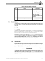
The following table lists the hardware items required for the Subroutine Memory Option
and their crate locations:
Table 1.1 Subroutine Memory Hardware Installation
Description
C-Crate
1
Sub Sequence Instruction Decoder
✔
2
MSCM 4M
✔
2
Subroutine Memory
✔
1
CM Sub Address
✔
1
Subroutine Memory Data Multiplexer per 32 Pins
Schlumberger ITS 9000PX/MX Subroutine Memory Option User Manual - 740018904 / Rev 01
H-Crate
✔
1-1
1
Installation
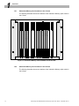
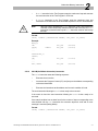
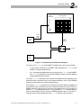
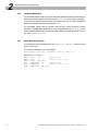
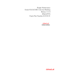
1.2.1
Subroutine Memory Card Locations in the C-Crate
The following illustration shows the locations of the Subroutine Memory option cards in
the C-Crate:
1
2
3
C
/
C
l
o
c
k
B
u
f
f
e
r
5
6
T
e
s
t
T
i
m
e
P
e
r
i
o
d
M
e
s
u
r
e
m
e
n
t
C
/
C
l
o
c
k
G
e
n
e
r
a
t
o
r
4
B
u
f
f
e
r
2
U
n
i
t
7
8
9
D
e
b
u
g
S
e
q
C
o
n
t
r
o
l
S
u
b
I
n
s
t
r
D
e
c
o
d
e
r
10
11
12
13
14
15
16
17
C
/
H
S
I
T
F
M
S
C
M
1
M
S
C
M
3
M
S
C
M
2
S
u
b
S
u
b
4
M
4
M
4
M
M
e
m
2
M
e
m
3
M
S
C
M
4
18
4
M
B
u
f
f
e
r
19
20
21
C
M
S
u
b
A
d
d
r
e
s
s
3
Figure 1.1 Subroutine Memory Card Installation in the C-Crate
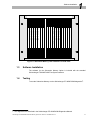
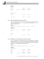
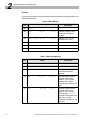
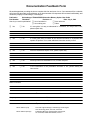
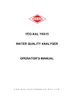
1.2.2
Subroutine Memory Card Locations in the H-Crate
The following illustration shows the locations of the Subroutine Memory option cards in
the H-Crate:
1-2
Schlumberger ITS 9000PX/MX Subroutine Memory Option User Manual - 740018904 / Rev 01
Software Installation
1
2
3
4
5
6
7
8
P
i
n
P
i
n
P
i
n
P
i
n
P
i
n
P
i
n
P
i
n
P
i
n
S
l
i
c
e
S
l
i
c
e
S
l
i
c
e
S
l
i
c
e
S
l
i
c
e
S
l
i
c
e
S
l
i
c
e
S
l
i
c
e
4
M
4
M
4
M
4
M
4
M
4
M
4
M
4
M
9
10
11
12
13
14
15
16
17
18
19
20
21
H
/
H
i
g
h
H
/
C
l
o
c
k
S
U
B
S
U
B
P
i
n
P
i
n
P
i
n
P
i
n
P
i
n
P
i
n
P
i
n
P
i
n
M
E
M
M
E
M
B
u
f
f
e
r
D
A
T
A
D
A
T
A
S
l
i
c
e
S
l
i
c
e
S
l
i
c
e
S
l
i
c
e
S
l
i
c
e
S
l
i
c
e
S
l
i
c
e
S
l
i
c
e
4
M
4
M
4
M
4
M
4
M
4
M
4
M
4
M
M
U
X
M
U
X
S
p
e
e
d
I
T
F
1
Figure 1.2 Subroutine Memory Card Installation in the H-Crate
1.3
Software Installation
The software for the Subroutine Memory Option is included with the standard
Schlumberger ITS 9000PX/MX Test System software.
1.4
Testing
To test the Subroutine Memory run the Schlumberger ITS 9000PX/MX diagnostics1.
1 The diagnostics are described in the Schlumberger ITS 9000PX/MX Diagnostics Manual.
Schlumberger ITS 9000PX/MX Subroutine Memory Option User Manual - 740018904 / Rev 01
1-3
1
Installation
THIS PAGE INTENTIONALLY LEFT BLANK.
1-4
Schlumberger ITS 9000PX/MX Subroutine Memory Option User Manual - 740018904 / Rev 01
Subroutine Structure
2
2.1
2
Subroutine Memory
Programming
Subroutine Structure
The format of a Subroutine Memory programing line is written as follows:
Format:
SUBROUTINE_F;
[<LABEL>] <INSTRUCTION> [<OPERAND>] [<LOPM>] [<+>] [<SCAN>]
[<EINSTn>]
<VEC_DEF> {<F_DATA>)
Parameters:
Table 2.1 lists the parameters of the subroutine structure.
Table 2.1 Subroutine Memory Parameters
Parameter
Description
<LABEL>
The <LABEL> is used by certain instructions, e.g.
CALL, GOTO, GONZ, etc. to identify branch
addresses.
<INSTRUCTION>
The <INSTRUCTION> controls the Subroutine
sequencer.
<OPERAND>
The <OPERAND> is an optional field for the instructions
that require an address or count.
<+>
The <+> instruction token increments the parameter
vector.
<SCAN>
The <SCAN> instruction token increments the serial
scan vector.
<EINSTn>
The <EINSTn> instruction token enables the
Instrument <n>.
<VEC_DEF>
The <VEC_DEF> defines the combination of sequence
names the Pindefs use.
Schlumberger ITS 9000PX/MX Subroutine Memory Option User Manual - 740018904 / Rev 01
2-1
2
Subroutine Memory Programming
Table 2.1 Subroutine Memory Parameters
Parameter
Description
The <F_DATA> field contains the actual vector for the
line, and is written in the same order as the Pindef.
<F_DATA>
Note:
✎
2.1.1
The Subroutine Memory Option provides four additional Enable Instrument
bits.
Operand Size Selection
Without the Subroutine Memory option installed the range of values of the operand can
be from 2 - 4096 (12-bit operand). With the Subroutine Memory option installed this
range is increased to 2 - 65536 (16-bit operand).
By default the 12-bit operand is used. In order to select the 16-bit operand the
OPERAND_16_BITS directive must be specified on the line following the #pattern
pattern_name directive in the pattern file.
2.2
Subroutine Memory Instructions
The Subroutine Memory instructions are of the following categories: incremental,
branching, loading, and control.
Table 2.2 lists the Subroutine Memory Instructions.
Table 2.2 Subroutine Memory Instructions
Applicability
Syntax
2-2
Opcode
Instruction Description
Subroutine
Memory
Main
Memory
INC
0000
Increment
4
4
HALT
0001
Halt
4
4
LDCH
0010
Load Loop Counter
(Conditional)
4
4
LDC
0011
Load Loop Counter
4
4
RPTM
0100
Repeat Until Match
4
4
RPT
0101
Repeat
4
4
RPTC
0110
Repeat Continuous
4
4
CALLM
1000
Call Match Subroutine
CALLZ
1001
Call (Loop) Subroutine
4
4
4
Schlumberger ITS 9000PX/MX Subroutine Memory Option User Manual - 740018904 / Rev 01
Subroutine Memory Instructions
2
Table 2.2 Subroutine Memory Instructions (Continued)
Applicability
Syntax
2.2.1
Opcode
Instruction Description
Subroutine
Memory
Main
Memory
CALLC
1010
Call Continuous Subroutine
4
4
CALL
1011
Call Subroutine
4
4
GONZ
1100
Go On Not Zero to Subroutine
4
GOTO
1101
Goto Subroutine
4
GOCL
1110
Go Continuous to Subroutine
4
RET
1111
Return from Subroutine
4
INC (Increment) Instruction
The INC instruction executes the current line and increments the Program Counter
(PC).
Format:
INC [INSTRUCTION TOKENS] <VEC_DEF> {<F_DATA>}
Example:
SUBROUTINE_F;
INC
VEC_DEF
2.2.2
{001101}
HALT Instruction
The HALT instruction executes the current line and ends the execution sequence.
Format:
HALT [INSTRUCTION TOKENS] <VEC_DEF> {<F_DATA>}
Example:
SUBROUTINE_F;
...
...
HALT
VEC_DEF
2.2.3
{001010}
RET (Return from Subroutine) Instruction
The RET instruction executes the current line and returns to the line following the last
calling instruction. This return can be to either to the Main or Subroutine Memory
depending on where the last call was made from.
Format:
RET <LABEL> [INSTRUCTION TOKENS] <VEC_DEF> {<F_DATA>}
Schlumberger ITS 9000PX/MX Subroutine Memory Option User Manual - 740018904 / Rev 01
2-3
2
Subroutine Memory Programming
Example:
SUBROUTINE_F;
...
...
RET, LABEL
VEC_DEF
2.2.4
{001010}
RPT (Repeat) Instruction
The RPT instruction executes the current line <n> times and increments the Program
Counter (PC).
Format:
RPT, n [INSTRUCTION TOKENS] <VEC_DEF> {<F_DATA>}
Example:
SUBROUTINE_F;
INC
VEC_DEF
RPT, 6
VEC_DEF
2.2.5
{001010}
{111010}
RPTM (Repeat Until Match) Instruction
The RPTM instruction either executes the current line until a match condition is found and
increments the Program Counter (PC) or executes the current line n times, ends the
execution sequence and returns an error message (Debug Mode) if the match is not
found.
Format:
RPTM, n [INSTRUCTION TOKENS] <VEC_DEF> {<F_DATA>}
Example:
SUBROUTINE_F;
INC
VEC_DEF
RPTM, 6
VEC_DEF
2.2.6
{001010}
{111010}
RPTC (Repeat Continuous) Instruction
The RPTC instruction executes the current in a continuous loop and sends an interrupt
signal to the CPU to allow the CPU to execute the next Test Program instruction whilst
the functional test is looping.
There are two methods of stopping the continuous loop, these are:
•
A KILL instruction in the Test Program stops the continuous loop and executes
the next instruction of the Test Program in a DC test.
•
A RESUME instruction in the Test Program stops the continuous loop and
executes the next instruction of the functional sequence in a DC or functional test.
Format:
RPTC [INSTRUCTION TOKENS] <VEC_DEF> {<F_DATA>}
2-4
Schlumberger ITS 9000PX/MX Subroutine Memory Option User Manual - 740018904 / Rev 01
Subroutine Memory Instructions
Example:
SUBROUTINE_F;
INC
VEC_DEF
RPTC
VEC_DEF
2.2.7
2
{001010}
{100110}
CALL (Call Loop Subroutine) Instruction
The CALL instruction can be made from the Main or Subroutine.
From the Main the CALL instruction starts the following sequence:
•
Executes the current line.
•
Increments the Program Counter (PC) and jumps to the subroutine address
corresponding to the associated label.
•
Executes the instructions at this address until a RET instruction is encountered.
The next instruction following the CALL is then ready to be executed.
From the subroutine the CALL instruction starts the following sequence:
•
Executes the current line.
•
Increments the Program Counter (PC) and jumps to the subroutine address
corresponding to the associated label.
•
Increments the Subroutine address and jumps to the subroutine address
corresponding to the associated label.
•
Executes the instructions at this address until a RET instruction is encountered.
The next instruction following the CALL in the subroutine is then ready to be executed.
Up to a maximum of 16 nested CALL instructions can be used at the same.
Format:
CALL, <LABEL> [INSTRUCTION TOKENS] <VEC_DEF> {<F_DATA>}
Example:
MAIN_F;
INC
CALL,
...
...
LABEL1
SUBROUTINE_F;
LABEL1;
INC
...
...
RET,
LABEL1
VEC_DEF
VEC_DEF
{001010}
{101011}
VEC_DEF
{111011}
VEC_DEF
{001110}
Schlumberger ITS 9000PX/MX Subroutine Memory Option User Manual - 740018904 / Rev 01
2-5
2
Subroutine Memory Programming
2.2.8
CALLZ Instruction
The CALLZ instruction starts the following sequence:
•
Executes the current line.
•
Increments the Program Counter (PC) and jumps to the address corresponding
to the associated label.
•
Executes the instructions at this address in a loop until the RET instruction has
been encountered the number of times corresponding to the value defined with
the LDC instruction1.
The next instruction following the CALL is then ready to be executed.
Format:
CALLZ, <LABEL> [INSTRUCTION TOKENS] <VEC_DEF> {<F_DATA>}
Example:
MAIN_F;
INC
LDC,2
CALLZ,
...
...
LABEL1
SUBROUTINE_F;
LABEL1;
INC
LABEL2;
...
...
RET, LABEL2
2.2.9
VEC_DEF
VEC_DEF
VEC_DEF
{001010}
{011010}
{101011}
VEC_DEF
{111011}
VEC_DEF
{001110}
CALLC (Call Continuous Subroutine) Instruction
The CALLC instruction starts the following sequence:
•
Executes the current line.
•
Increments the Program Counter (PC) and jumps to the address corresponding
to the associated label.
•
Executes the instructions at this address in a continuous loop and sends an
interrupt signal to the CPU to allow the execution of the next Test Program
instruction whilst the functional test is looping.
Note:
✎
The CALLC instruction cannot be used within a loop already initiated with
another CALLC instruction.
There are two methods of stopping the continuous loop, these are:
1 The LDC Instruction is described in section 2.2.14 “LDC (Load Loop Counter) Instruction” on page 2-9 of this
User Guide.
2-6
Schlumberger ITS 9000PX/MX Subroutine Memory Option User Manual - 740018904 / Rev 01
Subroutine Memory Instructions
2
•
A KILL instruction in the Test Program stops the continuous loop and executes
the next instruction of the Test Program in a DC test.
•
A RESUME instruction in the Test Program stops the continuous loop and
executes the next instruction of the functional sequence in a DC or functional test.
Note:
When the loop is stopped with RESUME instruction in the Test Program the
execution of the current loop continues until the end of the loop. If a GOTO
instruction is included in the loop the KILL instruction must be used to stop
the loop.
✎
Format:
CALLC, <LABEL> [INSTRUCTION TOKENS] <VEC_DEF> {<F_DATA>}
Example:
MAIN_F;
INC
CALLC,
...
...
LABEL1
SUBROUTINE_F;
LABEL1;
INC
...
...
RET, LABEL
2.2.10
VEC_DEF
VEC_DEF
{001010}
{101011}
VEC_DEF
{111011}
VEC_DEF
{001110}
CALLM (Call Match Subroutine) Instruction
The CALLM instruction starts the following sequence:
•
Executes the current line.
•
Increments the Program Counter (PC) and jumps to the address corresponding
to the associated label.
•
Executes the instructions at this address until a match condition is found.
The next instruction following the CALL is then ready to be executed.
If the match is found the next instruction following the CALLM is then ready to be
executed.
If the match condition has not been found in the number of loops corresponding to the
value defined with the LDC instruction the execution sequence ends and an error
message is returned (Debug Mode).
Format:
CALLM, <LABEL> [INSTRUCTION TOKENS] <VEC_DEF> {<F_DATA>}
Schlumberger ITS 9000PX/MX Subroutine Memory Option User Manual - 740018904 / Rev 01
2-7
2
Subroutine Memory Programming
Example:
MAIN_F;
INC
LDC,20
CALLM,
...
...
LABEL1
SUBROUTINE_F;
LABEL1;
INC
...
...
RET, LABEL
2.2.11
VEC_DEF
VEC_DEF
VEC_DEF
{001010}
{011010}
{101011}
VEC_DEF
{111011}
VEC_DEF
{001110}
GOTO (Goto Subroutine Location) Instruction
The GOTO instruction executes the current line and makes an unconditional jump to
address corresponding to the <LABEL>. The next instruction following this <LABEL> is
then ready to be executed.
Format:
GOTO, <LABEL> [INSTRUCTION TOKENS] <VEC_DEF> {<F_DATA>}
Example:
SUBROUTINE_F;
INC
GOTO,
LABEL1
...
...
LABEL1;
INC
...
...
2.2.12
VEC_DEF
VEC_DEF
{001010}
{101011}
VEC_DEF
{111011}
GONZ (Go on Not Zero to Subroutine Location) Instruction
The GONZ instruction executes the current line, makes a conditional jump to address
corresponding to the <LABEL>and executes the instructions until the counter loaded
with the LDC instruction equals zero. Once the counter equals zero the next instruction
following this GONZ instruction is ready to be executed.
Format:
GONZ, <LABEL> [INSTRUCTION TOKENS] <VEC_DEF> {<F_DATA>}
Example:
SUBROUTINE_F;
INC
LDC,3
LABEL1;
INC
INC
GONZ,
LABEL1
...
...
2-8
VEC_DEF
VEC_DEF
{001010}
{011010}
VEC_DEF
VEC_DEF
VEC_DEF
{001110}
{101010}
{101011}
Schlumberger ITS 9000PX/MX Subroutine Memory Option User Manual - 740018904 / Rev 01
Subroutine Memory Instructions
2.2.13
2
GOCL (Go Continuous to Subroutine Location) Instruction
The GOCL instruction starts the following sequence:
•
Executes the current line.
•
Makes an unconditional jump to the address corresponding to the <LABEL>.
•
Executes the instructions at this address in a continuous loop and sends an
interrupt signal to the CPU to allow the execution of the next Test Program
instruction whilst the functional test is looping.
There are two methods of stopping the continuous loop, these are:
•
A KILL instruction in the Test Program stops the continuous loop and executes
the next instruction of the Test Program in a DC test.
•
A RESUME instruction in the Test Program stops the continuous loop and
executes the next instruction of the functional sequence in a DC or functional test.
Note:
✎
The GOCL instruction cannot be used within a loop already initiated with a
CALLC instruction.
Format:
GOCL, <LABEL> [INSTRUCTION TOKENS] <VEC_DEF> {<F_DATA>}
Example:
SUBROUTINE_F;
INC
LABEL1;
INC
GOCL,
LABEL1
...
...
2.2.14
VEC_DEF
{001010}
VEC_DEF
VEC_DEF
{001110}
{101011}
LDC (Load Loop Counter) Instruction
The LDC instruction executes the current line and loads the counter with the value
specified with the operand< n>. The value specified must be less than 65536. This value
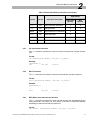
is used to specify the number of loops that will be carried out by the following
instructions. The counter is backed up with a 16 level stack. When the counter is loaded
with the LDC instruction the previous count is ‘pushed’ onto the stack. When the loop
that is actually using the counter has finished, the previous count is ‘popped’ off the
stack back onto the counter.
This instruction must be used with the following instructions: GONZ, CALLZ and CALLM.
Format:
LDC,n [INSTRUCTION TOKENS] <VEC_DEF> {<F_DATA>}
Schlumberger ITS 9000PX/MX Subroutine Memory Option User Manual - 740018904 / Rev 01
2-9
2
Subroutine Memory Programming
Example:
SUBROUTINE_F;
INC
LDC,3
LABEL1;
INC
INC
GONZ,
LABEL1
...
...
2.2.15
VEC_DEF
VEC_DEF
{001010}
{011010}
VEC_DEF
VEC_DEF
VEC_DEF
{001110}
{101010}
{101011}
LDCH (Load Loop Counter Conditional) Instruction
The LDCH instruction has the same function as the LDC instruction described above
except that the counter is not loaded if the LDCH instruction is found at the step following
a GONZ or RET instruction in a loop that has not finished.
Format:
LDCH,n [INSTRUCTION TOKENS] <VEC_DEF> {<F_DATA>}
Example:
SUBROUTINE_F;
INC
LDC,2
LABEL1;
INC
LABEL2;
LDCH,4
INC
INC
GONZ,
LABEL2
GONZ,
LABEL1
...
...
2.3
VEC_DEF
VEC_DEF
{001010}
{011010)
VEC_DEF
{111010)
VEC_DEF
VEC_DEF
VEC_DEF
VEC_DEF
VEC_DEF
{011010)
{001110)
{101111)
{101011)
{111011)
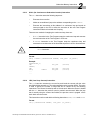
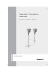
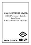
Parameter Passing
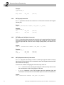
The F_Data for the Subroutine Memory can be sourced from either the Subroutine
Memory or the Main Memory. The selection of the source of the F_Data is made using
a Parameter Select directive. Up to a maximum of 256 Main/Sub Memory F_Data
source selection combinations can be used. Figure 2.1 shows an example of parameter
passing.
2-10
Schlumberger ITS 9000PX/MX Subroutine Memory Option User Manual - 740018904 / Rev 01
Parameter Passing
Param
Select
Combination
2
Tester Channel
0
Max
0
1
8
254
255
Param
Select
Address
F_Data
Source
Selection
Subroutine
Memory
F_Data
Main
Memory
Figure 2.1 F_Data Source Selection Block Diagram
The source of the F_Data for each PINDEF is identified in the test vector as follows:
•
A value written according to the PINDEF radix represents the F_Data for this
PINDEF in the Subroutine Memory.
•
An ‘=’ sign signifies the Main Memory is the source of the F_data for the PINDEF.
This F_Data is sourced from the relevant PINDEF position in the Main Memory
using a PARAM instruction token.
If the same F_Data is required to be sourced from the Main Memory regardless of the
parameter select combination used in the Subroutine Memory only a single PARAM
instruction token needs to be used in the Main Memory.
If the different F_Data is required to be sourced from the Main Memory regardless of
the parameter select combination used in the Subroutine Memory the same number of
PARAM instruction tokens need to be used in the Main Memory as the number of
different F_Data combinations required. To use this different F_Data the Main Memory
must be incremented to point to the correct PARAM instruction token. To do this a ‘+’
instruction token must be placed before the F_Data definition in the subroutine.
Schlumberger ITS 9000PX/MX Subroutine Memory Option User Manual - 740018904 / Rev 01
2-11
2
Subroutine Memory Programming
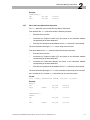
Example
The following example shows the parameter passing interaction between the Main and
Subroutine Memories.
Table 2.3 Main Memory
Line
Description
M1
MAIN_F
M2
INC
VEC_DEF
(001011)
Execute current line and
increment the Program
Counter.
M3
CALL, LABEL VEC_DEF
(101011)
Jump to LABEL1 in the
Subroutine (Line S2)
M4
PARAM
(101001)
Param vector
M5
PARAM
(111011)
Param vector
M6
HALT
VEC_DEF
(111011)
Table 2.4 Subroutine Memory
Line
2-12
Vector
Description
S1
SUBROUTINE_F
S2
LABEL1;
S3
INC,
VEC_DEF
(111011)
Execute current line and
increment Subroutine
address
S4
INC,
VEC_DEF
(1010=1)
Execute current line and
increment Subroutine
address. The = symbol
indicates the F-data is
sourced from the Main (Line
M4)
S5
INC,
+ VEC_DEF
(1=10=1)
Execute current line and
increment Subroutine
address. The = symbol
indicates the F_data is
sourced from the Main (Line
M4). The + symbol
increments the Main PC ( to
line M5)
Schlumberger ITS 9000PX/MX Subroutine Memory Option User Manual - 740018904 / Rev 01
Match Modes
2
Table 2.4 Subroutine Memory (Continued)
Line
2.4
Vector
Description
S6
INC,
+ VEC_DEF
(1110=1)
Execute current line and
increment Subroutine
address. The = symbol
indicates the F-data is
sourced from the Main (Line
M5). The + symbol
increments the Main PC ( to
line M6)
S7
HALT
VEC_DEF
(100011)
Executes current line and
returns to line M6
Match Modes
The Schlumberger ITS 9000PX/MX provides two types of Match Mode that are used to
ensure that t the DUT is in known state during the functional test. These three match
modes are:
❏
Fast
❏
Immediate
The match modes can either be executed with the RPTM instruction in the Subroutine
Memory or the Main Memory, or executed using the CALLM instruction from the Main
Memory to initiate a loop match sequence in the Subroutine Memory.
Regardless of the match mode or instruction (RPTM or CALLM) being used the match
SEQUENCE must be first defined. This sequence can contain up to 16 consecutive
PASS/ FAIL match conditions, e.g. SEQUENCE = PFP, meaning the match loop will
complete when a PASS-FAIL-PASS condition is found. Once the match SEQUENCE has
been defined it will be used for all match vectors within the same pattern.
2.4.1
Fast Match Mode
Using the fast match mode, once the match condition is found the pipeline must first be
emptied before executing the instruction following the RPTM or CALLM instruction. The
minimum length of the pipeline depends on the period value the match vector uses. The
pipeline length (Pipe) expressed in steps must be calculated as follows:
400ns
PIPE ≥ 15 + -------------------------------------------
Match Period
Eqn. 2.1
The fast match mode by default uses the same match sequence for ALL matching. If the
ONE_SHOT parameter is used, the predefined match SEQUENCE will be used for the first
match vector executed and all the following match vectors will only use the match
SEQUENCE = PASS.
Schlumberger ITS 9000PX/MX Subroutine Memory Option User Manual - 740018904 / Rev 01
2-13
2
Subroutine Memory Programming
2.4.2
Immediate Match Mode
The immediate match mode can only be used when the delay between the last edge of
match vector strobe and the end of the period is > 1.1 s. It is not therefore necessary
to calculate the pipeline length because the system has time to empty the pipeline
before executing the instruction following the RPTM.
The immediate match mode by default uses the same match sequence for ALL
matching. If the ONE_SHOT parameter is used, the predefined match SEQUENCE will be
used for the first match vector executed and all the following match vectors will only use
the match SEQUENCE = PASS.
2.4.3
Match Mode Programming
The match type must be defined before the SUBROUTINE_F or MAIN_F directives in the
pattern source code.
The syntax for the match mode is as follows:
MATCH {MODE = FAST ALL, SEQUENCE = “PFPF”, PIPE = 35}
Where the MODE can be:
MODE = FAST
ALL
Default
MODE = FAST
Default
MODE = FAST
ONE_SHOT
MODE = IMMEDIATE ALL
Default
MODE = IMMEDIATE
Default
MODE = IMMEDIATE ONE_SHOT
2-14
value
value is ALL
value
value is ALL
Schlumberger ITS 9000PX/MX Subroutine Memory Option User Manual - 740018904 / Rev 01
Documentation Feedback Form
We would appreciate you taking the time to complete this form and return it to us. Your answers will be a valuable
aid in improving the quality, and usefulness, of our documentation. All responses will be treated confidentially, and
remain the property of Schlumberger Technologies.
Publication
Schlumberger ITS9000PX/MX Subroutine Memory Option User Guide
Part Number:
740018904
Revision: 01
Date: July 4, 1994
How do you use this publication? ❏ As an introduction
❏ As a reference
❏ As a training text
❏ Other:
❏ Yes
❏
No
If a user guide, is it easy to understand? If a reference, is it easy to use? If not,
please explain why.
❏ Yes
❏
No
If a user guide, does it contain all the relevant information to understand and
operate the product? If not, what additional information would you like?
❏ Yes
❏
No
Were the illustrations helpful? If not, please explain why.
❏ Yes
❏
No
Would you like more illustrations? If so, of which subjects.
❏ Yes
❏
No
Is the information in the publication accurate? If not, please identify the
inaccuracies.
Other Comments
Name
Title
Date
Company
Division
Street
City
State
Zip or country
Return Address (U.S)
Return Address (Europe)
Phone
Technical Support Manager, Schlumberger Technologies,
1601 Technology Drive, San Jose, CA 95110.
Publications Manager, Schlumberger technologies,
34 rue Necker, 42028 Saint-Etienne, France.