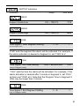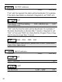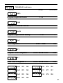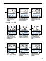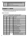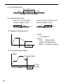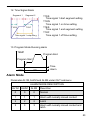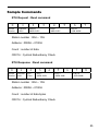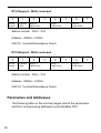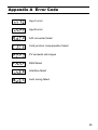
1
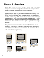
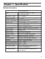
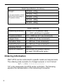
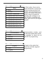
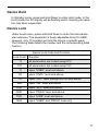
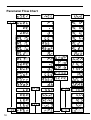
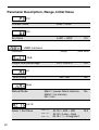
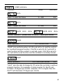
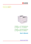
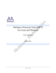
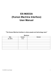
ANLY ELECTRONICS CO., LTD.
AT03 PID Temperature Controller
User’s Manual
AT - 403 / AT - 503 / AT - 603 / AT - 703 / AT - 903
www.anly.com.tw
2
Table of Content
Chapter 0
Overview
Chapter 1
Specification
Detail Specification
Detail Features
Ordering Information
Chapter 2
Installation
Mounting Procedure
Terminals
Chapter 3
Programming
Terminology
Power-up Sequence
Hierachal Tree Menu
Device Hold
Device Lock
Parameter Flow Chart
Parameter Description, Range, Initial Value
Examples
Chapter 4
Input
Chapter 5
Output
Chapter 6
Alarm
Alarm Type
Alarm Mode
Chapter 7
Communication
Sample Commands
Parameters and Addresses
Appendix A
Error Code
3
Chapter 0 : Overview
ANLY AT03 series is an 1 input, 2 output, 3 alarm, auto-tuning PID
temperature controller designed to accommodate comprehensive
needs in process automation and system integration.
Wide ranges of inputs are accepted, including thermocouple (T/C:
type K, J, T, R, E, S, B, N), Resistive Temperature Device (RTD:
Pt100, JPt100) and linear input (voltage, current). Up to 2 output
controls include relay, SSR, linear voltage, linear current and signal
retransmission. Servo motor control is also possible. Up to 3 alarms
are available and each has different functions and modes for customizations. This controller can have up to 8 segments for a single
process.
A separate optionsl channel allows Remote Set Point via linear
voltage or linear current. The same channel can also be used for
current transformer for heater break alarm. The users may chose
between RS-232 and RS-485 communication modules for links up
with computer for programming.
AT-903
AT-403
PV
PV
SV
SV
AT-703
PV
SV
SET
SET
AT - 403
AT - 903
SET
AT - 703
AT-503
PV
PV
AT-603
SV
SV
SET
SET
AT - 503
4
AT - 603
Chapter 1 : Specification
Detaile Information
Detail Specification
Type
AT - 403 / AT - 503 / AT - 603 /
AT - 703 / AT - 903
Operating voltage
100 ~ 240VAC
Rated Frequency
50 / 60 Hz
Power Consumption
Approximately 3.5VA
Sensor input
Thermocouple : K, J, T, R, E, S, B, N
RTD : Pt100, JPt100
Linear : Voltage, Current
Control output
Relay, Voltage, Linear, Motor Control
Alarm output
250VAC, 5A
Alarm fucntion
See Table on Page 49
Control method
PID, PI, P, On/OFF, Dead band
Setting
Digital setting with front keys
Communication
RS-232 or RS-485 (both optional)
Indicator
4-digit 7-segment-display
Ambient temperature
-10OC ~ +50OC
Storage temperature
-25OC ~ +65OC
Ambient humidity
34%~80% relative humidity with no
icing or condensation
Storage humidity
35%~95% relative humidity with no
condensation
5
Detail Specification (Continue)
Weight
(only approximation, actual
figures varie depending on
the options chosen)
AT-403: ~170g
AT-503: ~125g
AT-603: ~170g
AT-703: ~200g
AT-903: ~250g
Detail Features
Measuring accuracy
Within 0.3% of present value
or +-2OC, whichever is greater
Propotional Band
0.0 ~ 3000 sec (0.1 sec increment)
Integral Time
0 ~ 3600 sec (1 sec increment)
Derivative Time
0 ~ 900 sec (1 sec increment)
Control Period
0 ~ 150 sec (1 sec increment)
Sampling Period
300ms
Memory Protection
EEPROM non-volatile memory
(at least 100,000 write cycle)
Ordering Information
ANLY AT03 can be customized to specific needs and requirements.
The ordering code consists of a 10-digit numeral in 3-4-3 format :
AT- □ 0 3 - □□□□-□□□
“03” is the designation for AT03 series controllers. The following
explains the representation of the remaining 8 numerals.
6
AT- ■ 0 3 - □□□□-□□□
Dimension
4 = 96x48mm (1/8 DIN)
5 = 48x48mm (1/16 DIN)
6 = 48x96mm (1/8 DIN)
7 = 72x72mm
The dimension size is a measurement for the device face
plate. Note that AT-402 is vertical while AT-603 is horizontal,
although they have the same
DIN size.
9 = 96x96mm (1/4 DIN)
AT- □ 0 3 - ■□□□-□□□
1 is for both thermocouple and
Input
RTD sensor inputs. However,
1 = T/C or RTD
the sensor type also needs to
be specificied by users under
2 = 0~100mV
Level menu. 2 through 9 are for
3 = 0~20mA
linear inputs.
4 = 4~20mA
5 = 0~5V
6 = 0~10V
7 = 1~5V
8 = 2~10V
9 = 0~1V
7
AT- □ 0 3 - □■■□-□□□
Output 1
Output 2
(1 is standard)
0 = None
1 = Relay
1 = Relay
2 = Pulsed
2 = Pulsed
3 = 0~20mA
3 = 0~20mA
4 = 4~20mA
4 = 4~20mA
5 = 0~5V
5 = 0~5V
6 = 0~10V
6 = 0~10V
7 = 1~5V
7 = 1~5V
8 = 2~10V
8 = 2~10V
A relay output on Ouput 1 is
standard on all AT03. It can
be changed to any of the 9
types. Note that motor control
on Output 1 uses 3 terminals.
Therefore, Motor Control option
is not available with Output 2.
Therefore, “90” is the code for
motor controlo output.
9 = Motor Control
AT- □ 0 3 - □□□■-□□□
Alarm
1 = 1 alarm
2 = 2 alarms
3 = 3 alarms
8
1 alarm is standard on all AT03.
There can be upt o 3 alarms
on AT-403, AT-603, AT-703 and
AT-903. However, AT-503 can
only have up to 2 alarms.
AT- □ 0 3 - □□□□-■□□
Other
0 = None
1 = DC 24V
2 = Current Transformer
A = Remote Set Point 0~20mA
B = Remote Set Point 4~20mA
C = Remote Set Point 0~5V
In Other option, there can be
inputs for DC24V, current transformer and Remote Set Point
(R-SP). Current transformer is
used as the heater break alarm.
R-SP is used to change SV
remotely with volatage or current. AT-403 is availiable with
Other option but this will negate
Ouput2.
D = Remote Set Point 0~10V
E = Remote Set Point 1~5V
F = Remote Set Point 2~10V
AT- □ 0 3 - □□□□-□■□
Communication
0 = None
1 = RS=232
Communication module, such
as RS-232 and RS-485 module,
is availiable for direct link up
with PC for programming.
2 = RS-485
AT- □ 0 3 - □□□□-□□■
Program
0 = None
Program is the option that
gives the controller segment
programming.
1 = Program
9
Some models, due to their limited terminals, cannot be ordered with
all the features. Such limitations are:
AT-503 is not available with the Other and the 3
alarms options. Also, AT503 only uses two terminals
for its RS-485 communication while others use three
terminals
Servo motor control option occupies one Output 2
terminal. Hence, the Motor Control and Output 2 are
not available on the same device.
An example of order code is AT – 903 – 1111 – 000. It would have
1/4 DIN size, a sensor input, 2 relay outputs, 1 alarm, no Other
option, no Communication option and no Program Control options
Chapter 2 : Installation
d
A
C
D
c
B
E
b
a
Device Measurement
Panel Cutout Measurement
Type
A
B
C
D
E
a
b
c
d
AT-403
48
96
10.5
83
90
46+0.5
91+0.5
120
70
AT-503
48
48
10.5
83
45
46+0.5
46+0.5
70
70
AT-603
96
48
10.5
83
43
91
46
70
120
AT-703
72
72
10.5
83
67
68+0.5
68+0.5
100
100
AT-903
96
96
10.5
83
90
91
91
120
120
+0.5
+0.5
+0.5
+0.5
All measurements in millimeter (mm)
10
Mounting Procedure
1.
Make sure the front panel is no more than 10mm thick. Also,
each of the two brackets needs additional 6mm clearance
outside of the shell casing on each side.
2.
Make a panel cut-out precise to the measurement according to
the type. (see the table on the previous page)
3.
Insert the controller into the cutout from the front side of the panel
4.
Align the bracket so the notches are in their slots and the wide
side towards the front panel.
5.
Pinch the prongs and slide the bracket forward till the bracket
is firmly against the backside of the front panel.
6.
Repeat step 3 through 5 with another bracket on the other side.
Terminals
For wire terminations, the recommended terminals are fork or ring
terminals with #6 stud size, narrow tongue, and with insulation. Wire
gauge should be at least AWG 18.
3.7mm
Insulation Tube
^
6 .0mm
3.7mm
Insulation Tube
^
6 .0mm
11
Of all 5 types of ANLY AT03, there are 3 styles of terminal arrangements. AT-503 has 14 usable terminals; AT-403/603/903 have 19
usable terminals; AT-703 has 18 usable terminals. Each terminal
has numbering on the edge of the casing for easy identification.
The terminal layout for different models are as followed.
AT-403 / AT-603 / AT-903
5
-
6
16
NC
CLOSE
+
3
OPEN
NO
12
-
4
COM
13
+
5
-
6
14
CLOSE
15
20 T/R A+
+
24VDC
-
16
RS-485
8 AL2
T/R B- 8
SG 9
A
17
-
B
18
+
B
21 T/R B22 SG
10
11
-
23
12
+
24
AL3
AT-503
2
13
14
T/R A+ T/R B-
7
8
AL1
RS-485
1
COM
100~240 VAC
50/60 Hz
OUT2
Transmission
+
3
9
AL2
OUT1
12
NC
T/R A+ 7
19
RS-485
INPUT
B
18
7 AL1
9 COM
B
17
11
R-SP / CT
+
COM
10
2
AL3
4
15
1
AL2
-
OPEN
NO
-
AL1
3
+
24VDC
COM
14
100~240 VAC
OUT2
50/60 Hz
OUT1 Transmission
13
2
R-SP / CT
100~240 VAC
OUT2
OUT1 Transmission
50/60 Hz
1
+
A
AT-703
-
4
10
A
+
5
11
-
B
-
6
12
+
B
Chapter 3 : Programming
Terminology
AT-703
PV
SV
PRG
MAN
OUT1
AT
RP SK
OP2
1
2
10%
30%
40%
20%
OP1
3
50%
AL3
4
5
60%
70%
AL2
6
80%
7
AL1
90%
8
100%
PRG
SET
ANLY ELECTRONICS CO.
PV
Process value display
SV
Set value display
PRG
Programmable mode indicator
MAN
Manual mode indicator
Auto tuning indicator
AT
OP2
OP1
AL3
AL2
10%
1~8
~
100%
Control output 2, 1 indicator
AL1
OUT
Alarm output 3, 2, 1 indicator
Manipulated output display
Segment-in-process display
RP
Soaking mode indicator
SK
Ramping mode indicator
13
SET
Set Key
used to navigate within the hierachal set-up menu
Shift Key
used to shift in and out of the adjust mode
Down Key
used to decrease a value or to scroll down. When not in
programming mode, press-and-hold to call up lock or hold function.
Up Key
used to increase a value or to scroll up.
When not in programming mode, press-and-hold to go back
to the standby display.
Press-and-Release
press a key and release it immediately
Press-and-Hold
press a key and hold it untill the display has changed
Menu mode
a heirarchal tree menu with the PV display showing the menu title
and the SV display showing the submenu or the parameter.
Adjust mode
when the value at the SV diaply is flashing and ready to be adjusted
with the down or up button.
Standby mode
when the red PV display is sowing the temperature’s present value
and the SV display is showing the set value. At this mode, the
controller can ne changed to Menu mode or Operation mode.
Operation mode
when the device is running
14
Power-up Sequence
When the controller is powered up, it goes through 4 diagnostic stages.
1st stage: All displays light up. Users can verify that all
display LEDs are functional.
2nd stage: The PV display shows Input1 and the SV
display shows the temperature unit used, C. for Celsius
and F. for Fahrenheit. Following the unit is the sensor
type and range.
3rd stage: The displays show the range of temperature
according to the chosen sensor type and range. PV display
shows the minimum and the SV display shows the maximum
4th stage: The controller goes to the standby mode
and the device is operational.
Hierarchal Tree Menu
ANLY AT03 has a hierarchal tree menu to organize the parameters
and functions. There are 7 Submenus under Level.
When not in the adjust mode, press-and-hold Set or Up will always
bring the device to Standby mode.
User (uSEr) submenu
Control (CntL) submenu
Output (Out) submenu
15
Special Control (SPC) submenu
Input (inP) submenu
Program (ProG) submenu
Hide (HidE) submenu
16
Device Hold
In Standby mode, press-and-hold Down to enter Hold mode. In the
Hold mode, the SV display will be flashing HoLd, meaning all operation has been suspended.
Device Lock
Under Level menu, press-and-hold Down to enter the lock parameter submenu. The parameter is freely adjustable from 0 to 9999.
However, only 10 numbers will lock the device in specific ways.
The following table details the number and the corresponding table
function.
Device Lock Code And Function
Lock Code
Function
0
all parameters are locked except PV
101
all parameters are locked except SV
11
open “USER” level and above
22
open “CNTL” level and above
111
open “OUT” level (except OUTM) and above
222
open “INP” level and above
1100
open “SPC” level and above
2200
open “PROG” level and above
1122
open “HIDE” level and above
1234
open “USER” and “PROG” level only
17
Parameter Flow Chart
18
Same Group
Repeat same flow
as above group
19
Parameter Description, Range, Initial Value
PV
Process Value
LoSP ~ HiSP
SV
Set Value
LoSP ~ HiSP
0.0
USER submenu
(Parameter)
(Range)
(Initial Value)
OutL
Output level percentage
0.0 ~ 100.0%
0.0
No / Yes
No
At
Auto tuning
Man
Manual Mode
Man1 = power failure memory
Man2 = no memory
No = non
No
AL1S
Alarm 1 Set Value
AL1F = 1, 2
AL1F = 3, 4
AL1F = 10
20
AL1S = -200 ~ 200
AL1S = Losp ~ Hisp
AL1S = 1 ~ 8 segment
10.0
USER submenu
(Parameter)
(Range)
(Initial Value)
AL1L
Alarm 1 Lower Set Value
0 ~ 200
10.0
0 ~ 200
10.0
AL1u
Alarm 1 Upper Set Value
AL2S AL2L
AL2u
AL3S AL2L
AL2u
For AL2* and AL3* : please refer to the AL1* description above
SoAK
Soak Operation (only when AL1M= 8 or 9)
0.0 ~ 99.59 hr.min
0.00
“SoAK” only performs when AL1M is set at 8 or 9, and the controller is without program function. If AL1M is set at 8, AL1 will shift to
soak function and the contact is normally open; if AL1M is set at 9,
AL1 will shift to soak function and the contaact is normally closed.
rAmP
Ramp Operation
0.0 ~ 200.0 per minute
0.0
“rAmP” sets the rate of change for PV when the controller is without
program function. For example, if ramp is set at 10, the PV will
increase 10 degree per minute. However, if PV is higher than SV,
the PV will decrease 10 degree per minute.
21
USER submenu
(Parameter)
(Range)
(Initial Value)
PVoF
PV Offset
-200 ~ 200
0
If PV is not correct to SV, PV can be offset linearly with positive
or negative pvof .
PVrr
PV Ratio
0.001 ~ 9.999
If PV is not correct to SV, PV can be adjusted
with “pvrr”. The formula is:
PV (now) - PV (pre) * pvrr + pvof
1.000
PVrr > 1
0
PV
PVrr < 1
SVoF
SV Offset
-200 ~ 200
0.0
If SV is not correct to PV, SV can be offset linearly with positive or
negative “SVoF” .
Ct
Current Transformer Monitor
0.0 ~ 100.0 A
0.0
“Ct” is used to detect if the heater is broken. The value ranges from
0.0A ~ 100.0A. (“Ct” is only availiabe if the option is ordered)
22
USER submenu
(Parameter)
(Range)
(Initial Value)
HbA
Heater Break Alarm Value
0.1 ~ 100.0 A
0.1
“Hba” ranges from 0.1A ~ 100.0A. For example, when the control
output is on and “Ct” <= “Hba”, the heater is broken. The alarm
is triggered. Or when the control output is off and “Ct” >= “Hba”,
the alarm is then triggered. (“Hba” is only availiabe if the option is
ordered)
LbA
Loop Break Alarm Value
0.1 ~ 200.0 min
8.0
0.0 ~ 200.0
0.0
Lbd
LBA Dead Band
Parameters for Loop break Alarm. For example, when out1 = 0.0%
and “lba” has elapsed, PV should be below “lbd”. If PV is till within
“lbd”, the alarm is triggered. When out1 = 100% and “lba” time has
elapsed, PV should be higher than “lbd”. if PV is till within “lbd”, the
alarm is triggered. (“lba” and “lbd” is implemented through firmware
only)
rPtm
Repeat Times Monitor (only in Program function)
1 ~ 1000
“rptm” displays how many times the program has repeated thus far.
This parameter only works whenthe controller has program function
turned on.
23
CONTROL submenu
(Parameter)
(Range)
(Initial Value)
P1
Output 1 Propotional Band
0.0 ~ 3000
30.0
0 ~ 3600 sec
240
0 ~ 900 sec
60
0 ~ 150 sec
15
i1
Output 1 Integral Time
d1
Output 1 Derivative Time
Ct1
Output 1 Cycle Time
“ct1” is the cycle time for output 1. Normally, it is set at 0 for
4~20mA output, 1 for SSR output and 15 for relay output.
HSt1
Output 1 Hysteresis
0.0 ~ 200.0
0.0
-200 ~ 200
0.0
0.0 ~ 100.0 % (SV-P1*Ar)
100.0
AtoF
Auto Tuning Offset
Ar
Anti-Reset Windup
24
CONTROL submenu
(Parameter)
(Range)
(Initial Value)
“Ar” is for preventing over-shooting. This parameter sets an integral
delay. The setting ranges from 0 ~ 100%. At 100%, the integral will
perform when PV reaches the propotional band. At 50%, the integral will perform when PV reaches 50% of the propotional band.
P2
Output 2 Propotional Band
0.0 ~ 3000 sec
30.0
0.0 ~ 3600 sec
240
0.0 ~ 900 sec
60
0 ~ 150 sec
15
Output 2 Hysteresis
0.0 ~ 200.0
0.0
Dead Band / Overlap
-200.0 ~ 200.0
0.0
i2
Output 2 Integral Time
d2
Output 2 Derivative Time
Ct2
Output 2 Cyclic Time
HSt2
25
CONTROL submenu
(Parameter)
(Range)
100%
(Initial Value)
db
SV
0%
0
heating
cooling
SSV
Soft Start Set Value
0.0 ~ 200.0
120.0
“SSV” is used to prevent the heating system temperature rising
too quickly at the start. For example, to achieve 120 degree slowly,
“SSV” is set at 120.
Sout
Soft Start Output Percentage
0.0% ~ 100.0 %
30.0
“Sout” sets the output percentage when PV is under “SSV”.
Stme
Soft Start Fail Time
0 ~ 10 min
10
“Stme” sets the time interval when the soft start is deemed failed.
When the “Stme” time is reached and the PV has not reached
“SSV”, the soft start has failed and the controller will revert to SV.
26
CONTROL submenu
(Parameter)
(Range)
100%
100%
STME
0%
(Initial Value)
STME
SSV
0%
SV
SSV
SV
ruCy
Motor Valve Running Cycle
1 ~ 150sec
5
“ruCy” sets the running cycle time in motor valve control, the time
from close to open or from opento close.
Motor Valve
COM
Close
R
Close
Open
COM
Open
T
Out2
Out1
rPt
Program Repeat Time
1 ~ 1000
1
“rPt” set the number of times the program will repeat execution.
27
CONTROL submenu
(Parameter)
(Range)
(Initial Value)
StAt
Start Mode Selection
(only in Program function)
CoLd = Manual
rSET = start after power ON
Hot = start from memory after
power failure
CoLd
“StAt” sets the start mode the program. “CoLd” requires manual
start. “rSET” starts the program automatically after the power is
turned on. “Hot” starts from memory after a power failure.
PVSt
Start Point Selection (only in Program mode)
rSEt = start from 0
PV = start from PV
rSEt
wAit
Wait Value in Program
0.0 ~ 200.0
0.0
“wAit” sets the time the SV will wait for PV if PV chanes slower than
SV.
Pid
PID / Level PID Selection
Pid = PID
LPid = Level PID
Pid
“Pid” selects between PID (Pid) and Level PID (LPid). Level PID
allows upto 4 level of different PID.
28
CONTROL submenu
(Parameter)
(Range)
(Initial Value)
EndP
End of Program Control
Cont = Continuous
StoP = 1 program only
StoP
“EndP” controls the the flow of the program to be continuous (Cont)
or 1-program-only-and-stop (StoP).
OUTPUT submenu
(Parameter)
(Range)
(Initial Value)
AL1F
Alarm 1 Action Function
0 ~ 13
1
Please refer to Chapter 6 : Alarm for functio descriptions
AL1H
Alarm 1 Hysteresis
Out
0.0 ~ 200.0
0.0
AL1t
Alarm 1 in Program Mode on Time
0.00 ~ 99.59 hr.min
0.00
AL1M
Alarm 1 Special Mode Selection
1 ~ 11
0
Please refer to Chapter 6 : Alarm for mode descriptions
29
OUTPUT submenu
(Parameter)
(Range)
AL2F AL2H AL2t
AL1M
AL3F AL3H AL3t
AL3M
(Initial Value)
For AL2 and AL3, please refer to Al1 description above.
Act
Control Action Selection
CooL / HEAt
HEAt
Outm
Output Mode Selection (Please contact distributor for changes)
Please refer to Chapter 5 : Output for mode descriptions
O1LS
Output 1 Scale Low
0.0 ~ 100.0 %
17.6
0.0 ~ 100.0 %
96.0
O1HS
Output 1 Scale High
AO
Analog Output Selection
30
PV = transmit PV
SV = transmit SV
dEV = transmit (PV-SV)
MV = transmit output percentage
PV
OUTPUT submenu
(Parameter)
(Range)
(Initial Value)
O2LS
Output 2 Scale Low
0.0 ~ 100.0 %
17.6
0.0 ~ 100.0 %
96.0
O2HS
Output 2 Scale High
t1SS
Time Signal 1 Start Segment Setting
(only in Program mode)
1~8
1
“t1SS” sets the segment the alarm will be activated. For example, if
the alarm activation is desired in Segment 2, set “t1SS” at 2.
t1On
Time Signal 1 On Time Setting
(only in Program mode)
0.00 ~ 99.59 hr.min
0.01
“t1On” sets the time the alarm will be activated. For example, if the
alarm activation is desired after 3 minute in Segment 2, set “t1On”
at 3min and “t1SS” at 2. Note that the Program Time in Segment 2
(tP2) may be longer than 3 minute.
t1ES
Time Signal 1 End Segment Setting
(only in Program mode)
1~8
1
31
OUTPUT submenu
(Parameter)
(Range)
(Initial Value)
“t1es” sets the segment the alarm will be deactivaed. For example,
if the alarm deactivation is dersired in Segment 6, set “t1ES” at 6.
t1oF
Time Signal 1 Off Time Setting
(only in Program mode)
0.00 ~ 99.59 hr.min
0.01
“t1oF” sets the time the alarm will be deactivaed. For example, if
the alarm deactivation is desired after 7 minute in Segment 6, set
“t1oF” at 7min and “t1ES” at 6. Note that the Program Time in Segment 6 may be longer than 7 minute.
t2SS
t2On
t2ES
t2oF
For t2 parameters descriptions, please refer to see t1 parameters
(t1SS, t1On, t2ES, t2oF).
INPUT submenu
(Parameter)
(Range)
(Initial Value)
inP1
Input 1 Selection
K2
LoSP
Low Set Point
32
LoSP ~ HiSP
0.0
INPUT submenu
(Parameter)
(Range)
(Initial Value)
HiSP
High Set Point
LoSP ~ HiSP
400.0
-1999 ~ 9999
0.0
-1999 ~ 9999
100.0
LoAn
Analog Input Range Low
HiAn
Analog Input High
A1LS
Analog Inpput 1 Scal Low
0 ~ FFFF
A1HS
Analog Input 1 Scale High
0 ~ FFFF
unit
Unit Selection
C / OF / non
O
C
O
dP
Decimal Point
0 / 0.0 / 0.00 / 0.000
0.0
33
INPUT submenu
(Parameter)
(Range)
(Initial Value)
FiLt
Digital Filter
0.001 ~ 1.000
0.900
inP2
Input 2 Selection
non = no function
Ct = current transformer
rmSV = remote SV
non
A2LS
Analog Input 2 Scale Low
0 ~ FFFF
A2HS
Analog Input 2 Scale High
0 ~ FFFF
SPECIAL CONTROL submenu
(Parameter)
(Range)
(Initial Value)
bAud
Baud Rate
2.4K / 4.8K / 9.6K / 19.2K / 38.4K
9.6K
Addr
Address
34
0 ~ 31
0
SPECIAL CONTROL submenu
(Parameter)
(Range)
(Initial Value)
LEV1
Leve 1 PID Range
LoSP ~ HiSP
400
LoSP ~ HiSP
400
LoSP ~ HiSP
400
1~4
1
LEV2
Level 2 PID Range
LEV3
Level 3 PID Range
LVSL
Level PID Selection Monitor
Level PID Selection Monitor selects whiche level of PID to be
monitored. For example, if Level3 parameters (L3P1, L3P1, L3d1...
etc.) are to be monitored, set “LVSL” to 3. Note that PID parameter
under CONTROL submenu needs to set at Level PID (LPiD).
L1P1
Level 1 Propotional Band for Output 1
0.0 ~ 3000
30.0
0 ~ 3600 sec
240
L1i1
Level 1 Integral Time for Output 1
35
SPECIAL CONTROL submenu
(Parameter)
(Range)
(Initial Value)
L1d1
Level 1 Derivative Time for Output 1
0 ~ 900 sec
60
0.0 ~ 100.0 %
100.0
0.0 ~ 3000 sec
30.0
0 ~ 3600 sec
240
0 ~ 900
60
L1Ar
Level 1 Anti-Reset Windup
L1P2
Level 1 Propotional Band for Output 2
L1i2
Level 1 Integral Time for Output 2
L1d2
Level 1 Derivative Time for Output 2
L2P1
L2i1
L2d1
L2Ar
L2P2
L2i2
L2d2
L3P1
L3i1
L3d1
L3Ar
L3P2
L3i2
L3d2
L4P1
L4i1
L4d1
L4Ar
L4P2
L4i2
L4d2
For Level2, Level3 and Leve4 parameters description, please refer
to Level1 parameters (L1P1, L1i1, L1Ar, L1P2, L1i2, L1d2).
36
PROGRAM submenu
(Parameter)
(Range)
(Initial Value)
SEG
Program Segment Monitor
1~8
tiME
Program Countdown Monitor
EndS
Program Segment End Setting
1~8
1
SV1
SV in Segment 1
LoSP ~ HiSP
100
0.00 ~ 99.59 hr.min
0.00
0.00 ~ 99.59 hr.min
0.00
tP1
Program Time in Segment 1
tS1
Soak Time in Segment 1
SV2
tP2
tS2
SV6
tP6
tS6
SV3
tP3
tS3
SV7
tP7
tS7
SV4
tP4
tS4
SV8
tP8
tS8
SV5
tP5
tS5
37
PROGRAM submenu
(Parameter)
(Range)
(Initial Value)
For Segment2 to Segment8 parameters description, please refer
to Segment1 parameters (SV1, tP1, tS1).
SV2
SV3
EndS = 5
SV4
SV1
SV5
tS1
tP1
tS2
tP2
tS3
tP3
tS4
tP4
tS5
tP5
PROGRAM submenu
(Parameter)
(Range)
~
Parameters under USER Submenu
~
Parameters under CONTROL Submenu
~
Parameters under OUTPUT Submenu
38
(Initial Value)
A. Example : How to set “SV” at 200OC
Press-and-hold
till
SV blinks. Press
again to move the digit
Press
to increase or
press
to decreasae
the value
Press
value
to set the SV
B. Example : How to set AL1S at 20OC
Press-and-hold
till
PV shows “AL1S”
Press
setting
Press-and-hold
till
SV blinks, press
again to move the digit
to enter AL1
Press-and-hold
return to PV/SV
windows
Press
to increase or
press
to decrease
the value
to
39
C. Example : How to set “AT” (auto tuning)
Press
to show “AT”
on PV windows
Press
setting
Press
to show
“no” flickering on SV
windows
to enter AT
Press
to show “yes”
on SV window
Press-and-hold
to
return to PV/SV window
D. Example : How to enter different “level” for setting parameter
(1) Enter “CntL” level
Press-and-hold
till
“LEVL” on PV window
(under PV/SV initial
window)
40
Press
to show
“user” flickering on
SV window (under PV
show “LEVL”
Press
to show
“cnt1” on SV window
then press
to enter
this level
Press-and-hold
to
show “P1” on PV
window
Press-and-hold
to
continue other parameters in this level
Press-and-hold
to
return to PV/SV initial
window
Press-and-hold
to
show “LEVL” on PV
window (under PV/SV
initial window)
Press
to show “user”
flikering on SV window
(under PV show “LEVL”
Press
to show “out”
on SV window then
press
to enter this
level
Press
to show
“AL1F” on PV window
Press-and-hold
to
continue other parameters
in this level
Press-and-hold
to
return PV/SV initial
window
(2) Enter “Out” level
41
(3) Enter “inP” level
Press-and-hold
to
show “LEVL” on PV
window (under PV/SV
initial windows)
Press
to show “user”
flickering on SV window
(under PV “LEVL”)
Press
to show “inP”
on SV window then
press
to enter this
level
Press-and-hold
to
continue other parameters
in this level
Press-and-hold
to
return PV/SV initial
window
Press
to show “user”
flickering on SV window
(under PV show “LEVL”)
Press
to show “SPC”
on SV window then
press
to enter this
level
l
Press-and-hold
to
show “inP1” on PV
window
(4) Enter “Spc” level
Press-and-hold
to
show “LEVL” on PV
window (under PV/SV
initial window)
42
Press-and-hold
show “baud” PV
window
to
Press-and-hold
to
continue other parameters
in this level
Press-and-hold
to
return to PV/SV initial
window
(5) Enter program level
* “OUTM” in “out” level must be selected at “8” or “9”
Press-and-hold
to
show “LEVL” on PV
window (under PV/SV
initial window)
Press
to show “user”
flickering on SV window
(under PV show “LEVL”)
Press
to show “PROG”
on SV wndow then press
to enter “PROG” level
Press-and-hold
to
show “SEG” on PV
window, this parameter
only display executing
segment
Press-and-hold
to
continue other parameters, this parameter
only display time for
ramp or soak steps
Press-and-hold
to
return to PV/SV initial
window
43
Press
ro show SV
flickering, the press
key to set ending
segment
Press
to set SV for
segment 1
Press
to set time for
ramp of segment 1
The operation from SV2 to SV
are the same as SV1
8
Press
to set time for
soak of segment 1
(6) Enter “Hide” level
In this level, the user can arrange parameter order or hiding from No. 1-2 to 1-22, 2-14 to
2-17 and 3-20 to 3-27 (please refer to level parameter flow chart), but same parameter
can not be arranged in 2 positions at the same time. For example, to arrange “OUTL” to
1-3 you need to cancel it in 1-2 first. When canceling or to hide, select “non” on the “SV”
Press-and-hold
to
show “LEVL” on PV
window (under PC/SV
initial window)
44
Press
to show “user”
flickering on SV window
(under PV show “LEVL”)
Press
to show “Hide”
on SV window then press
to enter this level
Press-and-hold
to
show “1-2” on PV window
Press-and-hold
to
continue other parameters
at this level
Press-and-hold
to
return to PV/SV initial
window
Press-and-hold
to
show “OUTL” flickering
then press
to “non”
for hiding and cancelling
or press
to select
other parameters
If “non” is selected in1-2 and
is pressed, 1-2 will not
display anything. If other parameter is selected in 1-2, it
will display that parameter.
The operation in 1-2 to 1-22, 2-14 to 2-17 and 3-20 to
3-27 are all the same.
E. Example : How to set “LOCK” function
Press-and-hold
to
show “LEVL” on PV
window (under PV/SV
initial window)
Press-and-hold
to
show “LOCK” on PV
window
Press
till SV blinks
45
Press
to increase or
press
to decrease
code number
46
Press
setting
to enter “LOCK”
Press-and-hold
to
return to PV/SV initial
window
Chapter 4 : Input
AT03 series is designed to accept thermocouples sensor, RTD
sensors, linear voltage and linear current inputs. The input type is
specified partly through hardware and needs to be specified at the
time of ordering.
For sensor inputs (thermocouple and RTD), AT03 can accept K, J,
T, R, E, S, B, N or N type thermocouple and Pt100 or JPt100 RTD
sensors. There are different segments in firmware to optimize the
sensing performance. The specific segment is specified through
firmware and is specified through the parameter inP1 under inp
submenu.
For linear input, all vairotions are soecified through hardware at the
time of ordering.
Input Hardware ordering information
AT- □ 0 3 - ■□□□-□□□
Input
1 = T/C or RTD Sensor
2 = 0~100mV
3 = 0~20mA
4 = 4~20mA
5 = 0~5V
6 = 0~10V
7 = 1~5V
8 = 2~10V
9 = 0~1V
47
Parameter INP1 under INP submenu
Type
INP1
K
K1
0 ~ 200
32 ~ 392
K2
0 ~ 400
32 ~ 752
K3
0 ~ 800
32 ~ 1472
K4
0 ~ 1000
32 ~ 1832
K5
0 ~ 1200
32 ~ 2192
J1
0 ~ 200
32 ~ 392
J2
0 ~ 400
32 ~ 752
J3
0 ~ 800
32 ~ 1472
J4
0 ~ 1000
32 ~ 1832
J
J5
T
F
O
0 ~ 1200
32 ~ 2192
T1
-50 ~ 50
-58 ~ 122
T2
-100 ~ 100
-148 ~ 212
T3
-200 ~ 400
-328 ~ 752
R
R
0 ~ 1700
32 ~ 3092
E
E
0 ~ 1000
32 ~ 1832
S
S
0 ~ 1700
32 ~ 3092
B
B
0 ~ 1800
32 ~ 3272
N
N
-200 ~ 1300
-328 ~ 2372
Pt
Pt1
-50 ~ 50
-58 ~ 122
Linear
48
C
O
Pt2
0 ~ 100
32 ~ 212
Pt3
0 ~ 200
32 ~ 392
Pt4
0 ~ 400
32 ~ 752
Pt5
-200 ~ 600
-328 ~ 1112
jPt
-200 ~ 500
-328 ~ 932
Lin
-1999 ~ 9999
Chapter 5 : Output
AT03 series has highly customizable outputs for customers’ specific
needs. It may have upto 2 control outputs. The desired ouputs
needs to be specified at the time of ordereing and set by the users
under OUTPUT submenu according to the hardware.
Output hardware ordering information
AT- □ 0 3 - □■■□-□□□
Output 1
Output 2
(1 is standard)
0 = None
1 = Relay
1 = Relay
2 = Pulsed
2 = Pulsed
3 = 0~20mA
3 = 0~20mA
4 = 4~20mA
4 = 4~20mA
5 = 0~5V
5 = 0~5V
6 = 0~10V
6 = 0~10V
7 = 1~5V
7 = 1~5V
8 = 2~10V
8 = 2~10V
9 = Motor Control
Parameter OUTM under OUT submenu
OUTM
Mode
1
Single Output
2
Dual Output
3
Motor Control, A contact
4
Motor Control, B contact
5
Single output with transmitter
6
Single output with soft start
49
7
Single output with transmitter and soft start
8
Program control
9
Program control with trsnamitter
Chapter 6 : Alarm
AT03 models can have upto 3 alarms. Each alarm can be programmed
to different function and different mode.
Alarm Function
Parameter AL1F, AL2F and AL3F under OUT submenu
ALARM FUNCTION DESCRIPTION
50
AL1F
AL2F
AL3F
Description
0
0
0
No Alarm
1
1
1
Deviation High Alarm
2
2
2
Deviation Low Alarm
3
3
3
Absolute High Alarm
4
4
4
Absolute Low Alarm
5
5
5
Deviation high/low Alarm
6
6
6
Band Alarm
7
7
7
System Failure Alarm
8
8
8
Loop break alarm
9
9
9
Heater Break Alarm
10
10
10
Segment Ending Alarm
11
Program Ending Alarm
11
11
12
12
13
13
Not
Availiable
Time Signal Alarm
Program Mode Running alarm
1. Deviation High Alarm
SV+AL1S
OFF
ON
SV
2. Deviation Low Alarm
PV
SV+AL1S
OFF
ON
SV
PV
3. Absolute High Alarm
OFF
ON
AL1S
PV
4. Absolute Low Alarm
OFF
ON
AL1S
5. Deviation High/Low Alarm
SV-AL1L
ON
OFF
SV+AL1U
ON
SV
PV
PV
6. Band Alarm
SV+AL1U
SV-AL1L
OFF
ON
SV
OFF
PV
7. System Failure Alarm
Alarm is triggered when the system has failed.
51
8. Loop break alarm
ON
Non-alarm area
OFF
ON
PV-LBD PV PV+LBD
9. Heater Break Alarm
Low or no current flow
Control output is ON
OFF
ON
C.T.
Over current or short circuit
Control output is OFF
OFF
ON
C.T.
10. Segment Ending Alarm
OFF
AL1T
ON
AL1S
1~8 segment
AL1T
0.00 Flicker alarm
(other) ON delay time
99.59 Continuous alarm
11. Program Ending Alarm
TEMP
Program End
•
•
OFF
52
ON
Time
Alarm
12. Time Signal Alarm
Segment 1
Segment 2
T1ON
T1OF
Time signal 1 outputtin g
T1SS
Time signal 1 start segment setting
T1ON
Time signal 1 on time setting
T1ES
Time signal 1 end segment setting
T1OF
Time signal 1 off time setting
13. Program Mode Running alarm
TEMP
Program End
•
Program Start
•
OFF
Time
Alarm
ON
Alarm Mode
Parameter AL1M, AL2M and AL3M under OUT submenu
ALARM MODE DESCRIPTION
AL1M
AL2M
AL3M
0
0
0
Descrition
Normal
1
1
1
Alarm with nomally closed contact
2
2
2
Latch
3
3
3
Alarm with nomally closed contact and
latch
53
ALARM MODE DESCRIPTION (continue)
4
4
4
Alarm with inhibit
5
5
5
Alarm with inhibit and normally closed
contact
6
6
6
Alarm with inhibit and latch
7
7
7
Alarm with inhibit, normally closed
contact and latch
8
9
10
11
(Mode 8, 9,
10, 11 are not
availiable on
Alarm2 and
Alarm3. Only
Alarm1 has all
11 modes)
Alarm with on-delay timer
Alarm with on-delay timer but normally
closed contact
Alarm with soaking timer
Alarm with soaking timer but normally
cloased contact
Chapter 7 : Communication
AT03 has optional RS-232 and RS-485 module, which enables
the controller to be programmed and monitored remotely.
Interface
RS-232, RS-485
Baud Rate
2400 bps, 4800 bps, 9600 bps, 19200bps, 38400 bps
Data Format ModBus protocol RTU mode
Data Frame
0
B0
1 start bit
54
B1
B2
B3
8 data bits
B4
B5
B6
B7
1
1 stop bit
Sample Commands
RTU Request : Read command
0
Station
Number
1
Function
0X03
2
3
4
Address
(MSB~LSB)
5
6
Count
(MSB~LSB)
7
CRC16
(LSB~MSB)
Station number : 00H ~ 1FH
Adderss : 0000H ~ 0100H
Count : number of data
CRC16 : Cyclical Redundancy Check
RTU Response : Read command
0
1
Station
Number
Function
0x03
2
Byte
Count
3
Data 1
(MSB~LSB)
4
5
Data 2
(MSB~LSB)
6
7
8
CRC16
(LSB~MSB)
Station number : 00H ~ 1FH
Adderss : 0000H ~ 0100H
Count : number of data bytes
CRC16 : Cyclical Redundancy Check
55
RTU Request : Write command
0
Station
Number
1
Function
0X06
2
3
Address
(MSB~LSB)
4
5
Count
(MSB~LSB)
6
7
CRC16
(LSB~MSB)
Station number : 00H ~ 1FH
Adderss : 0000H ~ 0100H
CRC16 : Cyclical Redundancy Check
RTU Request : Write command
0
Station
Number
1
Function
0X06
2
3
Address
(MSB~LSB)
4
Count
(MSB~LSB)
5
6
7
CRC16
(LSB~MSB)
Station number : 00H ~ 1FH
Adderss : 0000H ~ 0100H
CRC16 : Cyclical Redundancy Check
Parameters and Addresses
The following table on the next two pages lists all the parameters
and their corresponding addresses under ModBus RTU.
56
PARAMETERS AND ADDRESSES
LEvL
00
rPtm
18
AL1F
30
t2On
LoCK
01
P1
19
AL1H
31
t2ES
48
49
Sv
02
i1
1A
Al1t
32
t2oF
4A
OutL
03
d1
1B
AL1m
33
inP1
4B
At
04
Ct1
1C
AL2F
34
LoSP
4C
mAn
05
HSt1
1D
AL2H
35
HiSP
4D
AL1S
06
AotF
1E
AL2t
36
LoAn
4E
AL1L
07
Ar
1F
AL2m
37
HiAn
4F
AL1U
08
P2
20
AL3F
38
A1LS
50
AL2S
09
i2
21
AL3H
39
A1HS
51
AL2L
0A
d2
22
AL3t
3A
unit
52
AL2U
0B
Ct2
23
AL3m
3B
dp
53
AL3S
0C
HSt2
24
Act
3C
FiLt
54
AL3L
0D
db
25
Outm
3D
inP2
55
AL3U
0E
SSv
26
O1LS
3E
A2LS
56
SOAK
0F
Sout
27
O1HS
3F
A2HS
57
rAmP
10
Stme
28
AO
40
PvoF
11
rUCy
29
O2LS
41
bAud
59
Pvrr
12
rPtm
2A
O2HS
42
Addr
5A
SvoF
13
StAt
2B
t1SS
43
LEv1
5B
Ct
14
PvSt
2C
t1On
44
LEv2
5C
HbA
15
wAit
2D
t1ES
45
Lev3
5D
LbA
16
Pid
2E
t1oF
46
LvSL
5E
Lbd
17
EndP
2F
t2SS
47
L1P1
5F
57
Appendix A Error Code
Input1 error
Input2 error
A/D converter failed
Cold junction compensation failed
PV exceeds set ranges
RAM failed
Interface failed
Auto tuning failed
59
Note :
60
Note :
61
Note :
62
Note :
63
ANLY Electronics Co., Ltd.
N0. 19, Lane 202, Fushou St.,
Shinjuang City, Taipei, Taiwan 242
Phone : 886-2-2996-3202
Fax : 886-2-2996-2017
Content are aubject to change without notice
Printed in Taiwan
01A-MK9403