1
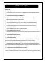
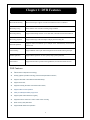
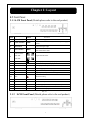
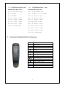
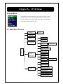
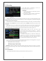
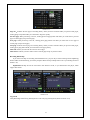
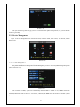
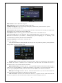
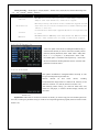
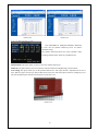
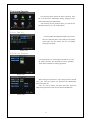
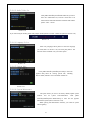
0
CONTENTS
2.1 Front Panel........................................................................................................................................................ 1
2.1.1 4-CH Front Panel (Details please refer to the real product)................................................................... 1
2.1.2 8-CH Front Panel (Details please refer to the real product)................................................................ 1
2.2 Rear Panel ......................................................................................................................................................... 2
2.2.1 4-CH Rear Panel (Details please refer to the real product) ................................................................. 2
2.2.2 8-CH Rear Panel (Details please refer to the real product) ................................................................. 2
2.3
3.1
3.2
3.3
Remote Controller(Only for reference)........................................................................................................... 3
Hard Disk Installation ..................................................................................................................................... 5
Camera and Monitor Connection.................................................................................................................... 5
Power Supply connection ............................................................................................................................... 5
Chapter 4: DVR Boot up.................................. 6
4.1 System Initialization ......................................................................................................................................... 6
4.2 Main Interface................................................................................................................................................... 6
Pop-up Menu........................................................................................................................................................... 7
5.1 Main Menu Preview.......................................................................................................................................... 7
5.2 Main Menu........................................................................................................................................................ 8
5.2.1 Camera ................................................................................................................................................... 8
5.2.2 Recording............................................................................................................................................... 9
5.2.3 Network Set ........................................................................................................................................... 9
5.2.4 Recording Search ................................................................................................................................. 11
5.2.5 Device Management ............................................................................................................................ 13
5.2.6 System Function................................................................................................................................... 17
5.3 Menu Locking.............................................................................................................................................. 19
5.4 Recording Search............................................................................................................................................ 19
5.5 PTZ Control .................................................................................................................................................... 19
5.6 Manual Recording........................................................................................................................................... 19
5.7 Stop recording................................................................................................................................................. 19
Chapter 6: NetViewer Program .......................... 20
6.1 Widget download and installation................................................................................................................... 20
6.2 Log-in Net-viewer........................................................................................................................................... 20
6.3 Main Interface of Net-viewer.......................................................................................................................... 20
6.3.1 Menu column ....................................................................................................................................... 21
6.3.2 PTZ Control ......................................................................................................................................... 24
6.3.3 Live play Control ................................................................................................................................. 25
Chapter 7:Specification............................... 25
8.1 Troubleshooting .............................................................................................................................................. 26
8.2 Usage Maintenance......................................................................................................................................... 27
8.3 System connection Configuration................................................................................................................... 27
8.4 Accessory (Optional) ...................................................................................................................................... 28
1
Safety Instruction
General safety
1.
Use proper power source.
Do not operate this product from a power source that applies more than specified voltage (100-240V
AC).
2.
Never insert anything metallic into the DVR case.
Putting something into the DVR case can be a source of dangerous electronic shock.
3.
Do not operate in wet & dusty or use near water.
Avoid places like a damp basement or dusty hallway.
4.
Do not expose this product to rain or use near water.
If this product accidentally gets wet, unplug it and contact an authorized dealer immediately.
5.
Keep product surfaces clean and dry.
To clean the outside case of the DVR, use lightly dampened cloth with water (no solvents).
6.
Provide proper ventilation.
This DVR has a built in fan that properly ventilates the system.
7.
Do not attempt to remove the top cover.
If there are any unusual sounds or smells coming from the DVR, unplug it immediately and contact an
authorized dealer or service center.
8.
Do not attempt to remove the top cover.
Warning: You may be subjected to severe electrical shock if you remove the cover of the DVR.
9.
Handle DVR box carefully.
If you accidentally drop your DVR on any hard surface, it may cause a malfunction. If the DVR doesn’t
work properly due to physical damage, contact an authorized dealer for repair or exchange.
10. Use standard lithium cell battery. (NOTE: Manufacturer has preinstalled battery.)
The standard lithium cell 3v battery located on the mother board should be replaced if the time clock
does not hold its time after the power is turned off. Warning: unplug the DVR before replacing battery or you
may be subjected to severe electrical. Properly dispose of old batteries.
11. Install this product under good air circulation conditions.
This DVR system contains a hard disk drive inside, which generates much heat during operation.
Therefore, do not block air holes (bottom, upper, sides and back) of the DVR that cool down the system
while running. Install or place this product in an area where there is good air circulation.
2
Chapter 1: DVR Features
Real time monitoring
With virtual output, Support real time surveillance function via Monitor
Recording saving
Allow DVR to save real-time recording image to HDD
Recording backup
Support DVR backup function via U flash disk, removable disk and hard disk etc.
Recording playback
Support DVR single CH and multiple CH playback recording file
Network operation
Supports remote surveillance up to multiple users simultaneously with licensed
software AP
Alarm Setting
Support HDD & video input alarm management and external alarm signal input
Mouse Operation
Support Mouse operation to more quickly setup system parameter.
PTZ Control
Supports PTZ camera operations through RS-485, and PTZ Hot Point function
List 1-1
DVR Features:
l
ÏH.264 Video Compression Technology;
l
Friendly graphics operation technology and semi-transparent Menu interface;
l
Support U flash disk / removable disk and HDD backup;
l
Support 3G function;
l
Supports recording list search and advanced time search;
l
Support outline of menu operation
l
Allow you instantly leave/lock pop-up menu.
l
Support system self-maintenance regularly
l
Supports manual / continuous / motion / alarm / timer recording
l
Quick recovery fault parameters
l
Support flexible USB mouse operation
0
Chapter 2: Layout
2.1 Front Panel
2.1.1 4-CH Front Panel (Details please refer to the real product)
Item
Key title/Indicator
1
Power Switch
2
Power indicator
3
IR Receiver
4
HDD indicator
5
Channel Select:
CH1 CH2
CH3 CH4
Single Channel Select
6
QUAD
Quad display On Live display or playback mode
7
REW
7
Left direction key / Rewind play
8
PAUSE
;
Pause / play frame by frame
9
PLAY
4
Enter into pop-up Menu/Play
10
FWD
8
Right direction key / Forward play
11
STOP
<
Stop Playback; stop manual recording
12
REC
13
MENU/ESC
3
Enter into main menu or exit menu
14
Up
5
Up direction key
15
SEL/EDIT
4
Enter into pop up menu; Select key / Edit key
16
Down
6
Down direction key
17
PTZ:
Marks
Functions
On/off Power supply
PWR
If the “Green” indicator is on, that means power supply is
normal
Receive IR signal input
HDD
If the “Red” indicator flash, that means HDD of DVR is
under read/written status.
Manual recording
The button allows you proceed PTZ control
List 2-1
2.1.2
8-CH Front Panel (Details please refer to the real product)
1
1
Power Switch
11
PLAY: Play / Zoom in(out)
2
PWR:PWR Indicator
12
FWD: Forward / Iris
3
HDD: HDD Indicator
13
STOP: Stop key
4
SEARCH: Recording Search 14
REC: Manual Recording
5
MUTE: Mute key
15
MENU/ESC/LEFT: Menu / ESC / Left key
6
CH- :Switch to previous CH
16
UP: Up key
7
CH+ :Switch to next CH
17
SEL/EDIT/RIGHT: Select / Edit / Right key
8
ALL: Preview all CH
18
DOWM: Down Key
9
REW: Rewind / Focus
19
PTZ: Enter / Exit PTZ control
10
PAUSE: Pause/Dwell time key
2.2 Rear Panel
2.2.1
4-CH Rear Panel (Details please refer to the real product)
1
CH1-4: Video input
6
VGA port (Optional)
2
Video Output
7
USB port
3
Audio Input
8
Mouse port
4
Audio Output
9
RS-485/Sensor/Alarm port
5
LAN: LAN port
10
Power switch port
2.2.2
8-CH Rear Panel (Details please refer to the real product)
1
CH1-8: Video input
6
Audio Output
2
Video Output
7
USB port
3
Audio Input
8
Mouse port
4
LAN: LAN port
9
RS-485/Sensor/Alarm port
5
VGA port (Optional)
10
Power switch port
2
4-CH: RS485/Sensor/Alarm ports
8-CH: RS485/Sensor/Alarm ports
definition(from right to left):
definition(from right to left):
Pin 1-2:PTZ Control port
Pin 1-2:PTZ Control port
Pin 1:RS-485A
Pin 1:RS-485A / Pin 2:RS-485B
Pin 2:RS-485B
Pin 3-4: Sensor 1 input
Pin 3-4: Sensor 1 input
Pin 4-5: Sensor 2 input
Pin 5-6: Sensor 2 input
Pin 6-7:
Pin 7-8:
Pin 7-8:Sensor 4 input
Sensor 3 input
Sensor 3 input
Pin 9-10:Sensor 4 input
Pin 9-10: Sensor 5 input
Pin 11-12:Alarm Output
Pin 10-11: Sensor 6 input
Pin 12-13: Sensor 7 input
Pin 13-14: Sensor 8 input
Pin 15-16:Alarm Output
2.3 Remote Controller(Only for reference)
Channel Select 1-9
1-9
Numeric Key
0
ALL
Preview all Channel
Menu
Enter/Exit Menu
▲
Up Key
▼
Down Key
SEL
Select Key
Rewind key
Play Key
Forward Key
●
Manual Recording
Pause / Dwell Time key
■
Stop
Audio
Testing
Mute
Testing
3
Mouse Operation
You could proceed mouse operation, except of front panel and remote controller.
On menu lock mode, Enter into pop-up menu and clicking any sub menu to pop
up Log-in window; on menu unlock mode, enter into pop-up menu, and then
clicking left key to enter into any sub menu directly.
After entering main menu, clicking left key could enter into any sub menu;
On[Detailed file] menu mode, clicking left key could playback one recording
Click left key
of Mouse
file.
Change the status of check box and motion detection area.
Clicking combo box to appear pull-down menu
Clicking left key could adjust Color control bar and volume control bar.
Clicking left key could select value when appear edit box or pull-down menu
and support Chinese word input, special symbol, numeric and character input,
replace [Enter-
Click right key
of Mouse
Double-click
Left key of
Mouse
] 、[Backspace
].
On live display mode, clicking right key will appear pop-up menu (shown as
Picture 5-1).
On Main menu or sub menu mode, clicking right key will exit current menu.
On live display or playback mode, double-clicking left key will maximize the
screen; on the [Detailed file] menu mode, double clicking will playback one
recording file.
Moving Mouse
Moving cursor between items of menu interface.
Sliding Mouse
On motion mode, sliding mouse will select motion area; On [Color set] menu
mode, sliding mouse will adjust color control bar and volume control bar.
List 2-2
4
Chapter 3: DVR Installation
3.1 Hard Disk Installation
Caution: Please do not take out hard-disk when DVR is running!
(1) Open DVR upper cover carefully;
(2) Insert Power Cord and data cable into Pin of hard-disk tightly;
(3) Put the upper cover back carefully.
3.2 Camera and Monitor Connection
Connect camera signal to video input of DVR, and video output of DVR to Monitor via
BNC connector (Refer to section2.2-Rear Panel); or
If the camera comes with PTZ control function, you could connect RS485 A & B to the
according port of DVR respectively (refer to system figuration on Chapter 8).
3.3 Power Supply connection
Please only use the power adapter supplied with the DVR itself.
5
Chapter 4: DVR Boot up
4.1 System Initialization
After connecting the power adapter and turning on the power button, the system will
boot-up and start initializing.
System will automatically detect mouse, initialize file system and recording parameters
etc.
Note: 1. All the pictures shown as user manual are
provided only for your ref.
2. DVR is an abbreviation of the “Digital Video
Recorder Equipment”.
Picture 4-1
4.2 Main Interface
After finishing system initialization you are allowed to
enter into main interface. The below picture is the main interface
faulted by system, which is under no video input status. Once
there are any video inputs, the interface will display live images
accordingly for relative channels. On main interface mode, when
double-clicking live image of any channel, the image will be
maximized to full screen, then double-clicking again, will be
come back to quad display; when clicking right of mouse, allow
Picture 4-2
you enter into Pop-up Menu; when clicking left key of mouse,
allow you select menu item; when clicking any area outside
menu, allow you exit the Pop-up menu.
6
Chapter 5: DVR Menu
Pop-up Menu
After finishing system initialization, click right key of mouse on main
interface mode to enter into Pop-up Menu. Now you could proceed
parameter setting and control for Main Menu, Menu lock, Recording
search, PZT control and recording etc.
Picture 5-1
5.1 Main Menu Preview
Camera
Color set
Recording
Network
Search
Playback
Rec. Search
Detail File
File Backup
Log Search
Main Menu
HDD Management
Alarm Setting
Device
Management
PTZ Setting
3G Network
Motion
Area setting
Time Setting
User password
System
Audio/Video Setting
Language Select
System Information
System Maintenance
7
5.2 Main Menu
After clicking right key of mouse, pop-up menu will be
prompted to screen. At this moment, you could click [main
Picture 5-2
menu] button on pop-up menu to enter into Main menu interface
(Shown as below picture 5.3). On Main Menu mode, you will be
allowed to freely proceed device management setting, such as
Camera, Recording, Network, Recording search, HDD, Alarm,
PTZ Control, 3G Network & motion detection etc, also
allowed to proceed system function setting, such as Time setting,
User password, Audio/Video setting, Language select, system
information, system maintenance etc.
5.2.1 Camera
Enter into [Main Menu à Camera] to set up the title
display and position display of each channel (Shown as Picture
5-3), Furthermore, you could also adjust image brightness,
saturation, contrast and hue parameters of each channel after
entering into [Color] Menu and set up if each channel could be
previewed or not under Live display and/or Recording mode.
Please note that Title supports up to eight characters or four
Chinese characters.
Picture 5-3
You could also adjust image brightness, saturation, contrast and hue parameters of each channel after entering into
sub-Menu - [Color].
Picture 5-4
Explanation:
1.
The modification to sub-menu will be available after clicking [ok] button on the bottom of the
sub-menu windows and being prompted successful save and then clicking [ok] button again.
2.
If you want to cancel the modification, please click [Esc] button to exit the menu.
3.
When clicking [Recover default] button, all system default value will be recovered to default value.
4.
System default value indicates ex-factory default parameter value.
8
5.2.2 Recording
Click [Main Menu à Recording] to enter into
[Recording] menu (Shown as Picture 5-5)
Explanation:
1. The [Esc] button allows you come back to previous
menu or main interface.
2. Recording time indicates maximum continuous time
length of recording file (15、30、45、60).
Picture 5-5
The [Recording] menu allow you set up recording on/off status, also allows you setup recording details, image
quality and audio on/off; at the same time, the menu allows you select recording mode ( Continuous recording and
scheduled recording) and recording time.
One channel is set to “on” means the channel could proceed recording, on the contrary, “off” means the channel
be forbidden recording. Detail allows you select D1, HD1 and CIF; and Quality includes three levels- Perfect, Good
and Normal.
When Audio is set to “On”, system will also record audio signal and will exit audio output on playback mode;
on the contrary, “off” means you could not record audio signal and will have no audio output on playback mode.
If recording mode is set to scheduled recording, the menu interface shows as follows (picture 5-6):
Recording channels include All, CH-1, CH-2, CH-3, CH-4
respectively. Please click the channel you needed.(p.s.: The “Blue”
stand for the channel you have selected; and Grey stand for the
channel you have not.).
On scheduled recording mode, you could select “Working day”,
“ Weekend” and “ Every day” or click some day on the bottom of
windows to setup scheduled time (The “Blue” stand for the time you
have selected; and Grey stand for the time you have not.).
Picture 5-6
You also could tick [All alarm recording], [All normal Recording] and [All not recording] button to set up your
recording mode. System have defaulted the below parameter values:
Hr01:00 am-07:59 am : No recording
Hr08:00 am-18:59 pm : Normal recording
Hr 19:00 pm- 00:59 pm : Alarm recording
Explanation: Under the recording Set menu and recording search menu, original color stand for no recording,
“Red” stand for alarm recording, “Green” stand for normal recording and “Blue” stand for the channel and date you
have selected.
5.2.3 Network Set
Enter into [Main MenuàNetwork Set] to proceed network set (Shown as picture 5-7):
9
After selecting net mode - such as
DHCP、PPPOE and manual allocation and
setup web port, you could visit DVR
remotely via network.
Picture 5-7
When selecting DHCP, DHCP server will allocate DVR IP address automatically.
When selecting PPPoE, you need to input user and password provided by ISP supplier and set up web port
(details please refer to the below picture 5-8).
Picture 5-8
When selecting manual allocation, you need to setup IP address, net-mask, gateway and web port (shown as
picture 5-9).
Picture 5-9
If you apply for DDNS service and set up net parameter of DVR accordingly, you could register domain name
to visit DVR remotely via IE browser (shown as picture 5-10)
Picture 5-10
10
If you need to visit DVR via External net, you should setup the inflection of video port at the public Router
located in the DVR (shown as Picture 5-11).
Host Port: 9000
Web Port: 8080
Intranet IP address of DVR: 192.168.1.101
Please map host port and web port into the IP address and input http://routerIP:8080 and confirm, then you visit
your DVR freely.
Picture 5-11
5.2.4 Recording Search
Click [Main menuàRecording search] to enter into [Recording Search] menu (shown as the below picture
5-12).
Scheduled playback: If you input detailed date and time, you
could playback all the recording history during the period and
could proceed 4-CH playback.
Searched playback: If you input detailed date and click
[Search] menu, you will find all the recording history for the
day. When you select [Date] item, you will playback the
recording; or, click [Detailed file] button to appear File list
interface, now you can playback the recording file you selected.
Picture 5-12
You could operate Forward play (2、4、8), Rewind play (1/2、1/4、1/8), normal play, pause and play frame by frame
by playback control bar, and adjust volume by clicking or sliding tune control bar. When playback finished, system
will come back to previous menu.
Detailed file
On the [Recording search] menu mode, please click [Detailed file] to pop up below sub-menu (Picture 5-13).
When selecting recording date and time you want to search and clicking [Search] button, now you could
playback the recordings during the period.
On basis of time search, you also could further search one recording via Channel or Recording type.
11
Picture 5-13
Page one:Indicates the first page of recording history which you have searched. When you preview other pages,
clicking [Page one] button make you come back to Page one quickly.
Previous page: When previewing event list, clicking [Previous page] button will make you come back to previous
page of current page (except of first page).
Next page: When previewing event list, clicking [Next page] button will make you come back to next page of
current page (except of last page).
Last page: Indicates the last page of recording history which you have searched. When you preview other pages,
clicking [Last page] button make you come back to Last page quickly.
Select All: indicate you select all the events of current page.
Select Invert: indicate you select other events of current page except of you have ticked
Recording File Backup
If you want to backup one recording from detailed file list, you just only tick the recording and click [Backup]
button. When successful backup, you will be prompted. Please click [Confirm] button to save your backup (shown as
Picture 5-14).
Explanation: Backup file will be converted to AVI format as usual, so you should select the player, which
support AVI format.
Picture 5-14
Log Search
Click [Recording Searchà Log Search] menu to enter into [Log Search] menu (shown as Picture 5-15).
12
Picture 5-15
When you select the log date and type you want to search and click [Start Search] button, now you will find the
relative log recording.
5.2.5 Device Management
Object of device management will include Hard disk, External Alarm, PTZ control, 3G network, Motion
Detection etc.
Picture 5-16
5.2.5.1 HDD Management
Click [Main MenuàDevice Managementà HDD Management] in turn to enter into [HDD Management] menu
(shown as Picture 5-17).
Picture 5-17
When connected to HDD, system will automatically detect if HDD is normal or not; If HDD need to be
formatted, HDD status will be shown to “Not format”, otherwise, the HDD status will shown to “Normal” (details
please refer to Picture 5-18).
13
Picture 5-18
HDD Total Size: indicates HDD total saving size.
HDD Usable space: indicates current HDD available saving space.
Available recording time: As per current image detail/quality and frame rate, system will show to you how
much time you could continue to record.
Auto-overwrite: When selecting “on”, that means system will auto-overwrite previous recording once HDD if full;
when selecting “off”, recording will stop once HDD is full
Format HDD: If HDD is used firstly, please do format the HDD in order to make DVR data safe.
Click [Format HDD] button to start formatting. When confirming HDD format, system will prompt you – “Format
HDD will loss all the data, do you confirm?” ; confirming again, system will prompt you – “Is formatting…” and
“successful format”; and then system will restart automatically.
Format U thumb disk: indicate format U thumb disk data.
5.2.5.2 Alarm Set
Click [Main MenuàDevice Managementà Alarm Set] to enter into [Alarm set] menu to proceed parameter
setting of Alarm Set (shown as Picture 5-19).
Picture 5-19
I/O Status Alarm:Include Normal-open, Normal-close and off. When set to “Normal-open”, I/O status alarm
are available once sensor is connected; set to “Normal-close”, I/O status alarm are available once sensor is
disconnected; set to “off”, I/O status alarm are unavailable.
HDD invalidation alarm: include On and Off. If you open HDD invalidation alarm function, there are alarm
sound and “H” sign when HDD loss, no format and invalidation; on the contrary, if you close the function, there is
only “H” sign to prompt HDD invalid, but have no alarm sound when HDD loss no format and invalidation.
HDD space not enough: include On and Off. When the alarm function is on, there are alarm sounds once
space is not enough; when the function is off, there are no alarm sounds.
Video Loss Alarm: include On and Off. When the function is on, system will issue alarm sound; when the
function if off, system will have no alarm sound, but the preview interface will display video loss.
14
Alarm processing:Alarm Output(10s,20s,40s,60s)
、Buzzer time (10s,20,40s,60s) and Post Recording Time
(0s 、30s,1minute,2minute,5minute)。
Alarm Type
Video Loss
Function
When DVR can’t receive video signal (such as camera damage, cable broken or
damage or power supply malfunction), alarm will be triggered.
When an object moving to motion detection area, alarm will be triggered. You could
Motion Detection
adjust sensitivity level as per actual application environment and moving object
induction to sensitivity
I/O Status
HDD Status
System could convert alarm signal triggered by IR probe etc into signal identified
by system.
When HDD invalidation (HDD damage, power supply malfunction), HDD auto-overwrite
and close, and/or available space not enough, an alarm will be triggered.
List 5-1
5.2.5.3 PTZ Control Set
Enter into [Main menuà Device ManagementàPTZ Set] to
select the PTZ channel you want to control and set PTZ protocol
(Pelco-D, Pelco-P), Baud rate (1200、2400、4800、9600), Data
bit (8、7、6、5), Stop bit (1、2), Parity Check(None、Odd、
Even Mark Space)and address code respectively. Please note
the above-mentioned channel parameter must be consistent with
parameter set of PTZ control.
Picture 5-20
5.2.5.4 3G Network
Click [Main menuàDevice managementà3G Network] to enter
into [3G network] menu for parameter set.
Wireless network set have below choices, including
2.5G(transmission image based on 3 frames/sec & 160*120), 2.75G
(based on 10 frames / sec) and 3G (based on 15 frames / sec).
After finishing relative setting, you could use Nokia N95, N93,
which have real-player, to monitor real-time display remotely for
your DVR.
Picture 5-21
Explanation: When DVR is connected to network via Router, you need to map port 554 of mobile phone into
the router, including the parameter setting of virtual server and special application program (shown as Picture 5-22 &
Picture 5-23).
15
Picture 5-22
Picture 5-23
5.2.5.5 Motion Detection
Click [MainàDevice ManagementàMotion Detection]
to enter into the [Motion Detection] menu for relative
parameter setting.
The [Motion detection] Menu have three parameter items,
including Channel Status, Sensitivity and Motion area.
Picture 5-24
Channel Status: The option allow you open or close any channel respectively.
Sensitivity: The option allows you to set sensitivity of motion detection to Highest High, normal and low.
Area Setting: The option allows you set the specified motion area. The single channel is separated into the 12*15
trace. When any object is moving on motion detection area, the trace, which the object located at, will display in red.
The semi-transparent part stand for motion detection of the area is off.
Picture 5-25
16
5.2.6 System Function
The [System] Menu include the below sub-menu: Time
Set, User Password, Audio/Video Setting, Language select,
System Info and System Maintenance.
After entering into the [System] menu, you could set the
parameters freely as per your actual situation.
Picture 5-26
5.2.6.1 Time Set
Click the [Main menuàSystemàTime set] in turn to
enter into [Time Set] menu. You could not only modify
system date, time and format, but also set daylight
saving time and mode.
Picture 5-27
5.2.6.2 User Password
The option allows you set the DVR code and set on or off
for system password. The modification to these parameter
values will be available by clicking [ok] button.
Picture 5-28
When setting User password to “ON” firstly (shown as Picture
5-29), your could set general user password and administrator
password respectively.
Once you need to modify the option next time, please use
administrator password to enter into the menu for modification.
Picture 5-29
17
5.2.6.3 Audio/Video Set
Click [Main MenuàSystemàAudio/Video Set] in turn to
enter into Audio/Video Set, and user could start to set
VGA solution(800*600、600*480、1024*768)and Camera
system(PAL、NTSC)
Picture 5-30
If you want to adjust volume, please click [Adjust volume] button to control volume size (shown as Picture 5-31).
Picture 5-31
5.2.6.4 Language Select
Enter into [Language Select] menu to select the language
you want(shown as Picture 5-32) and click [Ok] button. The
selection will be available once you restart system.
Picture 5-32
5.2.6.5 System Info.
Click [Main Menuà SystemàSystem Info] to enter into
[System Info] menu for viewing system info., including
Device model, Software version and MAC address etc.
Picture 5-33
5.2.6.6 System Maintenance
The option allows you recover ex-factory default, update system
software and set system auto-maintenance. Click [Main
menuàSystemàSystem Maintenance] to enter into the [System
Maintenance] menu (shown as Picture 5-34).
When opening auto-maintenance function, you could set system
restart regularly.
Picture 5-3
18
5.3
Menu Locking
In consideration of system safety, please click [Menu Lock] menu
to lock system interface at once when leaving DVR. If you want to
unlock the locking, please input device code and user password (refer
to the below Menu Locking interface- Picture 5-35).
Picture 5-35
Explanation: General User only has the authority of recording
search, but Administrator has all the authority of Main Menu
operation
5.4 Recording Search
Click pop-up menu to enter into [Recording Search] menu and search and playback recording history. Detail
operation Please kindly find the previous section 5.24.
5.5 PTZ Control
We have introduced setting of PTZ parameters in the previous chapter 5.2.5.3. Herein we will advice how to
operate PTZ control.
Click pop-up menu to enter into PTZ control interface quickly(shown as Picture 5-33). At this moment, you
could click Z+&Z- keys to zoom In or out, click F+&F- keys to control focus function and click I+&I- to adjust
iris size.
Picture 5-33
5.6 Manual Recording
When you want one channel to be on the status of recording, Please click [Rec.] button to start manual
recording.
5.7 Stop recording
If you want to manual recording stopping, please only click [Stop Rec.] menu.
19
Chapter 6: NetViewer Program
6.1 Widget download and installation
Open IE browser and input IP address and web port of DVR, such as http://172.18.6.202:8080/ and confirm to
download and install widget. If your computer is connected to internet, computer will auto download and install the
widget.
Remind: If the widgets are not downloaded successfully,, please check if your browser’s safety level or firewall
setting is too advanced.
6.2 Log-in Net-viewer
After finishing to install widget, please select log-in language (Chinese or English) and enter into password and
click [Log-in] button, and now you could visit DVR remotely via Net-viewer.
Please note default password is empty. System allow Administrator set new password as per instruction of
section 5.2.6.2 - [Password set] menu.
Picture 6-1
After successful Log-in to Net-viewer, system will enter into real-time display interface and connect to
audio/video I/O automatically (shown as Picture 6-2).
Picture 6-2
6.3 Main Interface of Net-viewer
Log in Net-viewer and show the interface as follows.
20
Picture 6-3
6.3.1 Menu column
Menu column include [Live Display] menu, [Playback] menu and [Setting] menu.
6.3.1.1 Live Display
After Logging-in system, system will default to enter into Live display (shown as Picture 6-3).
6.3.1.2 Recording Playback
The option allows you click the [Playback] button to playback recording history of DVR remotely.
Firstly please select the day, channel and type and proceed searching and refreshing; secondly select any event
from search result list to playback.
Please note you could control playing speed by sliding playing-control bar on the bottom of interface (shown as
Picture 6-4).
Picture 6-4
Play button: allows you convert to [Play]/[Pause] function each other.
Stop button: allows you stop play recording image.
F.F. button: allows you forward play one recording
Slow button: allows you rewind play one recording. [
Next Frame: allows you play next image frame by frame.
21
264 TO AVI button: allows you convert file format-264 to AVI format.
Default format for backup file should be 264 format User could convert 264 format into familiar AVI format.
6.3.1.3. Setting
Click [Setting] menu to enter into its sub menu, including [Recording Mode] menu, [Alarm Mode] menu, [PTZ
Control] Menu, [Network Setting] menu, [System Setting] menu and [Host Info] menu.
Explanation: Only when DVR is on the status of main display, you could modify and save its parameters
remotely, and then send these modifications to DVR. At this moment, the settings are available. The modification
method to DVR via Net-viewer is same as local adjustment of DVR.
1 Recording Mode
○
Enter into sub menu – [Recording Mode] menu, you could set on/off for every channel, and adjust recording
parameters (details, quality, audio, video mode and Rec. task) remotely via Net-viewer.
Picture 6-5
Click the [Rec. Task] menu to enter into its sub menu (shown as Picture 6-6).
Picture 6-6
2 Alarm Setting
○
Click [Alarm Setting] menu to enter into its sub menu (shown as Picture 6-7).
You could set I/O alarm for every channel, motion detection alarm, motion recording, motion trace, motion
sensitivity, video loss alarm, HDD not enough alarm, HDD invalidation alarm and alarm output time etc.
Details setting method please refer to section 5.2.5.2.
22
Picture 6-7
System allows you proceed motion detection setting for single channel of DVR remotely (shown as Picture 6-8).
Picture 6-8
○
3 PTZ Control
Click [PTZ control] to proceed PTZ setting. Details setting methods are same as local DVR setting
Please refer to Section 5.2.5.3 (shown as Picture 5-9).
Picture 6-9
4
○
Network Setting
Click [Network Setting] to enter into [Network Setting] menu. Relative parameters are same as local DVR
Details please refer Section 5.2.3. – Network Setting.
23
Picture 6-10
5
○
System Setting
Click [System setting] menu to enter into the menu interface (shown as Picture 6-11);
Pull down to select network connection mode and proceed the relative setting.
Click […] button to preview net-viewer recording saving path and screen capture saving path.
The menu also allows you set user password, on/off daylight-saving time etc.
Picture 6-11
6 Host Info.
○
Click [Host Info.] to enter into the sub menu (shown as Picture 6-12). Herein you could check Usage rate of
HDD, available recording time and software version and MAC address etc.
Picture 6-12
6.3.2 PTZ Control
2 .PTZ control: indicate focus, zoom and iris control of PTZ
○
3 .Setting: the option allows you set PTZ parameter.
○
5 .Clear:indicate clearing current PTZ parameter.
○
24
6.3.3 Live play Control
6 .On / Off Live display[
○
]:When Live display is on the status of “On”, Clicking the button means you
close Live display; on the contrary, When “Off”, means you have open the Live display.
7 .Capture[
○
]:Capture Screen image.
8 .Recording[
○
]:Operate DVR recording remotely
9 .Channel display[
○
]:The icon stand for Single channel display, quad channel display,
3x3 Channels display and 4x4 Channels display respectively.
10 .Volume control[
○
]:Click or slide the control bar to adjust volume loudness.
Chapter 7:Specification
l
H.264 Video Compression Technology, support three kinds of resolution: CIF, HD1 and D1.
l
Linux Operating system, graphical operation interface;
l
Support Mouse operation, with IR remote controller
l
Support IE browser, real time network monitor and DVR parameter setting, and support audio web transmission
l
Support 4-CH audio input and bind with video channel, support Multiplex Operation (Recording, playback and web
transmission) and real-time recording
l
Multiple recording mode: Manual, continuous, motion detection, sensor triggered and scheduled recording.
l
Support recording list search and advanced time search
l
Support video signal loss alarm and self password protection function to avoid any illegal operation
l
Support audio/video backup via U thumb disk
l
Support SATA HDD up to 1024G capacity
l
System auto recovery after power failure
Compression
Format
Video:H.264 / Audio:8kHz*16bit ADPCM
Video Output
NTSC/PAL : 4-CH BNC Input/ 2-CH BNC Output
Audio I/O
4-CH audio Input / 1-CH audio Output, VGA output (Optional)
Display Resolution
D1:704×576(PAL)
Frame rate
Single CH
Recording Resolution
PAL: CIF(352*288)
HD1(704*288)
NTSC:CIF(352*240) HD1(704*240)
Recording Frame rate
NTSC:120F CIF/S
Image Quality Level
Best / High / Normal
704×480 (NTSC)
PAL:25 fps ,NTSC:30 fps
PAL:100F CIF/S
25
D1 (704*576)
D1 (704*480)
HDD Port
Support SATA interface
System
PAL/NTSC
Alarm I/O
4-CH alarm inputs, 1-CH alarm output
PTZ Control
RS-485
USB Port
USB2.0
Ethernet
RJ-45 10M/100M self-adaptable Ethernet interface
Network Connection
Support TCP/IP、DHCP、UDP、DDNS、PPPOE network connection
Web Interface
IE 6.0,IE 7.0
IR Remote Control
Support IR remote control
Power Adaptor
DC 12V&5A
List 7-1
Chapter 8: Appendix
8.1 Troubleshooting
1.
2.
3.
4.
5.
6.
7.
8.
Q: How to do if system could not check HDD?
A: Please check if data cable and power cable is connected well and HDD interface is ready,
or confirm if the HDD used is supported by system.
Q: We have modified system password, but now we forgot this password. Please advice how to
do?
A: If you forget system password, please consult with our customer service. Suggest user set
one password, which is easy to remember and safe.
Q: Why still have no video signal or wrong display when connection of DVR and camera is well?
A: You could check if
BNC interface of DVR is connected well.
BNC cable is aging.
You have select correct system –(NTCL or PAL)
Q: Which affect there are to DVR itself when DVR will dissipate heat on working mode?
A: Yeah, DVR will dissipate heat on working mode. Please put DVR into some place, which is
well aeration, to avoid high temperature affect stability and usage lifetime of DVR.
Q: Why Remote Controller of DVR is not available when live display is normal and we also could
use front panel?
A: If it is still not available when you confirm the Remote Controller is line up with IR signal
receiver of Front panel, please check power supply of battery is enough.
Q: Could I install hard driver of my PC to DVR?
A: Only you could use the hard driver supported by DVR system.
Q: Could I playback recording file when system is recording simultaneously?
A: Yeah. The system supports the function.
Q: Could I clear some recording file in HDD of DVR?
26
9.
A: On the consideration of safety, you could not clear part of recording. You could clear all
the recording files by formatting HDD.
Q: Why I can’t log-in Net-viewer?
A: Please check if
Net mode is correct
10. Q:
A:
11. Q:
A:
RJ-45 port is connected well
Log-in user and password is right
We still not proceed PTZ control operation after setting?
Please check if there are the below reasons
1. PTZ of front panel is malfunction
2. Setting, connection and installation of PTZ decoder is wrong
3. PTZ setting of recorder is wrong
4. Protocol and address of PTZ decoder not match with recorder’s.
Why the alarm is on the status of malfunction?
Please check if alarm setting and connection is well and alarm input signal is available.
12. Q: Why Buzzer is kept sounding?
A: Please check if
The relative setting is ready
Motion detection is on and have detected motion
I/O alarm is set to “Normal-close”
You have set HDD alarm.
8.2 Usage Maintenance
1. Please shut down DVR normally , not directly unplug power (especially when recording),to avoid
any damage to HDD.
Please make sure DVR keep away from heating source.
Clean the internal dust regularly, keep DVR aeration well and be easy to heat dissipate.
Please not plug in RS-232 and RS-485 when power is on to avoid any damage to the port.
Please check the HDD cable and data cable to avoid the cable aging.
Please avoid other electronics device interfere video/audio signal of DVR a.s.a.p., or static
electricity and induced voltage damage to DVR.
7. Suggest user replace BNC cable regularly to keep signal input stable.
2.
3.
4.
5.
6.
8.3 System connection Configuration
27
8.4 Accessory (Optional)
Power Cord
CD Disk
Power Adaptor
User Manual
Remote Controller
28
USB Cable
The m aterial in this docume nt is the inte llec tual prope rty of our
de par tment .
N o p ar t of this manual m ay be rep roduced , copie d, translate d,
tran smitte d, or pub lish ed in any form or by any me an s without our
de par tment pr ior writt en pe rmis sion.
Our products are un de r continual im prove ment and we rese rve th e rig ht to
make changes wit hout noti ce. But no guaran te e is given as to the correctne ss
of its c on te nts.
We d o not u nd ertake any r esp onsib ility for the harms cause by using our
pr od uct.
Th e m od el of the prod ucts in the use r's manual on ly for re cognit ion, but
thes e nam es also p er haps a re be long t o o ther comp any 's re gistered
trade mark or the copyright.
Th e produ ct pictur e may diff er f rom the actual product, only f or your
r efe re nce . The acce ssorie s will probably be dif fer ent acc ording to the
dif ferent sel ling areas. For de tails of acce ssories, p lease re fe r to your loc al
dis tribut or.
C o p y r ig h t r e s erv e d
29