1
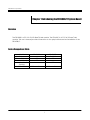
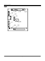
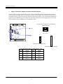
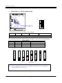
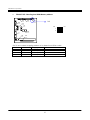
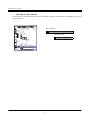
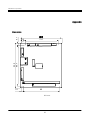
FabIATech Corporation
IPC Solution
Website: http://www.fabiatech.com
Email: [email protected]
FB1603B/C- PC/104
LAN Module User’s Manual
July 2004
Version: 1.1
Part Number:
FB1603B/C
Copyright
©Copyright 2001FabIATech Corporation. The content of this publication may not be
reproduced in any part or as a whole, transcribed, stored in a retrieval system, translated
into any language, or transcribed in any form or by any means, electronic, mechanical,
magnetic etc. or otherwise without the prior written permission of FabIATech Corporation.
Disclaimer
FabIATech makes no representation of warranties with respect to the contents of this
publication. In an effort to continuously improve the product and add features,
FabIATech reserves the right to revise the publication or change specifications contained
in it from time to time without prior notice of any kind from time to time.
FabIATech shall not be reliable for technical or editorial errors or omissions, which may
occur in this document. FabIATech shall not be reliable for any indirect, special, incidental
or consequential damages resulting from the furnishing, performance, or use of this
document.
Trademarks
Trademarks, brand names and products names mentioned in this publication are used for
identification purpose only and are the properties of their respective owners.
Technical Support
If you have problems or difficulties in using the system board, or setting up the relevant
devices, and software that are not explained in this manual, please contact our service
engineer for service, or send email to [email protected].
Returning Your Board For Service & Technical Support
If your board requires servicing, contact the dealer from whom you purchased the
product for service information. You can help assure efficient servicing of your product by
following these guidelines:
A list of your name, address, telephone, facsimile number, or email address where
you may be reached during the day
Description of you peripheral attachments
Description of you software (operating system, version, application software, etc.)
and BIOS configuration
Description of the symptoms (Extract wording any message)
For updated BIOS, drivers, manuals, or product information, please visit us at
www.fabiatech.com
ii
Table of Content
FB-1603B/C PC/104LAN Module User’s Manual ..................................................................................... i
Chapter 1 Introducing the FB1603B/C System Board ........................................................................... 1
Overview...............................................................................................................................................1
Series Comparison Table ....................................................................................................................1
Layout....................................................................................................................................................2
Specifications .......................................................................................................................................3
Packing List ...........................................................................................................................................4
Chapter 2 Hardware Installation ............................................................................................................ 6
Before Installation ................................................................................................................................6
Hardware Features..............................................................................................................................7
CN4 & J1: RJ45 LAN /Adapter Connector with LED indicators .................................8
FB1603B SW2 & JP1: Selecting address & IRQ ..............................................................9
FB1603C SW1: Selecting boot ROM Memory address ..............................................10
CN5, CN6: PC/104 Connector......................................................................................11
Chapter 3 Driver and Utility ................................................................................................................... 14
FB1603C LAN Driver & Utility .............................................................................................................14
FB1603B LAN Driver Installation Under WIN98 ................................................................................14
FB1603B LAN Driver Setup..............................................................................................18
Chapter 4 Technical Reference ........................................................................................................... 20
Trouble Shooting ................................................................................................................................20
Appendix................................................................................................................................................ 22
Dimension ...........................................................................................................................................22
iii
iv
FabIATech Corporation
Chapter 1 Introducing the FB1603B/C System Board
Overview
The FB1603B is a PC/104 10/100-BaseTX LAN module. The FB1603C is a PC/104 10-BaseT LAN
module. This user’s manual provides information on the physical features and installation of the
FB1603B/C.
Series Comparison Table
Model
Chipset
Ethernet 10 Mbps
Ethernet 100 Mbps
LAN Boot Rom
(Option)
Board Size
FB-1603B
FB-1603C
DM9008
YES
SMsC 91C113
YES
YES
YES
90.2mm x 96mm
90.2mm x 96mm
1
FabIATech Corporation
Layout
CN1
CN2
SW1
CN3
CN4
JP1
SW2
J1
CN5
CN6
2
FabIATech Corporation
Specifications
Stack through PC/104 bus.
10Base-T, DM9008 chipset with RJ-45 connector. (FB1603C)
16 addresses selectable and 8 interrupt level selectable with software configuration.
(FB1603C)
10/100-BaseTX, SMsC 93C113 chipset with RJ-45 connector. (FB1603B)
8 addresses selectable and 8 interrupt level selectable. (FB1603B)
On-Board PLCC socket for LAN boot-ROM. (FB1603B/C)
Operating temperature 0 degree C to 60 degree C.
Up to 95% Humidity non-condensing.
Power Req.: +5v only 0.4A maximum.
PC/104 form-factor (90x96mm/3.6”x3.8”).
3
FabIATech Corporation
Packing List
Upon receiving the package, verify the following things. Should any of the mentioned happens,
contact us for immediate service.
•
Unpack and inspect the FB1603B/C package for possible damage that may occur during
the delivery process.
•
Verify the accessories in the package according to the packing list and see if there is
anything missing or incorrect package is included.
•
If the cable(s) you use to install the FB1603B/C is not supplied from us, please make sure
the specification of the cable(s) is compatible with the FB1603B/C system board.
Note: after you install the FB1603B/C, it is recommended that you keep the
diskette or CD that contains drivers and document files, document copies,
and unused cables in the cartoon for future use.
The following lists the accessories that may be included in your FB1603B/C package. Some
accessories are optional items that are only shipped upon order.
•
One FB1603B/C PC/104 LAN board
•
6-Pin or 10-pin LAN adapter cable with transfer board. (FB4605.FB4605A, Optional)
•
One compact disc containing manual file in PDF format and necessary drivers and
utilities
4
FabIATech Corporation
5
FabIATech Corporation
Chapter 2 Hardware Installation
This chapter introduces the FB1603B/C board connectors and then guides you to apply them for
field application.
Before Installation
Before you install the PC/104 LAN board, make sure you follow the following descriptions.
1. Before removing the board from its anti-static bag, wear an anti-static strap to prevent the
generation of Electricity Static Discharge (ESD). The ESD may be created from human body
that touches the board. It may do damage to the board circuit.
2. Once you have installed the LAN board into the CPU’s PC/104 bus, you can start connect
internal cables. The internal cables are wire leads with plastic female connector that
attached to the board’s connectors. The LAN board’s connectors have many numbers of
pins and are the points of contact between the CPU card and other parts of the computer.
3. When you connect the LAN connectors, be careful with the pin orientations.
6
FabIATech Corporation
Hardware Features
The following lists the connectors and jumpers to install the FB1603B/C.
Item
CN4
CN5
CN6
J1
SW1
SW2
Description
LAN Connector and LED Indicators
64 pin PC/104 connector bus A & B
40 pin PC/104 connector bus C & D
LAN 6/10-pin external header for LAN FB4605 (A) board
Firmware Mapping Address Select (FB1603C)
Base I/O Address & Firmware Mapping Address Select (FB1603B)
7
FabIATech Corporation
CN4 & J1: RJ45 LAN /Adapter Connector with LED indicators
CN4 is a RJ45 connector with 2 LEDs for LAN. The left side LED (green) indicates data is being
accessed and the right side LED (orange) indicates on-line status. (On indicates on-line and off
indicates off-line) J1 provide twist-pair signals of external LAN port, if you use external additional
adapter board (FB4605 (A)) with cable. The following table lists the pin assignments of CN4 and
RJ45 connector on the FB4605 (A) LAN adapter board:
CN1
CN2
CN4 and RJ45 connector on FB4605A
adapter board
SW1
CN3
CN4
CN4
JP1
8
1
(Front View)
SW2
J1
CN5
J1
J1
J1
10
6
CN6
1
FB1603C External Header
1
FB1603B External Header
The following lists the pin assignment of CN4.
CN4
Signal
CN4
Signal
1
TPTX+
5
FBG1
2
TPTX -
6
TPRX -
3
TPRX+
7
FBG2
4
FBG1
8
FBG2
8
FabIATech Corporation
FB1603B SW2 & JP1: Selecting address & IRQ
CN1
CN2
SW1
CN3
CN4
OFF
JP1
1
2
3
4
5
6
SW2
J1
CN5
SW2
CN6
ON
The following lists the switch settings of LAN address.
SW2-1
SW2-2
SW2-3
Mapping I/O Address
Remark
Off
Off
Off
300H
Default
Others is reserved
SW2-5 and SW2-6 are use to select mapping address of on-board boot-ROM socket.
SW2-5
Off
On
Off
On
SW2-6
Off
Off
On
On
IRQ3
IRQ4
Remark
Default
Mapping Address
None (Disable)
C800H:0 (8Kbytes)
C800H:0 (8Kbytes
C800H:0 (8Kbytes
IRQ5
IRQ9
IRQ10
IRQ11
IRQ12
IRQ15
Factory Preset
Note: When assign IRQ# selected the system BOIS CMOS SET UP “PLUG AND PLAY”
resource IRQ# must set to ISA
9
FabIATech Corporation
FB1603C SW1: Selecting boot ROM Memory address
CN1
CN2
SW1
SW1
CN3
CN4
JP1
OFF
1
2
SW2
J1
CN5
CN6
SW1 is use to select mapping address of on-board boot-ROM socket.
SW1-1
Off
On
Off
On
SW1-2
Off
Off
On
On
Remark
Default
Mapping Address
None (Disable)
C800H:0 (8Kbytes)
C800H:0 (8Kbytes
C800H:0 (8Kbytes
10
ON
FabIATech Corporation
CN5, CN6: PC/104 Connector
Locate the PC/104 bus connector on the FB1603B/C LAN module and its counterpart on the CPU
card or board.
CN1
CN2
CN5 – BUS A & B
SW1
CN3
CN4
JP1
CN6 – BUS C & D
SW2
J1
CN5
CN6
11
FabIATech Corporation
PC/104 A&B Pin
Pin
Signal
A1
-IOCHK
A2
SD7
A3
SD6
A4
SD5
A5
SD4
A6
SD3
A7
SD2
A8
SD1
A9
SD0
A10
IORDY
A11
AEN
A12
SA19
A13
SA18
A14
SA17
A15
SA16
A16
SA15
Pin
A17
A18
A19
A20
A21
A22
A23
A24
A25
A26
A27
A28
A29
A30
A31
A32
PC/104 C& D Pin
Signal
Pin
C1
GND
C2
SBHE
C3
LA23
C4
LA22
C5
LA21
C6
LA20
C7
LA19
C8
LA18
C9
LA17
C10 MEMR#
Pin
Signal
C11 MEMW#
C12
SD8
C13
SD9
C24
SD10
C25
SD11
C26
SD12
C27
SD13
C28
SD14
C29
SD15
C20
KEY
Signal
SA14
SA13
SA12
SA11
SA10
SA9
SA8
SA7
SA6
SA5
SA4
SA3
SA2
SA1
SA0
Ground
Pin
B1
B2
B3
B4
B5
B6
B7
B8
B9
B10
B11
B12
B13
B14
B15
B16
Signal
Ground
RSTDRV
+5V
IRQ9
-5V (*1)
DRQ2
-12V (*1)
-ZWS
+12V
Key1
-MEMW
-MEMR
-IOW
-IOR
-DACK3
DRQ3
Pin
B17
B18
B19
B20
B21
B22
B23
B24
B25
B26
B27
B28
B29
B30
B31
B32
Pin
Signal
Pin
D1
Ground
D11
D2 MEMCS16# D12
D3
IOCS16# D13
D4
IRQ10
D14
D5
IRQ11
D15
D6
IRQ12
D16
D7
IRQ15
D17
D8
IRQ14
D18
D9
DACK#0
D19
D10
DREQ0
D20
12
Signal
-DACK1
DRQ1
-REFSH
BUSCLK
IRQ7
IRQ6
IRQ5
IRQ4
IRQ3
-DACK2
TC
ALE
+5V
OSC
Ground
Ground
Signal
-DACK#5
DREQ5
DACK#6
DREQ6
DACK#7
DREQ7
VCC
MASTER#
GND
GND
FabIATech Corporation
13
FabIATech Corporation
Chapter 3 Driver and Utility
The FB1603B/C provides a CD ROM includes the manual files (a complete manual file) and the
required utility files.
FB1603C LAN Driver & Utility
Step 1: To install the LAN utility, insert the CD ROM into the CD ROM device, and enter
DRIVER>LAN>DM9008. If your system is not equipped with a CD ROM device, copy the
LAN driver from the CD ROM to a 1.44” diskette.
Step 2 Execute install.exe file.
Note: In the DM9008 directory, an A.EXE file is included to provide installation information and driver.
FB1603B LAN Driver Installation Under WIN98
The following section describes the procedure installation WINDOWS 98 drivers for FB1603B.
1.
Under Windows 98, Click Control Panel, then Add New Hardware.
14
FabIATech Corporation
2.
Windows will start to search for new drivers for the Ethernet controllers, In the Add New Hard
Wizard, click Next button.
3.
Now, Select No, I want to select the hardware form list, and click Next button.
15
FabIATech Corporation
4.
Select Network adapters and click Next button.
5.
Select specify the path of the drivers and then click next button.
16
FabIATech Corporation
6.
Select LAN9000 Ethernet Adapter (ISA) device then click OK.
7.
After files copying is done, click Finish and restart the computer when prompted.
17
FabIATech Corporation
FB1603B LAN Driver Setup
1.
Under Windows 98, Click Control Panel, then click Network, then click select LAN9000 Ethernet
Adapter (ISA).
2.
Select Resources then can configuration Interrupt (IRQ) and click OK.
18
FabIATech Corporation
19
FabIATech Corporation
Chapter 4 Technical Reference
This section outlines the errors that may occur when you operate the system,
and also gives you the suggestions on solving the problems.
Topic include:
Trouble Shooting
Trouble Shooting
The following information informs the error beep code and troubleshooting. Please adjust your
systems according to the messages below. Make sure all the components and connectors are
in proper position and firmly attached. If the errors still exist, please contact with your distributor
for maintenance.
If you have problems after installation, check the following to determine the cause.
Ensure that all cable are properly connected, all plugs are firmly seated in their sockets.
Check to see if the LAN is firmly seated in its bus PC/104. Be sure it is not making contact
with any other cards in the system.
Check the length and rating of connecting cables.
Check CMOS SETUP “PCI PLUG AND PLAY “ RESOURCE IRQ Ensure that must set to ISA
settings. Like below:
20
FabIATech Corporation
If you LAN board IRQ (JP1) selected to IRQ10 the under CMOS SEUP PCI PLUG AND PLAY “IRQ-10
assigned to: Legacy ISA”
If checking these items does not locate the problem, there may be a malfunction of the
computer system, display monitor or the LAN. Consult you computer dealer for assistance in
locating the problem
21
FabIATech Corporation
Appendix
8.9
73.7
95.9
85.7
5.1
Dimension
5.1
80
Unit: mm
22