1
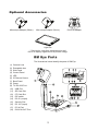
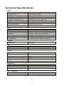
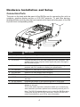
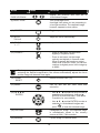
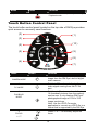
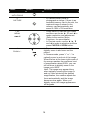
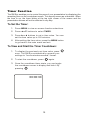
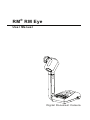
RM ® RM Eye
User Manual
Digital Document Camera
P/N 300AACEN
Made in Taiwan
FCC NOTICE (Class B)
This device has been tested and found to comply with the limits for a Class B
digital device, pursuant to Part 15 of the FCC Rules. These limits are designed to
provide reasonable protection against harmful interference in a commercial,
industrial or business environment. This equipment can generate, use and
radiate radio frequency energy and, if not installed and used in accordance with the
instruction, may cause harmful interference to radio communications. However, there is no
guarantee that interference will not occur in a particular installation. If this equipment does
cause harmful interference to radio or television reception, which can be determined by
turning the equipment off and on, the user is encouraged to try to correct the interference by
one or more of the following measures:
•
•
•
Reorient or relocate the receiving antenna.
Increase the separation between the equipment and receiver.
Connect the equipment into an outlet on a circuit different from that to which the
receiver is connected.
• Consult RM or an experienced radio/TV technician for help.
This device complies with Part 15 of the FCC Rules. Operation is subject to the following two
conditions: (1) this device may not cause harmful interference, and (2) this device must
accept any interference received, including interference that may cause undesired operation.
C AU T I O N O N M O D I F I C AT I O N S
To comply with the limits for the Class B digital device, pursuant to Part 15 of the FCC Rules,
this device must be installed in computer equipment certified to comply with the Class B
limits. All cables used to connect the computer and peripherals must be shielded and
grounded. Operation with non-certified computers or non-shielded cables may result in
interference to radio or television reception.
Any changes or modifications not expressly approved by the grantee of this device could
void the user's authority to operate the equipment.
CE NOTICE
This is a Class B product.
D I S C L AI M E R
No warranty or representation, either expressed or implied, is made with respect to the
contents of this documentation, its quality, performance, merchantability, or fitness for a
particular purpose. Information presented in this documentation has been carefully checked
for reliability; however, no responsibility is assumed for inaccuracies. The information
contained in this documentation is subject to change without notice.
In no event will RM be liable for direct, indirect, special, incidental, or consequential
damages arising out of the use or inability to use this product or documentation, even if
advised of the possibility of such damages.
THE MARK OF CROSSED-OUT WHEELED BIN INDICATES THAT THIS
PRODUCT MUST NOT BE DISPOSED OF WITH YOUR OTHER WASTE.
INSTEAD, YOU NEED TO DISPOSE OF THE WASTE EQUIPMENT BY
HANDING IT OVER TO A DESIGNATED COLLECTION POINT FOR THE
RECYCLING OF WASTE ELECTRICAL AND ELECTRONIC EQUIPMENT.
FOR MORE INFORMATION ABOUT WHERE TO DROP OFF YOUR
WASTE EQUIPMENT FOR RECYCLING, PLEASE CONTACT YOUR
WASTE DISPOSAL SERVICE OR WHERE YOU PURCHASED THE
PRODUCT.
Battery Safety Information
-
Store the batteries in a cool dry place.
Do not dispose of used batteries in normal waste. Dispose of batteries at special
collection points or return to point of sale if applies.
Remove the batteries during long periods of non-use. Always remove exhausted
batteries from the remote control. Battery leakage and corrosion can damage this
remote control, dispose of batteries safely.
Do not mix old and new batteries.
Do not mix different types of batteries: alkaline, standard (carbon-zinc) or
rechargeable (nickel-cadmium).
Do not dispose of batteries in a fire. The batteries may explode or leak.
Never short circuit the battery terminals.
Table of Contents
Introduction ........................................................................................ 1
Package Contents .............................................................................. 1
Optional Accessories......................................................................... 2
RM Eye Parts ...................................................................................... 2
Technical Specifications.................................................................... 3
Hardware Installation and Setup ...................................................... 4
Connection Ports...................................................................................... 4
Setting the DIP Switch ............................................................................. 5
Connecting a VGA, Mac Display Monitor or LCD/DLP Projector.............. 5
Connecting a TV ...................................................................................... 5
Connecting an IBM Compatible PC or Macintosh Computer.................... 6
Inserting and Ejecting the Memory Card .................................................. 6
Transferring the Pictures to a Computer via USB Connection ................. 6
Using RM Eye as USB PC Cam............................................................... 7
Installing the LED Lamp ........................................................................... 7
Connecting the Power Adapter ................................................................ 7
Installing the Optional Light Box............................................................... 8
Connecting to a Microscope..................................................................... 8
Making the Adjustments.................................................................... 9
Camera head ........................................................................................... 9
Mechanical Arm........................................................................................ 9
LED Lamp ................................................................................................ 9
LED Panel .............................................................................................. 10
Infrared Sensor ...................................................................................... 10
Using the Infrared Remote Control ................................................ 10
Touch Button Control Panel............................................................ 13
Timer Function ................................................................................. 15
To Set the Timer: .................................................................................... 15
To View and Start the Timer Countdown: ............................................... 15
OSD Navigation Tree........................................................................ 16
Menu Functions................................................................................ 17
Troubleshooting ............................................................................... 20
Contact Information ......................................................................... 20
Introduction
Packa ge Contents
Thank you for purchasing
Eye
®
RM RM
U ser
your RM Eye ™. This
Manu al
visualiser displays any
documents, negatives,
Di gi tal
Docum
ent Came
ra
transparencies and 3D
objects onto a TV, LCD or
User Manual
DLP projector making
presentations simple.
RM Eye is an ideal
RCA Cable
presentation tool for the
academic community.
RM® RM Eye
S-Video Cable
USB Cable
Driver CD
DVI-RGB Cable
REVERSE
ENTER
Remote Control
(batteries included)
Mini Din-9pin to
S-Video/Composite/RS-232
Adapter
LED Lamp
Carrying Case
1
Power Cord
* The power cord will vary
depending on the standard
power outlet of the country
where it is sold.
Power Adapter
Optional Accessories
Microscope Adapter (28mm)
Microscope Adapter (34mm)
DVI/VGA Adapter
Light Box
* Required to view slide, transparencies and
film or to display negative film as positive image.
RM Eye Par ts
The illustrations below identify the parts of RM Eye.
(1) Camera Lens
(2) Extendable Arm
(3) Side Panel
(4) Control Panel
(5) LED
(6) IR Remote Sensor
(7) Back Panel
(8) Power
(9) TV/ RS-232 Port
(10)
USB Port
(11)
SD Card Slot
(12)
CF Card Slot
(13)
DIP switch
(14)
DC 6V (output)
(15)
Security Slot
(16)
DC 12V (input)
(17)
PC IN Port
(18)
DVI/VGA OUT Port
2
Te c h n i c a l S p e c i f i c a t i o n s
Image
Pick-up Device
Effective Pixels
Frame Rate
White Balance (RGB Output only)
Exposure (RGB output only)
Image mode
Effect
Analog RGB output
S-Video, C-Video Output
1/3” progress scan CCD
790K 1024 (H) x 768 (V)
20 fps
Auto/Manual
Auto/ Manual/ Flicker / Night View
Text/ Graphics/ Microscope
Color/ B/W / Negative/ Mirror/ Rotate
XGA 75 Hz; SVGA 75 Hz
NTSC/ PAL
Optics
Lens
Shooting Area
Zooming
Focusing
Power Source
Consumption
F1.8-2.7 AF
380mm x 285mm (max.); 40mm x 30mm (min.)
Optical: 5x, Digital: 8x (Accelerated)
Auto/ Manual
100-220V ~ 1.8A, 50-60 Hz
15 Watts (lamp off); 30Watts (Lamp on)
Lighting
Lamp Type
LED lamp
Input
VGA Input
RS232
15-Pins D-sub (VGA)
9-Pins D-Sub Female
Output
VGA Output
DVI
S-Video
Composite Video
USB
DC 6V Output
DVI to 15pin D-sub (VGA) Cable
DVI-I Type Female
Mini-DIN Jack
RCA Jack
USB Mini B Type
Power Jack
Dimension
Operating
Folded
Weight
220mm x 140mm x 500mm
380mm x 170mm x 55mm
2 kg (about 4.4 lb)
Card Supported
Secure Digital (SD)
Compact Flash (CF)
16~512MB
16~512MB
3
Har dwar e Installation and Setup
Connection Ports
The ports on the back and side panel of the RM Eye are for connecting the unit to a
computer, graphics display monitor or LCD/ DLP projector, TV and other devices.
Illustrated below are the ports that are located at the back and side panel of the RM
Eye with their corresponding labels.
6
DC
V
2
S23
TV/R
SW
DC12
V
SD
PC IN
CF
DVI/V
GA OU
T
Port
Description
1. Security Slot
Connect a Kensington compatible security lock to this slot.
2. DC 12 V (input)
Plug the power adapter in to this Port.
3. PC IN Port
Connect the RM Eye to the VGA output port of the computer. This
enables you to input computer video signal and pass it through to
the DVI/VGA out port.
4. DVI/VGA OUT
Connect it to a VGA/ Mac monitor, LCD/DLP projector, or high-end
projector with DVI interface to display your presentation.
5. CF Card Slot
Insert the CF card with the label facing up.
6. SD Card Slot
Insert the SD card with the label facing up.
7. DIP Switch
Allows you to set the DIP switch configuration settings.
8. USB Port
This port enables you to use RM Eye as a card reader/writer or PC
web cam.
9. DC 6V (output)
Plug the light module or the optional light box in to this port.
10. TV/RS-232
Connect the Mini Din 9-Pin to S-Video/ Composite/ RS-232
Adapter to this port.
The s-video and composite connectors enable you to output your
video camera or preview a picture from a memory card on your TV.
Note: The RS-232 adapter allows you to control the RM Eye using
a computer through an RS-232 connection. Refer to the RS-232
control instructions on your CD for more information.
4
Setting the DIP Switch
The chart below tells you how to set the DIP switch. Turn the power off before
changing the DIP switch setting.
DIP
Switch
UP
DOWN
1
(TV SYSTEM)
NTSC
PAL
2
(VIDEO OUTPUT)
RGB
TV
3-4
(ENGINEERING PORT)
Default
X
Connecting a VGA, Mac Display Monitor or LCD/DLP
Projector
To display a presentation using a DVI/VGA or any graphics display monitor, set the
DIP switch no. 2 to the UP position.
DC
6V
TV/R
S232
SW
SW
LCD Monitor
DC12
V
LCD/DLP
Projector
SD
PC IN
DVI-RGB Cable
(supplied)
CF
DVI/V
GA OU
T
DIP SWITCH
MAC
Monitor Adapter
(optional)
DVI/VGA Adapter
(optional)
DVI/VGA Adapter
(optional)
Mac Monitor
VGA Monitor
DVI Cable
(not supplied)
LCD/DLP Projector
with DVI Interface
Connecting a TV
To display a presentation on TV, set the DIP switch no. 1 to the TV system that you
have (UP for NTSC and DOWN for PAL) and DIP switch no. 2 to the DOWN position.
If you are using a SCART RGB monitor, set the DIP switch no. 1 to the DOWN position
for PAL TV system. (The SCART RGB Cable is provided as an optional accessory
cable with the RM Eye.)
IN
TV/R
DC
S232
6V
SW
DC12
V
S-Video
Connector
SD
PC IN
CF
DVI/V
GA
S-Video Cable
(supplied)
Video Cable
SW
S-VIDEO
OUT
RCA
Connector
SW
(supplied)
VIDEO
RCA to SCART
Cable (optional)
PAL TV SYSTEM
NTSC TV SYSTEM
RS-232
Connector
Television
SCART TV
To Computer COM PORT
Note: The RS-232 adapter allows you to control RM Eye using a computer through an
RS-232 connection. Refer to the RS-232 control.
5
Connecting an IBM Compatible PC or Macintosh Computer
You can connect the RM Eye to an IBM compatible PC, Macintosh, or notebook (laptop)
computer. After physically connecting the unit to your PC, you can display an image on
your computer by pressing the PC button on the unit’s control panel or remote control.
IBM Compatible PC
OR
VGA Cable
(not supplied)
Computer Adapter
(optional)
Macintosh
Plug to Display Card
M AC
Inserting and Ejecting the Memory Card
Insert the card fully with the label facing up until it reaches the end. To remove, pull the
card out. We highly recommend formatting the memory card with the RM Eye.
TV/RS
DC
232
S232
TV/R
6V
DC
DC12
V
PC IN
DC12
V
CF
DVI/V
GA
6V
SW
SW
SD
SD
PC IN
CF
DVI/V
G A OU
OU T
SD Card
(not supplied)
T
CF Card
(not supplied)
Transferring the Pictures to a Computer via USB Connection
USB Port
Laptop
TV
DC
32
/RS2
6V
SW
DC12
SD
V
PC IN
CF
DVI/V
G A OU
T
USB Cable
Computer
(supplied)
Computer
Operating System
Windows 2000 SP4
and XP SP1
Windows Me and
98/98SE
Requirement
No driver is required. Plug the RM Eye into an available
USB port. A new disk icon appears on your system.
You need to install the driver before connecting the unit to
the computer USB port. Insert the Driver CD in the
CD-ROM drive. The installation main screen will
automatically appear and then click Install. (For detailed
mass storage driver installation procedure, see the
instruction provided in the CD and click User Manual.)
6
Using RM Eye as USB PC Cam
For detailed PC Cam driver installation procedures, see the instruction provided in the
CD and click User Manual.
USB Port
Laptop
TV/R
DC
S232
6V
SW
DC12
SD
V
PC IN
CF
DVI/V
G A OU
T
Computer
USB Cable
(supplied)
Installing the LED Lamp
To ensure adequate lighting, focus the light towards the object to balance the
distribution or range of luminance for better image projection.
TURN ON
Snap to hold.
LL
/
FU
S
C
Stretch the arm and
insert the LED lamp.
E
FO
PR
E
V
IE
W
S
U
C
A
TO
U
P
C
FO
S
U
C
M
C
E
AM
U
N
A
R
ZO
O
A
C
P
Press to release
the latch and open.
PLUG HERE
Connecting the Power Adapter
Use a standard 100V~240V AC power source.
Wa l l
Outlet
S232
TV/R
Power Adapter
DC
SW
DC12
V
SD
PC IN
CF
DVI/V
Power Cord
7
GA OU
T
6V
Installing the Optional Light Box
Connecting an optional light box enables you to view x-rays, transparencies and
negative slides.
Light Box
(optional)
Light Box
(optional)
DC
DC12
V
6V
TV/
RS232
SW
PC
SD
IN
DVI/V
GA OU
T
CF
PLUG IT HERE
TURN ON
Connecting to a Microscope
Connecting the RM Eye to a Microscope enables you to examine microscopic objects
on a big screen without straining your eyes. To view microscopic images, you must set
the unit to microscope mode, and then adjust the microscope for a clearer image.
Connect and tighten
all three (3)
screws
R
SC
UN
W
EW
Close-Up Lens
Microscope Adapter
(option)
RE
SC
Microscope
8
Making the Adjustments
This section describes how your can adjust the RM Eye to meet your needs.
Camera head
The camera head can be rotated 125
degrees from left to right. As you
rotate the camera head, the camera
adjusts the focus automatically.
15 degrees
90 degrees
Mechanical Arm
The mechanical arm is designed to
move from almost any angle. Follow
the illustrated safety procedure to
adjust.
195 degrees
Extendable up
to 122mm
(4.8 in) long
120 degrees
60 degrees
LED Lamp
Carefully adjust the light towards the
object.
45 degrees
45 degrees
9
LED Panel
The chart below indicates the different status of RM Eye.
Color
Green
Red
Description
The unit is powered on.
The unit is in standby mode.
Infrared Sensor
When using the remote control, aim it at the Infrared Sensor, which is located on the
front panel of the RM Eye.
U si n g t h e I n f r ar e d Rem o t e C o n t r o l
Use the RM Eye Remote Control to enhance your presentation, switch between three
presentation modes and access additional features. To use the remote control, first
insert the batteries (2 size “AAA” batteries are provided) into the battery compartment at
the back of the remote. Use the illustration and descriptions below to help you use the
remote control.
10
(2)
(3)
(4)
(1)
(20)
(5)
(6)
(19)
REVERSE
(18)
(7)
(17)
(8)
(9)
ENTER
(11)
(16)
(15)
(14)
(12)
(13)
(10)
Name
Button
Function
(1) POWER
Turn the unit on/off.
(2) CAMERA
MODE
Switch to Camera mode and display the
image from the RM Eye’s built-in CCD
camera.
(3) PC MODE
Switch to PC mode and display the video
signal from the RGB input port.
(4) PLAYBACK
MODE
Switch to Playback mode and toggle to
display 16-thumbnail images or the selected
image from the memory source.
To switch to other memory source, RM Eye must be in camera mode then press
MENU > ADVANCED > MEMORY > TYPE > select the source and press
(►ENTER) > press MENU to exit.
(5) EFFECTS
Convert and display the video in BW,
Negative or Color. (camera mode only)
(6) TIMER
Display, start and hide the on-screen display
timer. You can toggle to display or hide the
remaining time when the timer countdown
has started. (See Timer Function for more
details)
(7) REVERSE
REVERSE
Rotate the image by 180°. (camera mode
only)
11
Name
Button
PG UP
(8 & 19)
Function
PG DN
PAGE UP/DOWN
Display the previous and next set of
16-thumbnail images.
(9) NIGHT VIEW
Turn on/off Night View.
Use Night View when you are presenting in
a low-light condition. The captured image
however, appears in slow motion.
(10) FREEZE
Toggle to pause or resume the camera.
(11) AUTO
FOCUS
Adjust the focus automatically.
(12) FOCUS
U/V
Adjust the focus manually.
(13) ZOOM +/ -
- Zoom in and zoom out the picture
digitally in Playback mode.
- Zoom in and zoom out the image
optically and digitally in Camera mode.
When it reaches the maximum optical
zoom level of about 5 times, you can still
continue to digitally zoom in the image up
to 800%.
The image may appear blurry when optically zooming the image in and out. After
achieving the desired magnification, the camera automatically adjusts the focus
and the image will become clear again.
(14) ZOOM
RESET
Return to normal view (1x).
(15) MENU
Call up and exit the OSD main and
sub-menu.
(16) ▲ ▼ ◄ (►
ENTER)
- Use ▲,▼, ◄ and (► ENTER) to make a
selection and adjustment. And use (►
ENTER) to enter sub-menu. (See Menu
Functions, for more details)
ENTER
- Use ▲,▼, ◄ and (► ENTER) to make a
selection in 16-thumbnail images and
press
to view the selected image.
(18) CAPTURE
Photograph an image. The captured image
is automatically stored in the memory
source at 1024 x 768 resolution.
(20) MIRROR
Flip the image in Camera mode.
12
Name
Button
Function
Remove the selected picture permanently in
Playback mode.
(21) DELETE
To u c h B u t t o n C o n t r o l P a n e l
The touch button control panel located on the top side of RM Eye provides
quick access to commonly used functions.
(2)
(1)
(3)
(4)
(10 )
(5)
(9)
(8)
(6)
(7)
Name
Button
1
CAMERA MODE
2
PC MODE
3
PLAYBACK
MODE
4
FOCUS
Function
Switch to Camera mode and display the
image from the RM Eye’s built-in digital
video camera.
Switch to PC mode and display the
video signal coming from the PC IN
port.
Switches to Preview mode and displays
16-thumbnail pictures from the memory
card source. It only displays RM Eye’s
photographed image or 1024 x 768
image resolutions.
Note: Use the JPEG Converter
application to convert any JPEG file to a
format that is supported by the RM Eye.
Press U or V to manually adjust the
focus.
U/V
13
Name
Button
5
Function
Automatically adjust the focus.
AUTO FOCUS
6
CAPTURE
7&9
MENU/
◄▲►▼
8
ZOOM +/ -
- In Camera mode, press to
photograph an image. If there is an
available memory card in the slot, the
captured image is stored in the
memory card automatically and
saved in 1024 x 768 resolution.
- Press MENU to call the OSD menu
and then use the ▲, ►, ▼ and ◄ to
make a selection and adjustment.
(Refer to the section; Menu
Functions, for more details.)
- In Preview mode, use the ▲, ►, ▼
and ◄ to make a selection and then
press CAP/FULL SCRN button.
In Preview mode, press “+” or “–“ to
digitally zoom in and zoom out the
picture.
In Camera mode, press “+” or “–“ to
optically zoom in and out of the image.
When the bar at the lower right corner of
the screen reaches the maximum level
of magnification about 500%, you can
still continue to digitally zoom in the
image up to 800%.
Note: The image may appear blurry
when optically zooming the image in
and out. After achieving the desired
magnification, the camera adjusts the
focus automatically and the image
becomes clear again. When you
digitally zoom, the image appearance
will degrade.
14
Timer Function
The RM Eye enables you to control the pace of your presentation by displaying the
remaining time on the countdown screen. This merely serves as a reminder. When
the time is up, the timer blinks at the top right corner of the screen and the
presentation screen will not be affected in any way.
To Set the Timer:
1. Press MENU to view on screen function selections.
2. Press ▲or▼ buttons to select TIMER.
3. Press ►or◄ buttons to set a time value. You can
set the time value up to 120 minutes.
4. After setting the time value, press the MENU button
to go back to the main menu and exit.
To View and Start the Timer Countdown:
1. To display the previously set time value, press
once. The RM Eye automatically converts your
settings to “hours:minutes:seconds” format.
2. To start the countdown, press
again.
3. Once the countdown timer starts, you can toggle
the countdown screen to display and hide it by
pressing
.
00:00:30
15
O S D N a v i g a t i o n Tr e e
RGB VIDEO OUTPUT OSD
BRIGHTNESS
-50
0
50
CONTRAST
MENU
BRIGHTNESS
CONTRAST
ZOOM
TIMER
MODE
EFFECT
DEFAULT
ADVANCED
-50
0
50
ZOOM
OPTICAL
DIGITAL
TIMER : MIN.
0
0
120
MODE
TEXT
GRAPHICS
MICROSCOPE
EFFECT
COLOR
B/W
NEGATIVE
MIRROR
REVERSE
DEFAULT
NO
YES
MANUAL
EXPOSURE
AUTO
MANUAL
FLICKER
NIGHT VIEW
-0
WHITE BALANCE
AUTO
MANUAL
MENU
BASIC
EXPOSURE
WHITE BALANCE
RESOLUTION
LANGUAGE
CARD
USB SELECT
100
FLICKER
50 HZ
60 HZ
MANUAL
RED
BLUE
MEASURE
RESOLUTION
1024 X 768
800 X 600
640 X 480
100
RED
-0
-0
LANGUAGE
ENGLISH
DEUTSCH
FRANCAIS
ITALIANO
ESPAÑOL
POLSKI
日本語
中文
CARD
TYPE
FORMAT
TYPE
SD
CF
FORMAT
NO
YES
USB SELECT
PC CAMERA
MASS STORAGE
16
91
511
66
511
BLUE
TV OUTPUT OSD DISPLAY
TIMER : MIN.
0
0
120
WHITE BALANCE
AUTO
MANUAL
MENU
TIMER
WHITE BALANCE
EXPOSURE
CARD
DEFAULT
RED
MANUAL
RED
BLUE
MEASURE
-0
-0
100
FLICKER
50 HZ
60 HZ
CARD
TYPE
FORMAT
TYPE
SD CARD
CF CARD
DEFAULT
NO
YES
FORMAT
NO
YES
511
66
511
BLUE
MANUAL
EXPOSURE
AUTO
MANUAL
FLICKER
NIGHT VIEW
91
100
-0
Menu Functions
The RM Eye provides MENU functions enabling you to fine-tune your screen display,
set the timer, select OSD language and more. Press the MENU button to call up and
exit from the main menu or sub-menu display. Then use ▲or▼ buttons to select
the items in the menu list. Use (►ENTER) button to enter sub-menu. To adjust the
setting, press ◄or► buttons.
OSD Menu
Description
BRIGHTNESS
-50
0
BRIGHTNESS :
50
CONTRAST
-50
0
CONTRAST :
50
ZOOM
Press ►or◄ buttons to emphasize or reduce the difference
between light and dark conditions. You can adjust the contrast
level up to ±50.
ZOOM :
OPTICAL
DIGITAL
Use ▲or▼ buttons to select between Optical and Digital.
Optical zoom uses the physical lens inside the camera to achieve
the desired magnification, wherein the quality of the image is not
affected. When using digital zoom, it interpolates the pixels to
enlarge the image, which makes the image a bit blurry.
TIMER - MIN.
0
Press ►or◄ buttons to increase or decrease the brightness level
and improve the visibility of the image. You can adjust the
brightness level up to ±50.
0
TIMER :
120
Press ►or◄ buttons to set a time value. You can set the time
value up to 120 minutes. (See Timer Function for more details)
17
OSD Menu
Description
MODE
MODE :
TEXT
GRAPHICS
MICROSCOPE
Use ▲or▼ buttons to select between text, graphics and
microscope image enhancement mode.
In text mode, the RM Eye corrects the intensity of the adjacent
pixel making it more uniform producing sharper and clearer
images. While in graphics mode, the RM Eye adjusts the gradient
of the adjacent pixel that appears to have a smooth image.
Setting it to microscope mode automatically fixes the optical
zoom and displays the microscope image more clearly.
EFFECT
EFFECT :
COLOR
B/W
NEGATIVE
MIRROR
REVERSE
Use ▲or▼ buttons to display the image captured by the camera
into positive (true color), monochrome (black and white),
negative, mirrored image, or rotated image by 180º.
DEFAULT
DEFAULT :
NO
YES
Use ▲or▼ buttons to select YES to restore to original factory
default setting or NO to keep the current setting.
MENU
ADVANCED :
BRIGHTNESS
CONTRAST
ZOOM
TIMER
MODE
EFFECT
DEFAULT
ADVANCED
Press ► to go to the Advanced menu.
MENU
BASIC :
BASIC
EXPOSURE
WHITE BALANCE
RESOLUTION
LANGUAGE
CARD
USB SELECT
Press ► to go to Basic menu.
EXPOSURE
EXPOSURE :
AUTO
MANUAL
FLICKER
NIGHT VIEW
MANUAL
0
50
100
Use ▲or▼ buttons to select between Auto and Manual.
RM Eye allows you to automatically or manually adjust the
camera to determine how much light is required.
If you choose to manually adjust the exposure, press ►or◄
buttons to adjust the exposure level.
If you are presenting in a low-light condition, enable Night View
mode from the remote control, then RM Eye automatically
adjusts the exposure to compensate the adverse condition but
the captured image will appear to be in slow motion.
18
OSD Menu
FLICKER
Description
FLICKER :
50 Hz
60 Hz
Use ▲or▼ buttons to select between 50Hz or 60Hz. Some
display devices cannot handle high refresh rates. The image will
flicker a couple of times as the output is switched to another
refresh rate.
WHITE BALANCE
WHITE BALANCE :
AUTO
MANUAL
Use ▲or▼ buttons to select between Auto and Manual.
RM Eye enables you to automatically or manually adjust the
camera to suit the lighting condition or colour temperature. If
you select to manually adjust the white balance, you can adjust
the Red, Blue or use the system to measure the colour
temperature.
MANUAL
RED
BLUE
MEASURE
RESOLUTION
1024 X 768
800 X 600
640 X 480
LANGUAGE
ENGLISH
DEUTSCH
FRANCAIS
ITALIANO
ESPAÑOL
To obtain a more accurate colour balance, place a sheet of white
paper under the camera. Select MEASURE then press
(►ENTER) button to calibrate the colour temperature. Wait until
a "MEASURE OK" appears at the lower left corner of the
presentation screen.
RESOLUTION :
Use ▲or▼ buttons to choose from 1024x768, 800x600 or
640x480 display resolution then press (►ENTER) to make the
selection. This is available only for RGI and DVI-I video output.
LANGUAGE :
Use ▲or▼ buttons to select from different languages then press
(►ENTER) to make the selection.
POLSKI
日本語
中文
TYPE
CF
SD
TYPE :
Use ▲or▼ buttons to select the source on where to store or view
the image.
FORMAT
NO
YES
USB SELECT
PC CAMERA
MASS STORAGE
FORMAT :
Use ▲or▼ to select NO to exit or YES to format and delete all
the data in the memory source then press (►ENTER).
USB SELECT :
Use ▲or▼ buttons to select the USB function between PC
Camera and Mass Storage.
When RM Eye is connected to PC via USB connection, RM Eye
can function as PC Camera and Mass Storage device to transfer
the captured images to and from the memory source and
computer. With the bundled PC Camera application, you may
use it to record your presentation in AVI format or capture still
image directly to your PC’s hard disk.
19
Tr o u b l e s h o o t i n g
This section provides useful tips describing how to solve common problems while
using the RM Eye.
There is no picture on the presentation screen.
1.
2.
3.
4.
Check all the connectors again as shown in this manual.
Check your display output device remote control’s on/off switch.
Verify the setting of the display output device.
If you are to present using a notebook or computer, you may have to
switch the source to VGA.
I have set up the RM Eye and checked all the connections as specified in
the manual, but I can not get a picture on the preferred presentation screen.
-
Once power is connected. You need to switch RM Eye "ON" from the unit to
display the picture on the presentation screen.
The default camera display resolution setting is on 1024x768. If your output
device does not support this resolution you will not be able to see an image on
your display device. You can simply press the MENU and RIGHT or LEFT
button to the increase or decrease the resolution setting.
The picture on the presentation screen is distorted or the image is blurry.
1. Before doing any adjustments, reset all the picture attributes to the factory
default setting (Refer to the Menu Functions, for more details).
2. Each display device is slightly different from another. Use the Positioning
and Adjustment Control of RM Eye to adjust the picture.
3. Use the Brightness and Contrast menu functions to reduce the distortion.
There is no computer signal on presentation screen.
When you turn on the computer, it will auto-detect the type of monitor you have. During
auto-detection, there won't be any display on your presentation screen. To avoid this
problem, connect your computer and all the necessary cables to the RM Eye first
before you power on your computer.
Contact Infor mation
Tel: 08709 202202
www.rm.com/support
20