1
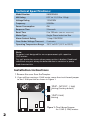
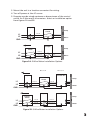
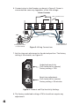
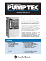
Owners Manual
Pumptec is a microcomputer
microcomputer based
based pump
pump
protection device that continuously
continuously
monitors motor load and power
power line
line
conditions to provide protection
protection against
against
dry well conditions, waterlogged
waterlogged tanks,
tanks,
and abnormal line voltage conditions.
conditions.
Indicator lights provide complete
complete system
system
status, which can be
be easily
easily viewed
viewed
without removing the cover.
cover. Pumptec
Pumptec
interrupts power to the motor
motor whenever
whenever
the motor load drops below a preset
preset
level or the load drops quickly.
quickly.
Pumptec is optimized
optimised to work only
with with
Franklin 2 and
3 wire
single
phase
& 3-wire
single
phase
motors
submersible
motors
0.37 to 1.1(dry
kW.
from 1/3 to 1-1/2
HP.from
An underload
An
underload
(dry
adjustment
is
well)
adjustment
is well)
provided
to address
provided
to address unusual situations.
unusual situations.
Features
Protection Features
• Dry Well (Underload)
• Over & Under Voltage
• Rapid Cycle
• Bound Pump
Indicator Lights
• Load
• Voltage
• Status
Remote Control Features
• Over & Under Load Settings
• Over & Under Voltage Settings
• Reset Time Settings
• Fault History (Last 15 Faults)
• System Status Monitor
Other Features
• Heavy Duty Relay
• 115V/230V 50/60Hz Operation
• Alarm Circuit Contacts
Technical Specifications:
Specifications:
Model Number
5800020600
5800020600
kW
Rating Rating
Horsepower
0.37
1.1 (1/3 to 1.5hp)
1/3 toto1.5
Voltage Rating
115V/230V
Frequency
50/60Hz
50/60Hz
Power Consumption
4W
Response Time
3 Seconds
Reset Time
2 to 120 min. (240 min. w/remote)
w/remote)
Motor Type
Single Phase Induction
Induction Run
Run
Alarm Contact Rating
Rating
1 Amp 115V/230V
Over/Under Voltage
Voltage Time-out
Time-out
2 minutes
Operating Temperature
Temperature Range
Range
-26ºC
to 130ºF
54ºC (-15ºF to 130ºF)
-15ºF to
Note:
Pumptec is not designed for use on permanent split capacitor
(PSC) motors.
Dry well protection occurs when pump suction is broken. Deadhead
conditions may not always be detected due to variation in pump
load characteristics
Installation Instructions
1. Remove the cover from the Pumptec.
60
min
120
min
Timeout
2
min
30 min
15
min
80%
Underload Trip
%SFL
40%
en
e S sitive
or 70%
60%
➭
90%
2. IIff you will be running a 1.5HP
1.1kW motor,
motor, move
move the
the circuit
circuitboard
boardjumper
jumper
to the 1.1kW
position as
as shown
shown in
in Figure
Figure 1.
1.
1.5HP position
1/3HP
- 1.1kW)
1/3 HP––1HP
1 HP(0.37
Setting
Setting
(Factory(Factory
default)default)
M
1.5HP
1.5 HP(1.1kW)
Setting
Setting
Figure 1: C
ircuit board jumper
Circuit
for 1.5HP motors
(1.1kW) motors
2
2
3. Mount the unit in a location convenient for wiring.
4. Turn off power at the AC source.
5. Pumptec may be wired upstream or downstream of the control
switch for 2-wire and 3-wire motors. Select an installation option
from figures 2A and 2B.
Pumptec
Control
Switch
Pump
L1 to L1
L1
L2
Motor to L2
Motor
GND
Pumptec
Control
Switch
Pump
L1 to L1
L1
L2
L2 to L2
Motor
Motor
GND
Figure 2A: 2-Wire Motor Installation Options
Motor to L2
Motor to L2
Pumptec
Control Box
Control
Switch
L1
L2
Pump
L1 to L1
L1 to L1
Motor to L2
L2 to L2
Motor
GND
Pumptec
Control Box
Control
Switch
L1
L2
Pump
L1 to L1
L1 to L1
L2 to L2
Motor to L2
Motor
GND
Figure 2B: 3-Wire Motor Installation Options
3
3
6. Connect wires to the Pumptec as shown in Figure 3. Power is
connected the same way regardless of the line voltage.
Alarm Contacts
Motor Fault Contact
Alarm
L2
Alarm
(1 A
A Max.)
Max.)
(1
Motor
GND
GND
GND
GND
L1
GND
L1
L2
To 2-wire Motor or
3-wire control box
115V or 230V
From power source
or control switch
Figure 3: Wiring Connections
Sensitiv
e
ore 70%
70%
➭
➭
M
M
7. Set the time-out adjustment to the desired position. The factory
setting is 30 minutes, see Figure 4*.
60%
60%
80%
80%
90%
90%
40%
40%
Underload Trip
%SFL
30 min
min
30
15
15
min
min
60
60
min
min
2
2
min
min
120
120
min
min
Underload sensitivity
(Full clockwise for remote)
Factory setting = 70%
Reset time adjustment
(Full clockwise for remote)
Factory setting = 30 minutes
Timeout
Figure 4: Timeout and Trip Sensitivity Settings
8. The factory underload setting of 70% should not require any
adjustment.
4
4
9. Wire in alarm circuit, if desired.
10. Replace cover and secure cover screw.
11. Turn AC power back on.
*Note: If you will be using IR remote control to set the underload and
the time-out settings, set the appropriate adjustment knobs to
the “Remote” position (fully clockwise position). See Figure 4.
The initial remote settings are the same as the factory presets
- 70% for underload and 30 minutes for the underload timeout. The underload adjustment is preset at the factory to detect
underload (dry well) conditions on most systems. In general,
there is no need to adjust this setting.
Operation
Pumptec has three indicator lights labeled POWER, LOAD and VOLTAGE.
If the Pumptec is connected upstream of the pressure switch, the system
status can be determined from these indicator lights at any time. When
wired down stream of the control switch, no status will be displayed
when the control switch is open.
Power Indicator Light
If solid, the Pumptec has power and the system is idle. In this state, the
motor is not running and the Pumptec is waiting for the control device
(i.e. pressure switch) to close and turn on the motor.
When flashing, the system is pumping water and running normally.
Load Indicator Light
When the load light is solid, a dry well (underload) condition has
occurred. The Pumptec will wait the duration of the reset time-out
period before attempting to restart the motor.
The
yellowload
loadlight
lightindicates
indicatesan
one
of the condition
three conditions:
A
flashing
overload
has occurred.
The
unit
must
be
manually
reset
by
removing
power
for
10(underload).
seconds.
1. A solid yellow light with no flicker indicates a dry well
An This
overload
condition
when
motor
current
has
become
is caused
by theoccurs
load of
the the
motor
going
below
the
underload
excessively
high.knob. (If you have a Pumptec remote control, this wil be
adjustment
indicated by underload in the Pumptec Fault History.)
Voltage Indicator Light
2. A solid
yellow light
a slight
flicker
indicates
an underload
When
the voltage
lightwith
is solid,
an under
voltage
condition
has been
causedThe
by aunder
rapidvoltage
decrease
in isload
(approximately
25%
over
a twenty
detected.
trip
factory
preset to 203
volts.
The
second
period).
(If
you
have
a
Pumptec
remote
control,
this
will
remote control feature may be used to alter the under voltage trip be
indicated by underload* in the Pumptec Fault History).
point.
Note: the
In both
conditions
the
will wait
the reset
When
voltage
light is above,
flashing,
anPumptec
over voltage
faultuntil
has been
time-out period
has
endedtrip
before
attempting
theThe
motor.
detected.
The over
voltage
is factory
preset to
to restart
253 volts.
remote
control feature may be used to alter the over voltage trip point.
After a voltage fault has occurred, Pumptec will check the line voltage
every two minutes and will reset when the line voltage returns to the
normal range.
5
5
IfIfsolid,
solid,the
thePumptec
Pumptechas
haspower
powerand
andthe
thesystem
systemisisidle.
idle.InInthis
thisstate,
state,the
the
motor
motorisisnot
notrunning
runningand
andthe
thePumptec
Pumptecisiswaiting
waitingfor
forthe
thecontrol
controldevice
device
(i.e.
(i.e.pressure
pressureswitch)
switch)totoclose
closeand
andturn
turnon
onthe
themotor.
motor.
When
Whenflfl
ashing,
ashing,the
thesystem
systemisispumping
pumpingwater
waterand
andrunning
runningnormally.
normally.
3. A flashing yellow light (on for 1/2 second, off for 1/2 second)
indicates
an overload
Load
Load
Indicator
Indicator
Light
Light caused by the motor current being
excessively
high.
unitamust
be
manually
reset
by removing
When
When
the
theload
load
light
lightThe
isissolid,
solid,
adry
drywell
well
(underload)
(underload)
condition
condition
has
has
power The
for
seconds.
(Ifwait
you
have
a Pumptec
remote
this
occurred.
occurred.
The10
Pumptec
Pumptec
will
will
waitthe
theduration
duration
ofofthe
thereset
resetcontrol,
time-out
time-out
wil be
indicated
by underload
in the
the
Pumptec
period
period
before
before
attempting
attempting
totorestart
restart
themotor.
motor. Fault History.)
AAflfl
ashing
ashingload
loadlight
light
indicatesan
anoverload
overloadcondition
conditionhas
hasoccurred.
occurred.
t*indicates
The
Theunit
unitmust
mustbe
bemanually
manuallyreset
resetby
byremoving
removingpower
powerfor
for10
10seconds.
seconds.
An
Anoverload
overloadcondition
conditionoccurs
occurswhen
whenthe
themotor
motorcurrent
currenthas
hasbecome
become
excessively
excessivelyhigh.
high.
Voltage
VoltageIndicator
IndicatorLight
Light
When
Whenthe
thevoltage
voltagelight
lightisissolid,
solid,an
anunder
undervoltage
voltagecondition
conditionhas
hasbeen
been
detected.
detected.The
Theunder
undervoltage
voltagetrip
tripisisfactory
factorypreset
presettoto203
203volts.
volts.The
The
remote
remotecontrol
controlfeature
featuremay
maybe
beused
usedtotoalter
alterthe
theunder
undervoltage
voltagetrip
trip
point.
point.
When
Whenthe
thevoltage
voltagelight
lightisisflfl
ashing,
ashing,an
anover
overvoltage
voltagefault
faulthas
hasbeen
been
detected.
detected.The
Theover
overvoltage
voltagetrip
tripisisfactory
factorypreset
presettoto253
253volts.
volts.The
Theremote
remote
control
controlfeature
featuremay
maybe
beused
usedtotoalter
alterthe
theover
overvoltage
voltagetrip
trippoint.
point.
After
Afteraavoltage
voltagefault
faulthas
hasoccurred,
occurred,Pumptec
Pumptecwill
willcheck
checkthe
theline
linevoltage
voltage
every
everytwo
twominutes
minutesand
andwill
willreset
resetwhen
whenthe
theline
linevoltage
voltagereturns
returnstotothe
the
normal
normalrange.
range.
Load
Load&&Voltage
VoltageIndicator
IndicatorLights
LightsFlashing
Flashing
both
the
load
and
voltage
indicator
lights
are
When
Whenboth
boththe
theload
loadand
andvoltage
voltageindicator
indicatorlights
lightsare
areflflashing
fl
ashing
ashingtogether
together
together,
aCycle”
“Rapid
Cycle” has
condition
has The
occured.
The will
Pumptec
will
a
a“Rapid
“RapidCycle”
condition
condition
hasoccurred.
occurred.
ThePumptec
Pumptec
willreset
resetafter
afterx x
wait
the duration of the reset time-out period (either the factory
minutes.
minutes.
preset time (30 minutes) or the time set using the underload time-out
adjustment knob by the user) before attempting to restart the motor.
*Note: The
“Rapid Cycle” trip criteria is 4 starts per minute. The
Pumptec must be wired before the pressure switch to activate
the “Rapid Cycle” feature.
66
6
Troubleshooting
Remote Control
A Pocket PC with an infrared port may be used to monitor the motor/
pump system performance and adjust the Pumptec trip points. When
dealing with unusual installations, the system monitor and underload
adjustment remote control features allow quick diagnosis of system
problems.
No Lights
No power is applied to the Pumptec. Check for voltage at the L1 and L2
connections. If Pumptec is wired downstream of the control switch, the
control switch may be open.
Solid Load Light
Pumptec has detected a dry well or underload condition.
A. Make sure the pump and motor are matched correctly.
B. Check for a blocked pump intake or stuck check valve.
C. The coupling between the motor & pump may be stripped.
D. Blocked plumbing or stuck check valve may be causing a
deadhead condition.
E. The underload sensitivity knob may be adjusted in cases where the
unit is too sensitive. After adjustment, check to ensure
insure the unit still
is able to detect a dry well condition.
Flashing Load Light
The system is drawing excessive current.
A. The motor is stalled or there is a ground fault.
Solid or Flashing Voltage Light
The line voltage is too high or too low.
A. An unloaded generator can cause a high line condition.
B. Low line conditions can be caused by loose connections.
C. Report persistent high or low line voltages to the power company.
Flashing Voltage & Load Lights
Rapid Cycle condition has occurred.
A. Check for a waterlogged pressure tank.
B. A bobbing float switch may cause rapid cycling.
7
7
Franklin Electric (Aust) Pty Ltd
106-110 Micro Circuit
Dandenong South, Vic 3175
Tel: +61 3 9799 5000
Toll Free: 1300 FRANKLIN
1300 372 655
franklin-electric.com.au
TOLL FREE HELP FROM A FRIEND
Phone Franklin’s toll-free Submersible
SERVICE HOTLINE for answers to your
installation questions. When you call,
a Franklin expert will offer assistance in
troubleshooting your pump protection
system and provide immediate answers
to your motor application questions.
FE735 1/12
M1502 09/08