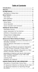
1
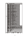
ColorLED 12FC Zoom
ILED-CM-200Z
USER GUIDE
PLEASE READ THESE INSTRUCTIONS CAREFULLY BEFORE USE
CONTENTS
1. Safety Instructions ..........................................................................................2
2. Technical Specifications ..................................................................................4
3. How To Set The Unit ......................................................................................4
3.1 Control panel............................................................................................4
3.2 Main Function...........................................................................................6
4. Control By Universal DMX Controller ..........................................................11
4.1 DMX 512 Connection .............................................................................11
4.2 Address Setting.......................................................................................12
4.3 DMX 512 Configuration..........................................................................13
5. Troubleshooting............................................................................................15
6. Fixture Cleaning............................................................................................16
1A
1. Safety Instructions
WARNING
Please read carefully the instruction, which includes important
information about the installation, usage and maintenance.
y Please keep this User Guide for future consultation. If you sell the unit to another user, be
sure that they also receive this instruction booklet.
y Please unpack and check carefully there is no transportation damage before using the unit.
y Before operating, ensure that the voltage and frequency of power supply match the power
requirements of the unit.
y It’s important to ground the yellow/green conductor to earth in order to avoid electric
shock.
y The unit is for indoor use only. Use only in a dry location.
y The unit must be installed in a location with adequate ventilation, at least 50cm from
adjacent surfaces. Be sure that no ventilation slots are blocked.
y Please disconnect main power before replacement or servicing.
y Please make sure there are no flammable materials close to the unit while operating as it is
fire hazard.
y Please use safety cable when fixes this unit. DO NOT handle the unit by taking its head only,
but always by taking its base.
y Maximum ambient temperature is Ta: 40℃. DO NOT operate it where the temperature is
higher than this.
y Unit surface temperature may reach up to 85℃. DO NOT touch the housing bare-hand
during its operation. Turn off the power and allow about 15 minutes for the unit to cool
down before replacing or serving.
y In the event of serious operating problem, stop using the unit immediately. Never try to
2A
repair the unit by yourself. Repairs carried out by unskilled people can lead to damage or
malfunction. Please contact the nearest authorized technical assistance center. Always use
the same type spare parts.
y DO NOT touch any wire during operation as high voltage might be causing electric shock.
Warning:
y To prevent or reduce the risk of electrical shock or fire, do not expose the unit to rain or
moisture.
y DO NOT open the unit within five minutes after switching off.
y The housing, the lenses, or the ultraviolet filter must be replaced if they are visibly
damaged.
For 230V 50Hz power supply, maximum fixtures that can be connected on one power cable is 8;
For 120V 60Hz power supply, maximum fixtures that can be connected on one power cable is 4;
Caution:
There are no user serviceable parts inside the unit. DO NOT open the housing or attempt
any repairs yourself. In the unlikely event your unit may require service, please contact your
nearest dealer.
Installation:
The unit should be mounted via its screw holes on the bracket. Always ensure that the unit is
firmly fixed to avoid vibration and slipping while operating. And make sure that the structure
to which you are attaching the unit is secure and is able to support a weight of 10 times of
the unit’s weight. Also always use a safety cable that can hold 12 times of the weight of the
unit when installing the fixture.
The equipment must be fixed by professionals. And it must be fixed at a place where is out
of the touch of people and has no one pass by or under it.
3A
2. Technical Specifications
◇ Compact design, fast and powerful LED moving beam wash
◇ DMX512 Control with 14 channels mode
◇ Perfect strobe with smooth dimming 0~100%
◇ Outstanding color macro effect
◇ Blue LCD display for easy navigation
◇ Low heat with long life span for fixture and LEDs
◇Ideal for stage, theatre, TV studio, rental and discotheques
Input Voltage:
Power Consumption:
LED Sources:
Beam Angel:
Dimension:
Weight:
AC 100V~240V, 50/60Hz
198W
OSRAM OSTAR RGBW 12 × 10W LED
10°~60°
263.3×183×340.4mm
7.5Kgs
3. How To Set The Unit
3.1 Control panel
Front View
Rear View
4A
1. Display:
To show the various menus and the selected functions
LED:
2. POWER
On
Power On
3. DMX
On
DMX input present
Button:
4.MENU
To select the programming functions
5.DOWN
To go backward in the selected functions
6. UP
To go forward in the selected functions
7. ENTER
To confirm the selected functions
8. Fuse(T 6.3A):
Protect the unit from damage of the over-current.
9. POWERCON IN:
Connect to a socket (AC 100~240V, 50/60Hz) via the supplied mains cable.
10. POWERCON OUT:
Connect to supply power to the next unit.
11 DMX IN (3-pin XLR):
For DMX512 link, use 3-pin XLR cable to link the unit together.
12 DMX IN (5-pin XLR):
For DMX512 link, use 5-pin XLR cable to link the unit together.
13. DMX OUT (3-pin XLR):
For DMX512 link, use 3-pin XLR cable to link the next unit.
14. DMX OUT (5-pin XLR):
For DMX512 link, use 5-pin XLR cable to link the next unit.
5A
3.2 Main Function
To select any of the given functions, press the MENU button up to when the required one is showing on
the display. Select the function by the ENTER button and the display will blink. Use the DOWN and UP
button to change the mode. Once the required mode has been selected, press the ENTER button to setup,
to go back to the functions without any change press the MENU button again. Hold and press the MENU
button about one second or wait for one minute to exit the menu mode.
The main functions are showing below:
6A
7A
DMX Address
Select DMX Address, press the ENTER button to confirm, the present address will blink on the
display. Use the UP and DOWN button to adjust the address from 1 to 512. Once the address
has been selected, press the ENTER button to setup, to go back to the functions without any
change press the MENU button again. Hold and press the MENU button about one second or
wait for one minute to exit the menu mode.
Dimmer curve
Select Dimmer curve, press the ENTER button to confirm, present mode will blink on the
display. Use the DOWN and UP button to select the Mode1, Mode 2, Mode 3 or Mode 4
mode. Once the mode has been selected, press the ENTER button to setup, to go back to the
functions without any change press the MENU button again. Hold and press the MENU
button about one second or wait for one minute to exit the menu mode.
Mode 1(Optically Linear): The increase in light intensity appears to be linear as DMX value is
increased.
Mode 2(Square Law): Light intensity control is finer at low levels and coarser at high levels.
Mode 3(Inverse Square Law): Light intensity control is coarser at low levels and finger at high
levels.
Mode 4(S-cure): Light intensity control is finger at low levels and high levels and coarser at
medium levels.
8A
Pan Inverse
Select Pan Inverse, press the ENTER button to confirm, present mode will blink on the display.
Use the DOWN and UP button to select the Yes (pan inversion) or No (normal) mode. Once
the mode has been selected, press the ENTER button to setup, to go back to the functions
without any change press the MENU button again. Hold and press the MENU button about
one second or wait for one minute to exit the menu mode.
Tilt Inverse
Select Tilt Inverse, press the ENTER button to confirm, present mode will blink on the display.
Use the DOWN and UP button to select the Yes (tilt inversion) or No (normal) mode. Once
the mode has been selected, press the ENTER button to setup, to go back to the functions
without any change press the MENU button again. Hold and press the MENU button about
one second or wait for one minute to exit the menu mode.
Back Light
Select Back Light, press the ENTER button to confirm, present mode will blink on the display.
Use the DOWN and UP button to select the On (LED on) or Off (LED off) mode. Once the
mode has been selected, press the ENTER button to setup, to go back to the functions
without any change press the MENU button again. Hold and press the MENU button about
one second or wait for one minute to exit the menu mode.
White Balance
Select White Balance, press the ENTER button to confirm, present mode will blink on the
display. Use the DOWN and UP button to select the Red or Green, Blue. Once the mode has
been selected, press the ENTER button to setup, use the DOWN and UP button to adjust the
value (125~255). Once selected, press the ENTER button to setup, go back to the functions
without any change press the MENU button again. Hold and press the MENU button about
one second or wait for one minute to exit the menu mode.
9A
Manual Test
Select Manual Test, press the ENTER button to confirm, present mode will blink on the display.
Use the DOWN and UP button to select the Pan / Tilt / Red / Green / Blue / White /Zoom /
Dimmer or Strobe. Once you find a function or a color you wish to test, press the ENTER
button, use the DOWN and UP button to adjust the values (0~255). Once finished the test,
press the ENTER button to save, go back to the functions without any change press the MENU
button again. Hold and press the MENU button about one second or wait for one minute to
exit the menu mode.
Auto Test
Select Auto Test, press the ENTER button and the unit will run self-test by built-in program. To
go back to the functions press the MENU button again. Hold and press the MENU button
about one second or wait for one minute to exit the menu mode.
Temp.
Select Temp., press the ENTER button and the display will show the temperature of the unit.
To go back to the functions press the MENU button again. Hold and press the MENU button
about one second or wait for one minute to exit the menu mode.
Fixture Time
Select Fixture Time, press the ENTER button and the display will show the number of working
hours of the unit. To go back to the functions press the MENU button again. Hold and press
the MENU button about one second or wait for one minute to exit the menu mode.
Firmware Version
Select Firmware version, press the ENTER button and the display will show the version of
software of the unit. To go back to the functions press the MENU button again. Hold and
press the MENU button about one second or wait for one minute to exit the menu mode.
10A
Reset
Select Reset, press the ENTER button and all channels of the unit will return to their standard
position.,
4. Control By Universal DMX Controller
4.1 DMX 512 Connection
1. If you using a controller with 5 pins DMX output, you need to use a 5 to 3 pin
adapter-cable.
2. At last unit, the DMX cable has to be terminated with a terminator. Solder a 120 ohm
1/4W resistor between pin 2(DMX-) and pin 3(DMX+) into a 3-pin XLR-plug and plug it in
the DMX-output of the last unit.
3. Connect the unit together in a `daisy chain` by XLR plug from the output of the unit to the
11A
input of the next unit. The cable can not branched or split to a `Y` cable. DMX 512 is a
very high-speed signal. Inadequate or damaged cables, soldered joints or corroded
connectors can easily distort the signal and shut down the system.
4. The DMX output and input connectors are pass-through to maintain the DMX circuit,
when one of the units’ power is disconnected.
5. Each lighting unit needs to have an address set to receive the data sent by the controller.
The address number is between 0-511 (usually 0 & 1 are equal to 1).
6. The end of the DMX 512 system should be terminated to reduce signal errors.
7. 3 pin XLR connectors are more popular than 5 pin XLR.
3 pin XLR: Pin 1: GND, Pin 2: Negative signal (-), Pin 3: Positive signal (+)
5 pin XLR: Pin 1: GND, Pin 2: Negative signal (-), Pin 3: Positive signal (+)
Pin 4/Pin 5: Not used.
4.2 Address Setting
If you use a universal DMX controller to control the units, you have to set DMX address from
1 to 512 so that the units can receive DMX signal.
Press MENU button to enter menu mode, select the DMX Address, press ENTER button to
confirm, the present address will blink on the display, use UP and DOWN button to adjust
the address from 001 to 512, press the ENTER button to save. Press the MENU button back to
the last menu or let the unit idle 7 seconds to exit menu mode.
Please refer to the following diagram to address your DMX512 channel for the first 4 units:
Channel mode
Unit 1
Address
Unit 2
Address
Unit 3
Address
Unit 4
Address
14 channels
1
15
29
43
12A
4.3 DMX 512 Configuration
14 Channels Mode:
13A
14A
5. Troubleshooting
Following are a few common problems that may occur during operation. Here are some
suggestions for easy troubleshooting:
A. The unit does not work, no light and the fan does not work
1. Check the connection of power and main fuse.
2. Measure the mains voltage on the main connector.
3. Check the power on LED.
B. Not responding to DMX controller
1. DMX LED should be on. If not, check DMX connectors, cables to see if link properly.
2. If the DMX LED is on and no response to the channel, check the address settings and
DMX polarity.
3. If you have intermittent DMX signal problems, check the pins on connectors or on PCB of
the unit or the previous one.
4. Try to use another DMX controller.
5. Check if the DMX cables run near or run alongside to high voltage cables that may cause
damage or interference to DMX interface circuit.
C. Some units don’t respond to the easy controller
1. You may have a break in the DMX cabling. Check the LED for the response of the master/
slave mode signal.
2. Wrong DMX address in the unit. Set the proper address.
15A
6. Fixture Cleaning
The cleaning of internal and external optical lenses and/or mirrors must be carried out
periodically to optimize light output. Cleaning frequency depends on the environment in
which the fixture operates: damp, smoky or particularly dirty surrounding can cause greater
accumulation of dirt on the unit’s optics.
y Clean with soft cloth using normal glass cleaning fluid.
y Always dry the parts carefully.
y Clean the external optics at least every 20 days. Clean the internal optics at least every
30/60 days.
16A
Declaration of Conformity
We declare that our products (lighting equipments) comply with the following
specification and bears CE mark in accordance with the provision of the
Electromagnetic Compatibility (EMC) Directive 89/336/EEC.
EN55103-1: 2009 ; EN55103-2: 2009; EN62471: 2008;
EN61000-3-2: 2006 + A1:2009 + A2:2009; EN61000-3-3: 2008.
&
Harmonized Standard
EN 60598-1:2008 + All:2009; EN 60598-2-17:1989 + A2:1991; EN
62471:2008; EN 62493: 2010
Safety of household and similar electrical appliances
Part 1: General requirements
PROFESSIONAL LIGHTING TECHNOLOGY
Litecraft is continuously developing and improving all its products. We reserve the right to change
specifications without prior notification. Images are representing but not necessarily a precise product
reference. Litecraft shall be under no liability for any loss, damage or injury for direct or indirect
dependence on the information contained in this guide.