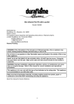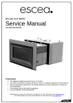
1
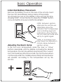
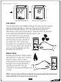
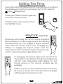
GAS FIRE USER GUIDE
IB600
IB850
IB1100
www.escea.co.nz www.escea.com.au
G8861_6 Userguide NZ/AUS
If the electrical cord is damaged, it must be replaced by the
manufacturer, its service agent or similarly qualified persons in
order to avoid a hazard.
The data label for this appliance, containing technical
information and specifications, can be found adhered to the
metal work under the burners.
DO NOT PLACE ARTICLES ON OR AGAINST THIS APPLIANCE.
DO NOT USE OR STORE FLAMMABLE MATERIALS NEAR THIS APPLIANCE.
DO NOT SPRAY AEROSOLS IN THE VICINITY OF THIS APPLIANCE WHILST IN
OPERATION.
NEVER OPERATE THE FIRE WITH THE FRONT GLASS REMOVED.
IT IS NOT RECOMMENDED TO OPERATE THE FIRE WITH THE FASCIA PANELS
REMOVED.
THIS APPLIANCE IS NOT INTENDED FOR USE BY YOUNG CHILDREN OR INFIRM
PERSONS UNLESS THEY HAVE BEEN ADEQUATELY SUPERVISED BY A
RESPONSIBLE PERSON TO ENSURE THAT THEY CAN USE THE APPLIANCE
SAFELY.
YOUNG CHILDREN SHOULD BE SUPERVISED TO ENSURE THAT THEY DO NOT
PLAY WITH THE APPLIANCE.
THE APPLIANCE MUST BE INSPECTED BEFORE USE AND SERVICED AT LEAST
ANNUALLY BY AN AUTHORISED TECHNICIAN.
THIS APPLIANCE MUST BE INSTALLED IN ACCORDANCE WITH THE
MANUFACTURERS WRITTEN INSTRUCTIONS.
NZ LTD
17 Carnforth St, PO Box 5277
Dunedin, New Zealand
E-mail: [email protected]
Web: www.escea.co.nz
Phone: +64 3 4788220
Distributed in Western Australia by
Distributed in Australia by
Australian Heating Distributors
Glen Dimplex
31 Clune Street
Bayswater, Perth, Western Australia
web: www.escea.com.au
Phone: +61 8 93737000
Unit 2, 205 Abbotts Road
Dandenong, Melbourne
web: www.escea.com.au
Phone: +61 3 87873567
Contents
Remote control Layout
2
Basic Operation
3
Remote Keylock
5
Setting The Remote Time
5
Timer Operation
6
Auxiliary On / Off
8
Overtemp shut off mode
9
Sound & Smell
11
Fascia, Log & Glass Care
13
Trouble shooting
15
Warranty
18
1
Remote Control Layout
1
Display Shows Temperature settings
and status of timers and other functions.
2
On/Off Switches the appliance on
and off.
3
constant low output mode.
1
4
Minus Adjusts the temperature and
time settings down. NOTE: The fan will operate
at its lowest setting.
2
5
3
TO
N LY
FA N
7
BO
T
EF
F
OS
EC
8
Set Time Allows you to set the clock.
7
Fan Boost Puts the fan into a high output
mode.
SE
TI
E
9
ME
TIM
R
LE
CT
AC
E
AT
TI V
8
SET TIME
9
6
Timer Select
Allows you to program
in advance the times you wish to automatically
turn the fire on and off.
6
R
4
5
Flame effect Places the fire in a
Plus
Adjusts the Temperature and time
settings up.
Activate Timer Enables the
timers.
3 + 7
Key Lock Enables and disables the
remotes key lock
Display Layout
C
Room and Set
temperature
display
Flame Effect
indicator
ROOM
SET
Low battery
indicator
LOW
FLAME
EFFECT
ONLY
Room or Set
temperature indicator
Fan Boost indicator
FAN
BOOST
TIMER SET
SET CLOCK
AM ON 1
PM OFF 2
Hour and minute
display
Time & timer AM/PM indicator
Timer Indicator
Clock adjust indicator
Active timer indicator
Timer On / Off time indicator
2
Basic Operation
Initial Start/Battery Placement.
ON
LY
FA N
BO
R
T
EF
CT
NOTE: Between ignition
attempts the remote will
alternately show the
remote’s “Set ” temperature
and a rotating segment
indicator to show that the
fire is in start up mode and
will tr y to ignite again.
OS
FE
Remove the battery cover on the rear of the remote. Insert
the new “AA” size batteries, being careful of the polarity.
You should now see on the display of the remote the time
showing “0:00”. To turn the fire on, press the “POWER” button
once, and within a few seconds the fire will light.
E
SE
TI
ME
TIM
R
LE
CT
AC
E
AT
TI V
SET TIME
Adjusting the Room Temp
NOTE: In Australian fires
only there is a statutor y 5
minute delay between
ignition retries.
To set the room temperature, press the ‘plus’ or ‘minus’
buttons repeatedly until the display is showing the desired
temperature. The remote will then revert back to the ‘current’
room temperature after 30 seconds. The front burner will run
continuously whilst the middle (where fitted) and rear burner
will operate according to the temperature set by the
remote.
C
SET
O
FA N
BO
R
T
EF
CT
OS
FE
PM
N LY
E
SE
TI
ME
TIM
R
LE
CT
AC
E
AT
TI V
SET TIME
3
Basic Operation Continued...
C
C
ROOM
SET
PM
PM
Set temperature
Room Temperature
Fan Boost
The fire has three FAN SPEED settings. The first low fan speed
will run automatically on start-up. The second fan speed
will automatically switch on or off with the increase or
decrease of the set temperature, and the third fan speed
is an optional FAN BOOST speed, which can
be accessed on your remote.
Pressing the FAN BOOST button
will increase the fan speed to
its maximum. This mode will
increase the circulation of heat
from the fire. When this mode is
not on, the fire will still use fan
speeds one and two.
C
SET
FAN
BOOST
EC
TO
N LY
FA N
BO
O
EF
ST
F
PM
TI
ER
ME
R
TI M
SE
LE
CT
AC
E
AT
TIV
SET TIME
Effect Only
FLAME
EFFECT
ONLY
PM
N LY
FA N
BO
O
R
EF
F
TO
ST
EC
SE
TI
ER
ME
TIM
Pressing the EFFECT ONLY button
will only turn on the front “Flame
Effect” burner. This mode is
intended as an ambient effect,
though some heat will still be
produced and the fan will
operate at its lowest setting in this
mode.
LE
CT
ACT
TE
I VA
SET TIME
NOTE: The fan may continue to operate for a few minutes after the fire has
been switched off to remove any excess heat.
4
Setting The Time
Press and hold the “SET TIME” button for more than two seconds and
this will allow you to set the hour including “AM” or “PM” using the
PLUS or MINUS buttons.
TO
N LY
FA N
BO
R
SE
TI
E
R
ME
TIM
Press the button one more time to exit
the “SET TIME” mode.
T
EF
EC
OS
F
Pressing the “TIME SET” button again will
allow you to set the minutes.
LE
CT
ACT
TE
I VA
SET TIME
Keylock (Optional)
C
ROOM
SET
LOW
F
N LY
FA N
BO
SE
TI
ER
ME
TIM
R
T
EF
TO
OS
EC
LE
CT
ACT
TE
I VA
FA N
BO
EF
F
N LY
R
T
FAN
BOOST
TIMER SET
SET CLOCK
AM ON 1
PM OFF 2
TO
OS
LOW
EC
ME
SE
TI
ER
C
ROOM
SET
FLAME
EFFECT
ONLY
FAN
BOOST
TIMER SET
SET CLOCK
AM ON 1
PM OFF 2
TI M
Should you wish to keep the fire from being tampered
with by children or to discourage people from altering
the temperature you can engage a keylock function
which stops the remote buttons from changing any
settings. To engage the keylock simply press the
“Flame Effect” and “Fan Boost” buttons simultaneously
until the main temperature digits display “LO”.
FLAME
EFFECT
ONLY
LE
CT
ACT
TE
I VA
SET TIME
To disengage the keylock again press and hold the
“Flame Effect” and “Fan Boost” buttons simultaneously
until the main temperature digits display “UL” and
normal access to the remote functions will be
available.
SET TIME
NOTE: The “power” button will still be able to turn the fire
off. But once turned off no functions will be available
until the keylock has been removed.
5
Timer Operation
Timers are a great way of starting the fire when you are not around to
turn it on. The timers can be set so you can wake up or come home to
a warm environment.
TIMER SET
ON 1
ON
CT
LY
FA N
BO
R
T
EF
OS
FE
AM
E
SE
TI
ME
TIM
R
LE
CT
AC
E
AT
TI V
SET TIME
Pressing the TIMER SELECT button again will make the
minute figures start flashing. You will continue to see
the “ON” and the number “1”. This indicates that you
are currently editing the minute that the fire will turn
“ON” for timer “1”. Pressing the PLUS or MINUS
button will change the minute.
TIMER SET
ON 1
ON
LY
FA N
BO
R
T
EF
CT
OS
FE
AM
After pressing the TIMER SELECT button the TIMER SET
indicator and the hour figure on the clock will start
flashing. On the bottom right of the display you will
also see the word “ON” and the number “1”. This
indicates that you are currently editing the hour that
the fire will turn “ON” for timer “1”. Pressing
the PLUS or
MINUS buttonwill change the hour.
E
SE
TI
ME
TIM
R
LE
CT
AC
E
AT
TI V
SET TIME
TIMER SET
ON
LY
FA N
BO
R
T
EF
CT
1
OS
FE
AM OFF
E
SE
TI
ME
TIM
R
LE
CT
AC
SET TIME
E
AT
TI V
Pressing the TIMER SELECT button again will make
the hour figure start flashing once again. Though
now you will see the “OFF” indicator as well as the
number “1”. This indicates that you are currently
editing the hour that the fire will now turn “OFF” for
timer “1”. Pressing the PLUS or MINUS button will
change the hour.
Timer Operation Continued Next Page...
6
Timer Operation Continued...
Again pressing the TIMER SELECT button will start the
minutes flashing for you to finish editing the “OFF”
time for timer 1.
TIMER SET
ON
LY
FA N
Pressing the TIMER SELECT button will begin the
cycle all over again for timer “2”.
BO
R
T
EF
CT
1
OS
FE
AM OFF
E
SE
TI
ME
TIM
R
LE
CT
AC
E
AT
TI V
SET TIME
NOTE: If you do not wish to set timer ‘2’, using the
plus or minus keys, navigate to ‘0:FF’ which you will
find between ‘11:00’ and ‘0:00’. Press ‘Timer Select’
again to exit.
Activate Timer
TIMER SET
1
2
ON
LY
FA N
BO
R
T
EF
CT
OS
FE
PM
E
SE
TI
ME
TIM
R
LE
CT
AC
E
AT
TI V
SET TIME
This option allows you to
activate your selected
times. Pressing once will
activate ‘Timer 1’. Press
twice will activate ‘Timer 2’
and by pressing again
you will activate them both.
TIMER SET
PM
1
2
De-activate Timer
To de-activate the timer, press “Activate Timer” until
“TIMER SET” no longer shows on the screen (will require
between 1 to 3 pushes)
TIMER SET
1
2
ON
LY
FA N
BO
R
T
EF
CT
OS
FE
PM
E
SE
TI
ME
TIM
R
LE
CT
AC
E
AT
TI V
SET TIME
75
Auxiliary On/Off Button
gas fires also have a manual On/Off button
located under the bottom fascia panel as shown below.
.
IB600
IB850 & IB1100
This button should be used if the wireless control becomes lost,
damaged or its batteries are flat. Pushing “AUX on/off” button
once will start the heater and it will run at a medium heat
output setting until “AUX on/off” is pushed again to shut the
heater down.
8
Over Temp Shutoff Operation
(Optional)
By default Escea gas fires continue running at their lowest
setting when the “Room” temperature has reached the
“Set” temperature. However, in some cases the output of
the fire, at its lowest setting, may exceed that which is
needed to keep the room at a steady temperature and
the “Room” temperature may continue climbing above
the “Set” temperature.
Your Escea gas fire has a setting where it will turn off all the
burners once the “Room” temperature exceeds the “Set”
temperature and will re-light the burners when the “Room”
temperature falls back below the “Set” temperature. This is
referred to as the “Overtemp Shut Off Mode”.
To enable “Overtemp Shut Off Mode”, so the fire will turn
off all burners when the “Room” temperature climbs above
the “Set” temperature, you need to follow the steps below to
make the adjustment to your Escea remote.
STEP 1
While the remote is in its “OFF” mode with
only the time showing on the display (as shown
in the picture to the left), press the MINUS,
PLUS and FAN BOOST buttons simultaneously
(as shown below right) until all the
characters on the display light up.
This will put the remote into test mode and
the two big temperature digits should
begin counting from 0 to 99 repeatedly.
LY
FA N
BO
AC
CT
A
TIV
C
SET TIME
ROOM
SET
LOW
FLAME
EFFECT
ONLY
FAN
BOOST
TIMER SET
SET CLOCK
AM ON 1
PM OFF 2
TO
N LY
FA N
BO
OS
EC
R
T
ER
ME
TIM
SE
TI
LE
F
SE
EF
E
R
TE
TIM
TIM
ER
T
EF
ON
OS
FE
PM
CT
LE
CT
ACT
SET TIME
9
TE
I VA
Over Temp Operation Continued...
To turn ON the “Over Temp Shut Off Mode”.
STEP 2
Press the “TIMER SELECT” Button and you will see
that the temperature digits stop counting and
will momentarily display “ON” to confirm the
setting has been made.
C
ROOM
SET
LOW
FLAME
EFFECT
ONLY
FAN
BOOST
TIMER SET
SET CLOCK
TO
N LY
FA N
BO
ME
SE
TI
R
E
To exit the test mode press the
ON/OFF button.
TIM
STEP 3
O
R
EF
EC
ST
F
AM ON 1
PM OFF 2
LE
ACT
CT
TE
I VA
SET TIME
To turn OFF the “Over Temp Shut Off Mode”, so
the burners remain lit when the “Room” temp
reaches and goes above the “Set” temp,
repeat step 1.
STEP 2
Press the “ACTIVATE TIMER” Button and you will
see that the temperature digits stop counting
and will momentarily display “OF” to confirm
the setting has been made.
FLAME
EFFECT
ONLY
C
ROOM
SET
LOW
FAN
BOOST
TIMER SET
SET CLOCK
TO
N LY
FA N
10
R
ME
SE
TI
R
E
To exit the test mode press the
ON/OFF button.
TIM
STEP 3
BO
T
EF
EC
OS
F
AM ON 1
PM OFF 2
LE
CT
AC
SET TIME
E
AT
TIV
Sound & Smell
Note: Each time the fire is lit from cold the glass will fog up with
condensation. This is normal and the condensation will disappear
within a few minutes once the glass heats up.
.
Sounds
.
It is possible that you will hear some sounds from your gas
appliance. This is perfectly normal due to the fact that there are
various types of materials used within your appliance. Listed below
are some examples. These are all normal operating sounds and
should not be considered as defects in your appliance.
.
Fan:
.
Escea gas appliances use electric fans to push heated air further
into the room. It is not unusual for the fan to make a “whirring”
sound when ON. This sound will increase or decrease in volume
depending on the thermostatic settings.
.
Gas Control Valve:
.
As the gas control valves turn ON and OFF, a dull clicking sound
may be audible. These sounds are part of the normal operation of
the fire. When the fire is switched off after being run for a while, there
may be popping and fluttering noises as the residual gas in the
burner burns away. These are normal and should be no cause
for concern.
Appliance Metalwork:
Different types and thicknesses of steel will expand and contract at
different rates resulting in some “creaking” and “ticking” sounds
being heard throughout the heating and cool down cycles.
11
.
Sound & Smell
.
Smells
The first few times the unit is operated after installation, the unit
may release an odour and the flames will appear orange caused
by the curing of the paint, the burning off of the starch in the
ceramic logs and the oils in the metal. This is a temporary curing
process which will disappear with use.
.
A deposit on the inside of the glass, caused by the starch in the
logs may appear as a build up after several uses. If this film is not
removed, it will bake on and may become difficult to remove.
When the glass is cold, remove it (see page 10) and clean the inside
.
with a non-abrasive cleaner.
.
.
WARNING
DO NOT ATTEMPT TO CLEAN THE GLASS WHILE IT IS HOT. NEVER
OPERATE THE UNIT WITH THE GLASS REMOVED.
12
Fascia, Log and Glass Care
If the fire is operated with finger (and other) marks present on
the fascia panels there is a risk of them being burnt into the
fascia paintwork as the fire gets hot from normal running.
The fascia panels should be kept as clean as possible and all
cleaning should be carried out when the fire is off and cold.
NEVER, EVER RUB THE FASCIA
The outside of the fascias must only be cleaned with a damp
cloth. The high temperature silver powder coating that is used
on Escea fascia parts contains certain amounts of aluminium
that when rubbed too hard will oxidise leaving a big black
smudge that cannot be removed.
The glass can be cleaned, inside and out, using most domestic
glass cleaners providing that all residue is removed with a
CLEAN and DRY cloth. Stubborn marks can be cleaned using a
ceramic cook top cleaner.
Cleaning maintenance will need to be carried out whenever
soot builds up on the logs and/or inside of the glass.
If soot build up becomes excessive or regular, then it is
recommended that you contact an authorised Gas Fitter to
service your fire.
13
Fascia, Log and Glass Care
Step 1: Lift off the inner
fascia by pulling the base
of inner fascia out and
lifting it up and off.
Step 2: Unscrew the top glass retainer
and remove it. Take care that the
glass does not fall forwards at this
stage.
Step 3: Lift out glass and
place it carefully aside.
Step 4: Take out log set and gently
brush any soot from log with a soft
hearth brush. The burner tops can
be vacuumed too.
Continued...
14
Fascia, Log and Glass Care
Step 5: Clean the inside and outside of glass with normal glass
cleaning products. Use a CLEAN DRY cloth only. Stubborn marks
may be cleaned with a ceramic glass cleaner.
Step 6:Replace in opposite order and test run heater.
Troubleshooting
gas fires communicate both to and from the fire and
remote. This enables the remote to provide some basic fault finding
information that is useful in diagnosing faults with your gas supply or
flue.
NOTE: The remote will take a minute or two to receive and display
the error from the fire. Pressing the plus or minus keys will update the
remote
Electronics
overtemp.
IB600 - Usually associated with a four sided fascia
being mounted too high resulting in an insufficient air
gap between the lower removable strip and the
bottom of the outer fascia.
All models - This fault may be indicative of the gas
regulator being set too high resulting in excess heat
build up. Note: This error has a permanent lock out
and will require the unit to be reset 10 minutes after
the initial error (Reset means turning the power to the
fire off "at the wall" then on again after a few
seconds).
Continued...
15
Troubleshooting
Flame failure or
power flue trip
Power Flue Unit
NZ Only
(PFU)
The fire has tried to light three times and failed.
- Check gas supply and other gas appliances to see if
they are affected. If you have two separate LPG
cylinders, switch over to the full bottle or contact your
gas supplier. You may need to retry igniting the fire a
few times after re-establishing gas supply.
- Check that there has not been a significant reduction
in air pressure inside the house (such as an extractor
fan in a nearby kitchen) which can pull flue gas back
down through the firebox "snuffing" the flames.
Additionally if the living space is built such that no
adventitious ventilation is available (small gaps around
doors widows etc..) the flow of exhaust gasses may stall
and snuff the flames (this may produce an E3 error
also). This can be checked by opening a nearby
window or door to the outside when the fire is faulting
to see if there is an improvement. In this case it may be
beneficial to add some ventilation to the living space
to balance the air being drawn up the flue.
- Alternatively this may indicate a problem with a PFU
installation. If for any reason the exhaust flow is stalled
or backs up, the pressure switch in the PFU will trip and
shut off the burners. If this flow disruption continues for
longer than the normal ignition period it may cause an
E2 Error. Brief wind gusts may trip the pressure switch
and shut off the burners momentarily but the fire will
attempt to relight immediately after the pressure switch
resets with normal exhaust gas flow.
Continued...
16
Troubleshooting
OR
Draught Diverter
Spill Switch.
The flue is not
drawing properly.
A gust of wind pushing exhaust gases back down the flue
or a significant reduction in air pressure inside the house
which is pulling exhaust gases back down the flue (such
as a extractor fan in a nearby kitchen). Alternatively if the
living space is built such that no adventitious ventilation is
available (small gaps around doors widows etc..) the flow
of exhaust gasses may stall and trip the draught diverter
spill switch (this may produce an E2 error also). In this
case it may be beneficial to add some ventilation to the
living space to balance the air being drawn up the flue.
In the unlikely event that the fans have stalled and the
snap disk on the lid of the fire has tripped this would show
an E3 also. Simply check that the fans are running
normally after resetting and running the fire again. Check
that the flue is not blocked. If none of these things can
be obviously identified please contact your local
installation company to check the flue installation. Ensure
there are no extractor fans operating or some other
factor that would draw air out from the room.
Note: This error has a permanent lock out and will
require the unit to be reset 10 minutes after the initial error
(reset means turning the power to the fire off "at the wall"
then on again after a few seconds).
or
Valve Solenoid
Check Failure
Contact your local
service agent.
or
Valve Overtemp
Error
Temp Sensor
Error
If you are experiencing continual problems please contact your
local service agent.
Power Failure
In the event of power failure the fire will immediately shutdown and the gas
valves will automatically close. If the remote was turned off after the power cut
then the fire will return to standby mode once the electrical supply is restored
until its next use. If however the remote was left in the on mode then the fire will
relight within a few minutes of the electrical supply being restored.
17
Warranty
WARRANTY TERMS & CONDITIONS:
If, and only if, the Product is installed as per ESCEA's installation manual and the
step by step warranty procedure has been followed as per instructions issued by
ESCEA, (documented in the agent manual), and that the product is operated
and maintained in accordance with ESCEA operating and maintenance
instructions, then for the first period of 12 months from the date of purchase
ESCEA will pay the cost of repairing or replacing any part of the Product that is
deemed by ESCEA to be faulty.
For the second period of 12 months from the date of purchase ESCEA will supply
replacement parts only, without charge.
Parts and Labour for the first 12 months:
a) ESCEA at its discretion may modify, adjust, repair or replace the faulty products.
The warranty period on parts and labour shall be for 12 months from the
acceptance date of the Products by the ESCEA retailer.
b) Labour costs will only be reimbursed when ESCEA specified procedure has
been followed, and ESCEA has authorised service work before it was carried out.
Parts for the second 12 months ONLY:
a) ESCEA at its discretion will provide replacement parts to the retailer or service
agent. Faulty parts MUST be returned to ESCEA. The parts only warranty period shall
be for 12 months and will commence 12 months after the acceptance date of
the Products by the ESCEA retailer.
General Terms:
1.All repairs made within the warranty period shall be covered by
warranty for a period of 3 months from the date of completion of the
repair, or for the remainder of the overall product warranty, whichever
is the longer.
2.If the buyer or any other party modifies any part of the Product within
the warranty period without the written consent of ESCEA then the warranty
shall be void. ESCEA may, at their sole discretion, decide that the warranty
is void in relation to any part of the product, which has been modified.
3.Escea must be notified of all warranty claims as soon as possible, but in
any event not later than 2 weeks of becoming aware of the circumstance
giving rise to the claims.
4.Escea's liability in this warranty is limited to the repair and replacement
of faulty parts or workmanship by escea. No other resultant direct or
indirect costs or expenses can be claimed.
18