1
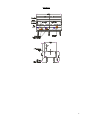
USER’S GUIDE
FOR WOK SERIALS
SPECIFICATION
NAME OF APPLIANCE
SUPERTRON COMMERCIAL WOK
MODEL NO.
1W14R TO 4W14R, 2W14R-1W17R, 2W14R-2R7
MANUFACTURED BY
TU’S BROS PTY LTD
77 MAIN ROAD, CLAYTON SOUTH
VIC 3169 AUSTRALIA
6093
CERTIFICATE NO.
General Description
Unit Model Chinese Wok Table manufactured in single, double or triple units as per order. Each unit has a separate
gas connection. Fluing is carried out by a rectangular slot within the combustion chamber which is then extended up
into the splachback.
The cast iron shroud incorporates a cast wok ring. The 3W14R is a unit consisting of a 3 hole cast wok ring, all of the
same diameter openings but has 3 different burner assemblies.
The left hand side wok consist of a 18 Duck Bill Burner(HP18). The centre wok consists of 24 Mongolian Nozzles
(MBC-24) incorporating a cast iron chimney shroud (3BC Cap). The right hand wok consists of a cast iron double ring
burner incorporating drilled ports. The outer ring and inner ring have individual venturis but are cast as an integral
unit. (KG-8)
HP18
NG
LPG
Duck Bill Burner Left Hand
1.20mm @ 0.90 KPa
0.65mm @ 2.75 KPa
120.0 MJ/h
85.7 MJ/h
Mongolian Nozzle Centre
NG
LPG
1.05mm @ 0.69 KPa
0.55mm @ 2.75 KPa
111.0 MJ/h
90.0 MJ/h
Double Ring Burner -- Right Hand
Inner
Outer
NG
2.10mm/2.80 @ 1.00 Kpa
LPG
1.25mm/1.70 @ 2.75 Kpa
TOTAL
Inner/Outer
22.8/38.8
21.0/35.0
55MJ/h
Port size – Outer Ring – 3mm x 146 ports x 10mm centers
Port size – Inner Ring – 3mm x 72 ports x 8mm centers
Refer to Drawings for burner dimensions and details.
The unit is fully framed in square section tube clad in 304/No4/1.2mm Stainless Steel. Heating is by burner assemblies
as described above.
Ignition to the individual burner assemblies is by means of a pilot light supervised by a flame failure safety device.
The pilot is lit by match or taper.
The burner operations and pilot are controlled by gas cocks located on the front panel. The controls are located so that
they are protected.
Vessel Clearance
Duck Bill Assembly (HP18) – 115mm
Vessel Clearance
Mongolian Nozzle (MBC-24) – 115mm
Vessel Clearance
Double Ring Burner (KG-8) – 115mm
Aeration Control of Burners
HP18 Duck Bill – Fixed Primary Aeration Control
2
MBC-24 Mongolian Nozzle – fixed Primary Aeration Control
KG-8 – Adjustable aeration by rotation of circular metal disc on entrance to enturi.
Secondary Air
Is by means of air drawn up through front control panel and openings around burner and combustion chamber.
Controls
KG-8 Double Ring Burner – Keefer Gas Cock 115B Approval No.2143 (refer drawing for location).
MBC-24 Mongolian Burners – S.I.T. D3 Flame Failure valve Approval No.3530 with thermocouple.
Pilot Cock – Keefer P.T.43 Pilot Valve Approval No.5256.
HP18 Duck Bill Burners – S.I.T. D3 Flame Failure Valve Approval No.3530 with thermocouple. (Refer drawing for
location).
Ball Valve Controls for Duck Bill and Mongolian Burners – ¾" B.S.P. Approval No.5256. (Refer drawing for
location).
Burner Supports
Provided by 25mm x 25mm angle iron and flat mild steel bar welded to main frame.
Fluing
The products of combustion exit out of a slot located in the rear of the combustion chamber 85mm x 280mm cast iron
spigot extious rising into the splashback. The flue risers into the splashback are rectangular 350mm x 40mm x 600mm
x 1.2mm alumised steel, splashbaxk 540mm high and the product of combustion are directed to the front of the unit by
angle slot x 100mm opening full width of the splashback.
Overall Dimensions
Height over Splashback
Width
Depth
Height to Bench
Leg Height
Burner Centers from front ledge of unit
Burner Height above floor
1540mm
1804mm
830mm
740mm
320mm
375mm
400mm
Water Cooling (Hob)
By manual filling of splash deck by operation water tap located on the front panel 1100mm from the right hand side x
110mm down from the top of the bench. The water is drained to a 50mm B.S.P. waste as required.
Water filling
For cooking receptacles is provided by 2 swivel laundry arms controlled by a stop tap on the control panel 50mm x
80mm in from the left hand side. (Run off located in 100mm x 40mm deep channel in the front of unit).
Gas Inlet
A ¾" B.S.P. connection x 420mm above floor and is provided separately to each burner assembly. The connections are
located at the front of the unit as detailed in the drawings.
Gas Regulator
Is provided for each burner assembly (i.e. Wok area) Maxitrol RU48M, Approval No.3088.
Water Drainage (Waste Water Outlet)
50mm – 2 B.S.P. plug & washer located 80mm in front right hand side located in a channel 100mm x 40mm depth.
(For water connections refer to drawings).
Heat Reflector Shield
Located rear of Duck Bill Burner assembly, 440mm x 240mm x 1.2mm aluminized steel.
3
Spillage Trays x 3
1.6 gauge
Width
Depth
Height
520mm
540mm
40mm
Data Plate
Display details N.H.G.C., Test Point Pressure, Injector size, Gas Type, weight.
Manufacturers Name Plate – Located on splashback.
Operating Instructions – Located on control panel.
INSTALLATION INSTRUCTIONS
(By Authorised Personnel Only)
Gas point entry is 420mm above floor and located at the rear of the unit. A 20mm ¾" BSP regulator is supplied with
the unit.
The installer is to supply and fit an isolating gas cock to the appliance for ease of serving the control system. N.B.
Double & Triple units have separate inlet to each control and must have a separate gas cock.
The installer must install the appliance to AG601, 1995 Sections 5-12-4.5 and in accordance with local gas and water
regulations. Clearances from combustible walls sides – Left & Right 250mm. Rear wall 350mm and must be installed
on a fire proof base. Unit may be installed against fire proof walls. Refer installer instructions for special instructions
for this type of installation.
ADDENDA
“The installer must install the appliance to AG601, 1995 Section 5.12.4 and in accordance to local regulations,
attention must be given to Section 5.12.4.4 and 5.12.4.5.
5.12.4.6 Commercial catering equipment on combustible surface, where equipment is installed on a combustible
surface it shall be protected by fire resistant material.
Fire resistant material specifications where appliances are to be installed in non combustible area, the installer must
refer to AG601 and ensure the following side walls and bare walls have materials to the specifications referring to
standards A-S 1530.3 have a zero (0) index for all of the following:
1.
2.
3.
4.
Ignitability
Spread of flame
Heart evolved
Smoked developed
N.B. The thermal resistance not less than 0.05 M20 c/w but in no instance shall the material be of a thickness less than
6mm.”
All models have a 20mm ¾" BSP socket Gas point or compression inlet.
The appliance must be installed as set out in the specifications i.e. Natural gas operating test point pressure 1 KPa.
Water connection 380mm above floor of unit and ½ - 13mm compression to stop tap, located at the rear right hand
side. N.B. Stop tap to be fitted by installer.
Before leaving installation check all gas and water fittings for leaks, and instruct operator in lighting and use of
appliance. N.B. This appliance must always be mounted on 320mm legs as supplied.
If unit fails to operate contact local distributor or call manufacturer.
Phone: (613) 9543 9577
Fax: (613) 9544 1487.
4
OPERATION INSTRUCTION
These instructions should be read carefully prior to operating your Wok Table.
LIGHTING UP OF APPLIANCE
1.
2.
3.
4.
5.
6.
Ensure the isolating gas cock lever is in the ‘On’ position.
Push button marked with star symbol.
Depress flame failure and hold in while lighting pilot for approximately 20 seconds (on new installations
allow for air in pipes to purge out for several seconds).
Release button when pilot light is established.
Turn main burner on by moving lever to ‘On’ position. (If pilot fails to remain alight when main burner
ignites, turn main burner to ‘Off’ position, wait 30 seconds and repeat lighting procedure No.3).
To shut down appliance turn pilot knob to off position or turn off isolating gas cock if vacating premises
for several days.
SERVICE INSTRUCTION
(Must only be carried out by Authorised Personnel)
1.
Clean burners daily, keep burner ports (holes) clean, check every 2 months.
2.
Should a burner need removing, simply remove bolts holding burner to main burner support and draw to
rear of unit and lift through cast ring.
3.
When replacing burner, ensure gas injectors have correct alignment. Jet burner models have fixed
aeration.
4.
Pilot adjustment is by means of removing cap at base of pilot and inserting small screw driver into base
of pilot, screwing clockwise reduces flame (some models have fixed pilot injector – injector changes are
then required for each gas type).
Pilot can also be adjusted through flame failure control adjustment screw on left of front of flame failure
control.
5.
When not using appliance, turn off pilot and gas cocks.
6.
For service in the event of failure of the unit call
Melbourne
(613) 9543 9577
Fax
(613) 9544 1487
Or your local authorized dealer in your state.
5
DIAGRAM
6