1
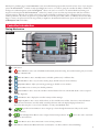
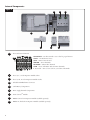
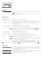
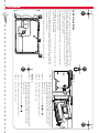
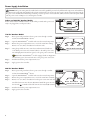
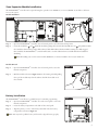
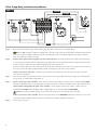
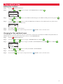
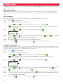
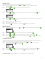
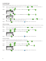
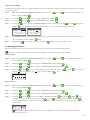
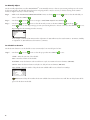
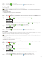
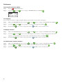
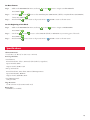
EVOLUTION Series Controller
User’s Guide
TM
i
ii
Table of Contents
Controller Introduction
Timing Mechanism - - - - - - - - - - Internal Components - - - - - - - - - Home Screen Messages - - - - - - - - Setup Screen - - - - - - - - - - - - - Installation
Cabinet Installation/Template - - - - - Power Supply Installation - - - - - - - Zone Expansion Module Installation - - Battery Installation - - - - - - - - - - Valve, Pump Relay and Sensor Installation
Time and Date Setup
Editing Time and Date - - - - - - - - Changing the Time and Date Format - Schedule Setup
Water Days - - - - - - - - - - - - - Schedule Start Setup - - - - - - - - - Zone Runtimes Setup - - - - - - - - - Water Now
Manually Activate a Schedule - - - - - Manually Activate a Specific Zone(s) - - Manually Activate All Zones - - - - - - Water Off
Turn Off Current Operation - - - - - Water Off - - - - - - - - - - - - - - Advanced Functions
Zone Runtimes - - - - - - - - - - - - Zone Details - - - - - - - - - - - - - Schedule Starts - - - - - - - - - - - - -
-
-
-
-
-
-
-
-
-
-
-
-
-
-
-
-
-
-
-
-
-
-
-
-
-
-
-
-
1
2
3
4
-
-
-
-
-
-
-
-
-
-
-
-
-
-
-
-
-
-
-
-
-
-
-
-
-
-
-
-
5
6
7
7
8
- - - - - - - - - - - - - - - - - - - - - - - - - - - - 9
- - - - - - - - - - - - - - - - - - - - - - - - - - - - 9
- - - - - - - - - - - - - - - - - - - - - - - - - - - - 10
- - - - - - - - - - - - - - - - - - - - - - - - - - - - 10
- - - - - - - - - - - - - - - - - - - - - - - - - - - - 11
- - - - - - - - - - - - - - - - - - - - - - - - - - - - 11
- - - - - - - - - - - - - - - - - - - - - - - - - - - - 12
- - - - - - - - - - - - - - - - - - - - - - - - - - - - 12
- - - - - - - - - - - - - - - - - - - - - - - - - - - - 13
- - - - - - - - - - - - - - - - - - - - - - - - - - - - 13
- - - - - - - - - - - - - - - - - - - - - - - - - - - - 14
- - - - - - - - - - - - - - - - - - - - - - - - - - - - 14
- - - - - - - - - - - - - - - - - - - - - - - - - - - - 15
iii
Schedule Details - - - - - - - - - Set Maximum Schedule - - - - Set Schedule Status - - - - - - Set Schedule Type - - - - - - - Weekday Scheduling - - - - Odd Day Scheduling - - - Even Day Scheduling - - - Interval Day Scheduling - - Set Watering Restrictions - - - Set Monthly Adjust - - - - - - Set Schedule as Grow In - - - - Erase Schedule - - - - - - - - Set MV/Pump Delay - - - - - Set Zone Delay - - - - - - - - Set MV/Pump In Delay - - - - Sensors - - - - - - - - - - - - - Diagnostics - - - - - - - - - - - Firmware - - - - - - - - - - - - Firmware Update - - - - - - - - - Factory Reset - - - - - - - - - - - Help/Setup - - - - - - - - - - - - - Alerts - - - - - - - - - - - - - - Contact Toro - - - - - - - - - - - Set Time/Date - - - - - - - - - - Load From USB - - - - - - - - - Save to USB - - - - - - - - - - - Preferences
Set Language - - - - - - - - - Set Display Contrast - - - - - Set Clock Format - - - - - - - Set Date Format - - - - - - - Set the Beginning of the Week - Specifications - - - - - - - - - - - - Electronic Compatibility - - - - - - - Australian Consumer Warranty Statement
Toro Contact Information - - - - - - -
iv
-
-
-
-
-
-
-
-
-
-
-
-
-
-
-
-
-
-
-
-
-
-
-
-
-
-
-
-
-
-
15
15
15
15
16
16
16
17
17
18
18
19
19
19
19
20
20
21
21
21
22
22
22
22
23
23
-
-
-
-
-
-
-
-
-
-
-
-
-
-
-
-
-
-
-
-
-
-
-
-
-
- - - - - 24
- - - - - 24
- - - - - 24
- - - - - 25
- - - - - 25
- - - - - 25
- Back Cover
- Back Cover
- Back Cover
Thank you for purchasing Toro’s new EVOLUTIONTM Series Controller delivering unprecedented control and ease -of -use of your irrigation
system. The EVOLUTIONTM controller is easily expandable from 4 -zones to 8, 12 and 16, giving the controller the ability to handle even
the largest of residential irrigation systems. EVOLUTIONTM allows a rain sensor or soil sensor to be attached further automating your
irrigation needs. Using the bundled EVOLUTIONTM software for your PC, you can use online evapotranspiration (ET) data to further
automate irrigation. And lastly, the controller is housed in a rugged and durable case allowing for years of maintenance -free service and
steadfast performance. If you have any questions or problems with our controller, please call us toll -free at 1 -800 -367 -8676 and we will be
happy to answer your questions and resolve any problem you might have. From International locations, please send your questions to the
[email protected] email address.
Controller Introduction
Timing Mechanism
Figure 1
8
9
1
10
2
11
12
13
3
7
4
5
6
1 – LCD Screen
2 –
Water Off Button. Use to turn off scheduled and manually activated watering. For extended watering off, you can select
1 -14 days or Remains Off.
3 –
Water Now Button. Use to manually activate a schedule, specific zone(s) or All Zones Test.
4 –
Schedules Button. Use to set your active watering day(s), schedule start(s) and zone runtime(s).
5 –
Adjust Water Button. Adjust your watering percentage per schedule or zone runtimes.
6 –
Review Button. Use to review your schedule parameters.
7 –
8 –
9 –
10 –
11 –
Advanced Button. Use to access the controller’s advanced features from zone and schedule details to sensor setup and
controller diagnostics.
Home Button. Use to display the controller’s activity and alert messages.
Help/Setup Button. Use to access and clear alerts, set the controller’s time and date, locate Toro contact information
and local service information, as well as modify controller preferences such as the display language and time and
date format. Use Setup also to save or load a schedule to or from your USB thumb drive.
Up and Down Arrow Buttons. Use to navigate up or down through the menu items. They are also used to
modify parameters.
Left and Right Arrow Buttons. Use to navigate between menu parameters. The
button is also used to revert back
to previous menu selections.
12 –
Select Button. Use to select a menu item or enter and save parameters.
13 – LED Indicator. Indicates that Water Off is active (constantly lit) or an Alert condition is detected (flashing).
1
Internal Components
Figure 2
1
4
5
7
2
3
6
8
97
1 – Zones and Sensor Terminals
VALVE TEST – Use this terminal to test a valve for proper function.
24VAC – 24 VAC Power Source
GND – Power Source Ground
SENSOR – Sensor Terminals
MV PUMP – Master Valve Terminal
COM – Zones’ and Master Valve Common Terminals
1, 2, 3 and 4 – Zone 1, Zone 2, Zone 3, and Zone 4 Terminals
2 – Zones’ 5, 6, 7 and 8 Expansion Module Socket
3 – Zones’ 9, 10, 11 and 12 Expansion Module Socket
4 – Schedules USB Flash Drive Connector
5 – 9 Volt Battery Compartment
6 – Power Supply Terminal Compartment
7 – Smart ConnectTM Module
8 – EMOD -4, Four -Zone Expansion Module (available separately)
9 – EMOD -12, Twelve -Zone Expansion Module (available separately)
2
Home Screen Messages
HOME
01:09PM
WED
01/08
NEXT START
06:00AM
ALERT: PRESS HELP
A
B
C
A Title Bar
The battery icon indicates that the controller’s VAC power is off and the timer is running under
battery power.
HOME
Note: The 9 -volt battery is used to retain schedule parameters and will not activate any zones when
the VAC power supply is off.
B Main Display
TUES
01/08
01:09PM
Displays the current time, day of the week and date.
SCHEDULE A/B/C OR AUX
Indicates which schedule (A, B or C) or auxiliary is associated with the displayed status. If only Schedule
A is active, EVOLUTIONTM will not display the Schedule “A”, “B” and “C” or AUX.
SCHEDULE A
Indicates the displayed schedule is set as Grow In. The Grow In option is set in the Schedule Details
under the Advanced menu.
GROW IN
NOT WATERING TODAY
NOT ACTIVE TODAY
ZONE 1
00:05
Indicates that the displayed schedule will not water that day.
The displayed auxiliary schedule (Aux) will not activate that day.
Indicates that Zone 1 is active with a 5 -minute remaining runtime. Pressing the Right
arrow will
deactivate the running zone and activate the next zone (if additional zones are scheduled) in the schedule
regardless of the remaining runtime.
WATERING COMPLETE
The displayed schedule completed its watering cycle.
SCHEDULE COMPLETE
The displayed auxiliary schedule (Aux) completed its cycle.
NEXT START
06:00AM
Indicates the next start time of the displayed watering or auxiliary (Aux) schedule.
DELAY
00:05
Indicates that the controller is performing a zone delay before the next zone in the schedule is activated.
The zone delay is set in the Schedule Details under the Advanced menu.
SOAK
00:05
Indicates that the active zone is performing a soak delay before continuing operation. The soak delay is
set in the Zone Details under the Advanced menu.
RAIN HOLD
NEXT START
06:00AM
Indicates that the rain sensor is activated and the schedule is delayed until the rain sensor dries up.
If rain delay is set, the controller will indicate Rain Hold until the rain delay expires.
The scroll down arrow indicates that additional information are available. Use the Down
arrow to
reveal the additional message(s).
C Message Bar
ALERT: PRESS HELP
WATER OFF
04 DAYS
SYSTEM OK
Indicates that the controller detected a condition that needs user attention. Check the alert messages in
the Alerts menu under the Help/Setup function. For a list of the Alert messages and description, please
refer to the Alert Messages section on page 22.
Indicates that scheduled watering has been suspended for the indicated days. Watering can be turned off
from 1–14 days, Remains Off or will operate at the next scheduled start.
Indicates that the system is functioning as expected.
3
Setup Screen
SETUP
WELCOME
LANGUAGE
ENGLISH
DATE FORMAT MM/DD/YY
CLOCK
12 HOUR
TIME
12:01AM
DATE
01/01/13
BEGIN WEEK
SUNDAY
INITIALIZING
PLEASE WAIT . . .
Upon power up, the initialization screen will display briefly. On initial power up, the EVOLUTIONTM will display the SETUP screen. This
SETUP screen is only accessed during initial power up or after a factory reset is performed.
Set Language
Select the preferred display language. Select from English, Spanish, French, German, Italian or Portuguese.
Step 1
– While LANGUAGE is selected, press the Right
Step 2
– Use the Up
or Down
Press SELECT
Step 3
– Press the
arrow or SELECT
.
arrows to select from English (default), Spanish, French, German, Italian or Portuguese.
.
HOME button to return to the main screen.
Set Date Format
Step 1
– Use the Down
Step 2
– Use the Up
or Down
Press SELECT
Step 3
– Press the
arrow to select DATE FORMAT. Press the Right
arrow or SELECT
.
arrows to select MM/DD/YY (Month/Day/Year) (default) or DD/MM/YY (Day/Month/Year).
.
HOME button to return to the main screen.
Set Clock Format
Step 1
– Use the Down
Step 2
– Use the Up
Step 3
– Press the
arrow to select CLOCK. Press the Right
or Down
arrow or SELECT
.
arrows to select 12 HOUR (default) or 24 HOUR. Press SELECT
.
HOME button to return to the main screen.
Set the Current Time
Step 1
– Use the Down
Step 2
– Use the Left
arrow to select TIME. Press the Right
or Right
– Press the
.
arrows to navigate between the Hour and Minute positions. Use the Up
arrows to set the correct values. Press SELECT
Step 3
arrow or SELECT
or Down
when finished.
HOME button to return to the main screen.
Set the Current Date
Step 1
– Use the Down
Step 2
– Use the Left
arrow to select DATE. Press the Right
or Right
– Press the
.
arrows to navigate between the Month, Day and Year positions. Use the Up
arrows to set the correct values. Press SELECT
Step 3
arrow or SELECT
or Down
when finished.
HOME button to return to the main screen.
Set the Beginning of the Week
Step 1
– Use the Down
Step 2
– Use the Up
or Down
Press SELECT
Step 3
4
– Press the
arrow to select BEGIN WEEK. Press the Right
arrow or SELECT
.
arrows to select SUNDAY (default) or MONDAY as the beginning of the weekly schedule.
when finished.
HOME button to return to the main screen.
Installation
A
Cabinet Installation
Use this page as a template to mark the screw location of the EVOLUTIONTM cabinet.
There are two mounting options for the EVOLUTIONTM. The first option allows you
to mount the cabinet with three screws and the second option allows you to mount the
cabinet with two screws. For safe and reliable operation, select an installation site that
can provide the following conditions:
• For Indoor model controllers - Inside a garage or other structure that will provide
protection from the weather.
• For Outdoor model controllers - Protection from irrigation spray, wind and snow. A
shaded location is recommended.
• Access to a grounded AC power source (within 4' [1.2 m] for indoor models) that
is not controlled by a switch or utilized by a high current load appliance such as a
refrigerator or air conditioner.
C
B
• Access to the sprinkler control valve wiring and optional accessory wiring.
A
Figure 3
D
C
D
Option 1
Figure 4
Figure 5
B
Step 1 – Unplug the controller panel ribbon cable. Open the front panel about
90º and detach it from the cabinet by pulling the bottom portion
upwards. Removing it from the cabinet allows you to access the
mounting location.
Step 2 – Mark the mounting screw location A , B and D .
Step 3 – Drill 1/8" (3mm) pilot holes at the marked locations.
Step 4 – Secure the cabinet with screws.
Option 2
Step 1 – Unplug the controller panel ribbon cable. Open the front panel about
90º and detach it from the cabinet by pulling the bottom portion
upwards. Removing it from the cabinet allows you to access the
mounting location.
Step 2 – Mark the mounting screw location C and D .
Step 3 – Drill 1/8" (3mm) pilot holes at the marked locations.
Step 4 – Secure the cabinet with screws.
5
Power Supply Installation
WARNING: AC power wiring must be installed and connected by qualified personnel only. All electrical components and installation
procedures must comply with all applicable local and national electrical codes. Some codes may require a means of disconnecting from the
AC power source installed in the fixed wiring and having a contact separation of at least 0.120" (3mm) in the line and neutral poles. Make
sure the power source is OFF prior to connecting the controller.
Indoor and 240 VAC Outdoor Models
Indoor models and the 240 VAC Outdoor model will be pre -wired with a power cord
ready to be plugged into a wall power socket.
110 VAC Outdoor Models
Step 1 – Route power and ground wires from a power source through a conduit
Figure 6
Figure 7
and into the EVOLUTIONTM cabinet.
Step 2
– Open the EVOLUTIONTM controller and access the internal components.
Step 3
– Remove the power compartment cover to access the transformer wiring.
Remove 1/2" (12.7mm) of insulation from the wire ends.
– Using the provided wire nuts, secure the transformer Line (black) wire
to the black power source wire, Neutral (white) to the white power source
wire and Equipment Ground wire (green) to the green power source wire.
Step 4
Step 5
Step 6
6
White
Green
110 VAC Outdoor Models
Note: Earlier EVOLUTIONTM model is equipped with two Equipment
Ground wires (green). Connect both wires to the green power source wire.
– Install and secure the power compartment cover.
– Apply power to the controller.
220 VAC Outdoor Models
Figure 8
Step 1 – Route power and ground wires from a power source through a conduit
TM
and into the EVOLUTION cabinet.
Step 2 – Open the EVOLUTIONTM controller and access the internal components.
Step 3 – Remove the power compartment cover to access the transformer terminals.
Step 4 – Remove 1/2" (12.7mm) of insulation from the power source wire ends and
install the brown wire into the Line (L)terminal. Install the green wire into
Step 5
Step 6
Black
the Ground ( ) terminal and the blue wire into the Neutral (N) terminal.
– Install and secure the power compartment cover.
– Apply power to the controller.
(L)
( )
Brown Green/Yellow
(N)
Blue
220 VAC Outdoor Models
Zone Expansion Module Installation
The EVOLUTIONTM controller can be expanded using the optional 4 -zone (EMOD -4) or 12 -zone (EMOD -12) modules to add more
zones to the system.
Module Installation
Figure 9
Figure 10
B
B
A
A
Step 1
Step 2
– Open the EVOLUTIONTM controller door and control panel to access the internal components.
– Locate the module slot A and B . Install the module by placing the bottom hooked standoffs into slot A and push the module
tab towards the cabinet until a positive click is achieved. The click indicates that the module’s retaining tab is fully engaged.
Once installed, the EVOLUTIONTM controller will be able to read the additional zones and will make them available for
scheduling.
Note: If installing only one four -station module (EMOD -4), it must be installed in the zone 5 -8 module slot.
Module Removal
Step 1
– Open the EVOLUTIONTM controller door and control panel to access the
internal components.
Step 2
– Hold the module as shown in Figure 11. Press the retaining tab while pulling
the top of the module away from the cabinet, then lift the module out of
the controller.
Figure 11
Battery Installation
The EVOLUTIONTM controller uses a 9 -VDC battery for arm -chair programming.
Step 1 – Open the EVOLUTIONTM controller door and control panel to access the
internal components.
Step 2
– Locate the battery compartment at the back of the control panel.
Step 3
– Align the polarity (– and +) of the battery then slide it into the battery
compartment as shown in Figure 12.
Figure 12
–
+
Note: You may need to pull the battery tab forward to align the battery properly.
7
Valve, Pump Relay and Sensor Installation
Figure 13
SENSOR
SENSOR
MV
COM
1
PUMP
2
COM
Step 1
Step 2
Step 3
Step 4
– Route valve wires from the valves, master valves, pump relay and/or sensor into the controller cabinet.
Note: 18 AWG (1.0 mm2) multi -wire sprinkler valve connection cable can be used. This cable is insulated for direct burial
and is color -coded to simplify installation. It can be routed directly into the controller through the access hole provided for
valve wire conduit (if conduit is not used).
– Connect valves, master valves and pump start relay to the valve wires - Connect the white color -coded wire from the cable
to one wire from each valve solenoid and/or pump relay. (Either of the two wires from the solenoid or pump relay can be used
for this connection.) This connection will be designated as the valve common wire.
Connect a separate cable wire to the remaining wire from each valve solenoid. Note the wire color -code used for each valve and
the zone it controls. You will need this information when connecting the valve wires to the controller.
Connect sensor to the valve wires - Connect any two unused color -coded wires to the sensor. Note the color -code of the
sensor wires for installation.
– Secure all wire splices using wire nut connectors. To prevent corrosion and possible short circuits, always use an insulated wire
nut, grease cap or similar waterproofing method.
– Connect valves wires to the controller - Secure the valve common wire (white) to either of the two terminals labeled COM.
Secure the individual valve wires to the appropriate zones they control, Zone 1 valve to terminal 1, Zone 2 valve to terminal 2, etc.
Connect master valve/pump relay wires to the controller - Secure the valve common wire (white) to either of the two
terminals labeled COM. Secure the Master Valve or Pump Relay wire to the terminal labeled MV/PUMP.
Caution: To prevent controller damage, do not connect the pump motor starter directly to the controller.
Connect sensor wires to the controller - Remove the jumper wire from the SENSORS terminals. Secure the two sensor wires
Step 5
8
to the sensor terminals. Refer to the provided sensor instructions for further installation instructions.
– Test for proper operation.
Time and Date Setup
Editing Time and Date
Step 1
– Press the
Step 2
– Use the Up
HELP/SETUP button.
or Down
arrows to navigate to SET TIME/DATE. Press SELECT
.
HELP/SETUP
ALERTS
CONTACT TORO
SET TIME/DATE
LOAD FROM USB
SAVE TO USB
Step 3
– Use the Up
or Right
Step 4
or Down
arrows to select TIME or DATE. Navigate to the TIME or DATE parameters using the Left
arrows.
– Use the Up
or Down
arrows to modify the TIME’s Hour and Minutes or the DATE’s Month, Day and Year (Day,
Month and Year for International Format).
SET TIME/DATE
TIME
DATE
11:25AM
05/01/13
Step 5
– Press SELECT
to save the changes.
Step 6
– Press the BACK
arrow to return to the previous menu or
HOME to return to the main screen.
Changing the Time and Date Format
The EVOLUTIONTM controller display time and date in both the U.S. and International (24 -Hours for TIME and Day/Month/Year for
DATE) formats. To change the time and date format, you have to access PREFERENCES.
Step 1
– Press the
HELP/SETUP button.
Step 2
– Use the Up
or Down
arrows to navigate to PREFERENCES. Press SELECT
Step 3
– Use the Up
or Down
arrows to navigate to CLOCK or DATE FORMAT. Press the Right
.
arrow or SELECT
.
PREFERENCES
LANGUAGE
ENGLISH
CONTRAST
-15
CLOCK
12 HOUR
DATE FORMAT MM/DD/YY
BEGIN WEEK
SUNDAY
Step 4
– Use the Up
or Down
arrows to modify the CLOCK or DATE FORMAT.
Step 5
– Press SELECT
to save the changes.
Step 6
– Press the BACK
arrow to return to the previous menu or
HOME to return to the main screen.
9
Schedule Setup
The EVOLUTIONTM controller displays only one schedule by default. See the Advanced Functions section to activate additional schedules if
needed.
Water Days Setup
The EVOLUTIONTM controller allows for flexible watering by giving you four schedule options: 7 -day, Even days, Odd days or Interval
days. By default, the 7 -day schedule is set for the schedule. To set watering days to Odd, Even or Interval, see the Advanced Functions
section.
7-Day Scheduling
The 7 -day schedule allows you to activate or turn off any of the days in the week. By default, all days are active.
Step 1
– Press the
SCHEDULES button.
Step 2
– (For controllers with multiple active schedules only.)
Use the Up
or Down
arrows to select the Schedule you want to edit. Press SELECT
.
Note: The Schedule and Zone names can be customized using the EVOLUTION Software which can be accessed at
www.toro.com/evolution.
TM
Step 3
– Use the Up
or Down
arrows to navigate to WATER DAYS. Press SELECT
.
SCHEDULE
S
Step 4
M
T
W
T
F
– Use the Left
S
or Right
or turn off
arrows to navigate within the days of the week. Use the Up
or Down
arrows to activate
the day for watering. Repeat for all days of the week.
Step 5
– Press SELECT
to save the changes and return to the SCHEDULES menu.
Step 6
– Press the BACK
arrow to return to the previous menu or
HOME to return to the main screen.
Schedule Start Setup
By default, the EVOLUTIONTM controller is set with 1 start time set to OFF. Additional Starts can be added with a maximum of four starts
per schedule. Once a start is activated, the schedule will activate the first zone (lowest number). Once it is complete, the second zone will
water. The schedule will continue until all zones with runtimes have been activated.
Step 1
– Press the
SCHEDULES button.
Step 2
– (For controllers with multiple active schedules only.)
Use the Up
or Down
arrows to select the Schedule you want to edit. Press SELECT
.
Note: The Schedule name can be customized using the EVOLUTIONTM Software which can be accessed at
www.toro.com/evolution.
Step 3
– Use the Up
or Down
arrows to navigate to SCHEDULE STARTS. Press SELECT
.
SCHEDULE
START
ADD START
01:00AM
EACH START RUNS ALL
SCHEDULED ZONES
Step 4
– Use the Left
or Right
arrows to navigate to the start time’s Hours, Minutes and AM/PM. Use the Up
arrows to set your desired start time. Press SELECT
or Down
to save.
– Navigate to ADD START to add another start time. Press SELECT
Step 6
. Modify the new start time as indicated in Step 3.
– To delete a start time, set the time to OFF. The OFF selection is located between the full hour of 11:00 AM/PM and the full
hour of 12:00 AM/PM (23:00 and 00:00).
Step 7
– Press the BACK
Step 5
10
arrow to return to the previous menu or
HOME to return to the main screen.
Zone Runtimes Setup
The Zone Runtimes is where you select all the zones that will run in the schedule. By default, all zones are set to OFF. Modify the runtime
for each zone as necessary. Deactivate a zone by setting the runtime to OFF.
SCHEDULES button.
Step 1
– Press the
Step 2
– (For controllers with multiple active schedules only.)
Use the Up
or Down
arrows to select the Schedule you want to edit. Press SELECT
. If only Schedule A is
enabled, move to Step 3.
Note: The Schedule and Zone names can be customized using the EVOLUTIONTM Software which can be accessed at
www.toro.com/evolution.
Step 3
– Use the Up
or Down
Step 4
– Use the Up
or Down
arrows to navigate to ZONE RUNTIMES. Press SELECT
.
arrows to navigate to the ZONE you want to set or edit. Press the Right
arrow or SELECT
.
SCHEDULE
ZONE 1
ZONE 2
3:FRONT YARD
4:BACK YARD
ZONE 5
00:15
00:05
00:15
00:20
OFF
Step 5
Step 6
– Use the Up
or Down
arrows to set the desired runtime for that particular zone. Press SELECT
– Repeat Steps 4 and 5 for the remaining Zones. Set the Zone to OFF to disable.
Step 7
– Press the BACK
arrow to return to the previous menu or
to save.
HOME to return to the main screen.
Water Now
Water Now is used to manually activate a schedule, zone(s), or to test all zones.
Manually Activate a Schedule
Step 1
– Press the
WATER NOW button.
Step 2
– Use the Up
or Down
arrows to navigate to SCHEDULE. Press SELECT
The selected schedule will run and activate all assigned zones.
. Watering will begin.
(For controllers with multiple active schedules only.)
Use the Up
or Down
arrows to select the Schedule you want to activate. Press SELECT
.
WATER NOW
SCHEDULE A
SCHEDULE B
ZONES
Note: The Schedule name can be customized using the EVOLUTIONTM Software which can be accessed at
www.toro.com/evolution.
Step 3
– Press
BACK to return to the previous menu or
HOME to return to the main screen.
11
Manually Activate a Specific Zone(s)
Step 1
– Press the
Step 2
– Use the Up
WATER NOW button.
or Down
arrows to navigate to ZONES. Press SELECT
.
Note: The Zone name can be customized using the EVOLUTION Software which can be accessed at
TM
www.toro.com/evolution.
Step 3
– Use the Up
or Down
arrows to select the specific zone to activate. Press the Right
arrow or SELECT
.
WATER NOW
ZONE 1
ZONE 2
ZONE 3
Step 4
OFF
-–:10
OFF
– Use the Up
or Down
arrows to assign the zone a runtime. Press SELECT
.
The zone will activate until the specified runtime expires. A water drop icon is displayed to indicate that the zone is actively
watering.
Step 5
– Repeat Steps 3 and 4 to activate additional zones. Watering will occur in the order that the zones are entered.
Step 6
– Press the BACK
arrow to return to the previous menu or
HOME to return to the main screen.
Manually Activate All Zone Test
Step 1
– Press the
Step 2
– Use the Up
WATER NOW button.
or Down
arrows to navigate to ALL ZONE TEST. Press the Right
arrow or SELECT
.
WATER NOW
SCHEDULE
ZONES
ALL ZONE TEST
Step 3
– Use the Up
02:00
or Down
arrows to assign a runtime. Press SELECT
.
Note: The EVOLUTION controller will sequentially water all active zones (zones with runtimes) starting with Zone 1.
All active zones will run the specified runtime duration.
TM
Step 4
– Press the BACK
arrow to return to the previous menu or
HOME to return to the main screen.
Note: All Zone Test will not affect the AUX schedule. AUX Schedule is normally used for lighting.
12
Water Off
Turn Off Current Operation
Step 1
– Press the
WATER OFF button.
WATER OFF
RESUME WATERING
NEXT SCHEDULED START
All currently active automatic schedule(s) and manually activated schedules and zones will turn off. The EVOLUTIONTM
controller will not run any watering schedules while the WATER OFF screen is displayed.
Step 2
– Press the
HOME button. Irrigation will resume at the next automatic scheduled start time.
Water Off
Step 1
– Press the
WATER OFF button.
All currently active automatic schedule(s) and manually activated schedules and zones will turn off. The EVOLUTIONTM
controller will not run any schedules while the WATER OFF screen is displayed.
Step 2
– Use the Up
or Down
arrows to assign the number of days until watering resumes. Select a delay of 1–14 days, NEXT
SCHEDULED START or REMAINS OFF. Press SELECT
to enter or
HOME to cancel. Pressing SELECT will save
your selection and take you back to the HOME screen.
WATER OFF
RESUME WATERING
IN 05 DAYS
13
Advanced Functions
You can access the EVOLUTIONTM controller’s advanced functions by pressing the
ADVANCED button and then pressing
SELECT button to confirm. In the Advanced Functions, you can activate additional schedules, check and set runtimes and start times to all
schedules in one screen, set schedule and zone details, set rain sensors to the schedules, perform diagnostics test, check firmware version and
reset the controller to factory defaults.
Zone Runtimes
The Zone Runtimes function is where you can set any of the zones to any of the three schedules (A, B and C). All the zones are listed from
least to greatest. You can then set any zone to a schedule by entering a runtime to its corresponding schedule column.
Step 1
– While in the ADVANCED menu, use the Up
or Down
arrows to select the ZONE RUNTIMES. Press SELECT
to access.
Step 2
– Use the Up
or Down
arrows to select the zone you want to edit.
ZONE RUNTIMES
01
02
03
Step 3
A
00:05
00:10
00:05
B
OFF
OFF
OFF
– Use the Left
Down
CC
OFF
OFF
OFF
or Right
arrows to navigate to the runtime you want to edit. Enter runtime using the Up
arrows. Moving to another parameter will save the changes as well as pressing the SELECT
or
button.
Repeat Step 3 as necessary to assign runtimes to other schedules.
Step 4
Step 5
Note: The maximum runtime that you can assign to a zone is 12 hours. Water Adjustment will not increase the runtime
beyond 12 hours.
– Repeat Steps 2 and 3 for the remaining zones as necessary.
– To remove a zone from a schedule, set the runtime to OFF.
Step 6
– Press the BACK
arrow to return to the previous menu or
HOME to return to the main screen.
Note: A schedule will also need a Start Time for the zone to be activated.
Zone Details
Step 1
– While in the ADVANCED menu, use the Up
Press SELECT
or Down
arrows to select the ZONE DETAILS.
to access.
Step 2
– Use the Up
or Down
arrows to select the zone you want edit. Press SELECT
Step 3
– Use the Up
or Down
arrows to select the ZONE DETAILS you want to edit.
.
ZONE 01
MV PUMP
CYCLE
SOAK
Step 4
ON
OFF
OFF
– Use the Right
SELECT
arrow to navigate to the parameter. Use the Up
or Down
arrows to modify its values. Press
to save and select the next zone detail.
MV/PUMP – Set to ON if a master valve is used in conjunction with this zone. Connect the master valve relay to MV PUMP
terminals. If no master valve is used in conjunction with this zone, set to OFF.
CYCLE and SOAK – This function is used to break the zone’s runtime into shorter cycles to allow the water to penetrate the
soil and avoid runoff or wasted water.
The cycle time is the length of time the zone will run before entering a soak time.
The soak time is set as a delay between zone cycles. It is usually used to allow water to penetrate the soil into the root system.
Allowing a soak time prevents water waste from water runoff during irrigation. Water runoff can occur when the applied
irrigation is higher than the absorb rate of the soil being irrigated. The excess water will then accumulate on top of the soil and
will form a runoff stream carrying water away from where it should be applied.
The cycle and soak will repeat in sequential order until the total runtime for the zone has been met.
Step 5
14
– Press the BACK
arrow to return to the previous menu or
HOME to return to the main screen.
Schedule Starts
The Schedule Starts function allows you to view the three schedules with all four possible start times.
Step 1
– While in the ADVANCED menu, use the Up
Press SELECT
Step 2
– Use the Up
or Down
arrows to select the SCHEDULE STARTS.
.
or Down
arrows to navigate to the row that the start time is in.
ZONE RUNTIMES
A
B
04:30A 07:45A
08:00P OFF
OFF
OFF
Step 3
– Use the Left
C
OFF
OFF
OFF
or Right
arrows to navigate to start time you want to edit. You can also press SELECT
until the
desired start time is selected.
ZONE RUNTIMES
A
B
C
04:30A 07:45A OFF
08:00P OFF
OFF
OFF
OFF
OFF
Step 4
– Use the Up
or Down
arrows to enter the desired start time. Moving to another parameter will save the changes as
well as pressing the SELECT
button.
Step 5
– Repeat Steps 2 and 3 to edit or add another start time.
Step 6
– Place the start time to OFF to remove.
Step 7
– Press the BACK
arrow to return to the previous menu or
HOME to return to the main screen.
Schedule Details
Step 1
– While in the ADVANCED menu, use the Up
or Down
arrows to select SCHEDULE DETAILS. Press SELECT
.
SCHEDULE DETAILS
MAX SCHEDULES
SCHEDULE A
SCHEDULE B
SCHEDULE C
AUX 1
1
Step 2
– Use the Up
or Down
arrows to select the schedule you want to edit. Press SELECT
Step 3
– Use the Up
or Down
arrows to select through the menu items you want to edit. Press SELECT
Step 4
– Use the Left
or Right
arrows to navigate to the parameter and use the Up
values. Press SELECT
.
or Down
.
arrows to modify the
to save.
Set Maximum Schedules
The maximum concurrently running schedule is set in Schedule Details. The default setting is 1 schedule. The auxiliary schedule is not
included in the set maximum. You can set a maximum of 1–3 schedules to activate at the same time.
Step 1
– While in the ADVANCED/SCHEDULE DETAILS menu. Use the Up
SCHEDULES. Press the Right
arrow or SELECT
or Down
arrows to select MAX
.
SCHEDULE DETAILS
MAX SCHEDULES
SCHEDULE A
SCHEDULE B
SCHEDULE C
AUX 1
Step 2
– Use the Up
Step 3
– Press the BACK
1
or Down
arrows to set the maximum schedules to activate concurrently. Press SELECT
arrow to return to the previous menu or
to save.
HOME to return to the main screen.
Set Schedule Status – Select the schedule’s mode. Place it in ENABLED (Active) or DISABLED (OFF).
15
Set Schedule Type
Weekday Scheduling
Selecting Weekday scheduling will activate all 7 days of the week. You can disable any of the 7 days as a non -watering day.
Step 1
– While in the ADVANCED/SCHEDULE DETAILS menu, use the Up
want to edit. Press SELECT
Step 2
– Use the Up
or Down
or Down
arrows to select the Schedule you
.
arrows to navigate to TYPE. Press the Right
arrow or SELECT
.
arrows to select WEEKDAY. Press the Right
arrow or SELECT
.
SCHEDULE A
STATUS
ENABLED
TYPE
WEEKDAY
RESTRICTIONS
MONTHLY ADJUST
Step 3
– Use the Up
or Down
WEEKDAY
S
Step 4
M
T
W
F
– Use the Left
or turn off
Step 5
T
S
or Right
arrows to navigate within the days of the week. Use the Up
or Down
arrows to activate
the day for watering. Repeat for all days of the week.
– Press the BACK
arrow to return to the previous menu or
HOME to return to the main screen.
Odd Day Scheduling
Selecting Odd scheduling will activate all odd -numbered days in the calendar as a watering day. The 31st day of the month is not a watering
day.
Step 1
– While in the ADVANCED/SCHEDULE DETAILS menu, use the Up
want to edit. Press SELECT
or Down
arrows to select the Schedule you
.
Step 2
– Use the Up
or Down
arrows to navigate to TYPE. Press the Right
Step 3
– Use the Up
or Down
arrows to select ODD. Press SELECT
arrow or SELECT
.
.
SCHEDULE A
STATUS
ENABLED
TYPE
ODD
RESTRICTIONS
MONTHLY ADJUST
Step 4
– Press the BACK
arrow to return to the previous menu or
HOME to return to the main screen.
Even Day Scheduling
Selecting Even will activate all even -numbered days in the calendar as a watering day.
Step 1
– While in the ADVANCED/SCHEDULE DETAILS menu, use the Up
want to edit. Press SELECT
or Down
arrows to select the Schedule you
.
Step 2
– Use the Up
or Down
arrows to navigate to TYPE. Press SELECT
Step 3
– Use the Up
or Down
arrows to select EVEN. Press the Right
.
arrow or SELECT
.
SCHEDULE A
STATUS
ENABLED
TYPE
EVEN
RESTRICTIONS
MONTHLY ADJUST
Step 4
16
– Press the BACK
arrow to return to the previous menu or
HOME to return to the main screen.
Interval Day Scheduling
Selecting Interval watering allows you to specify the number of days between watering. Selecting an interval of 3 will prompt the controller
to water every 3rd day.
Step 1
– While in the ADVANCED/SCHEDULE DETAILS menu, use the Up
want to edit. Press SELECT
– Use the Up
or Down
arrows to navigate to TYPE. Press SELECT
Step 3
– Use the Up
or Down
arrows to select INTERVAL. Press SELECT
Step 4
– Use the Right
Step 5
.
.
arrow to navigate to WATERS EVERY designation. Modify using the Up
or Down
arrows. Press
to save and advance to the next parameter. Enter 2 for every other day, 3 for every third day, etc.
INTERVAL
INTERVAL
WATERS EVERY 03 DAYS
CURRENT DAY 01
WATERS EVERY 03 DAYS
CURRENT DAY 02
WATERS ON LAST DAY
OF INTERVAL
WATERS ON LAST DAY
OF INTERVAL
– The CURRENT DAY designation represents the present day within the interval schedule. Enter 1 for first day, 2 for second
day, 3 for third day, etc. Press SELECT
Step 6
arrows to select the Schedule you
.
Step 2
SELECT
or Down
to save.
arrow to return to the previous menu or
– Press the BACK
HOME to return to the main screen.
Set Watering Restrictions
Restrictions function allows you to select the day and time frame you do not want any scheduled watering activity.
Note: There is only one time frame that can be set and it will apply to all the restricted days for each schedule.
Restriction Days
Step 1
– While in the ADVANCED/SCHEDULE DETAILS menu, use the Up
want to edit. Press SELECT
or Down
arrows to select the Schedule you
.
Step 2
– Use the Up
or Down
arrows to navigate to RESTRICTIONS. Press SELECT
Step 3
– Use the Up
or Down
arrows to navigate to RESTRICTION DAYS. Press SELECT
Step 4
– Use the Left
or Right
watering
.
arrows to navigate through the days of the week. Use the Up
. To activate watering, select
for that day. Press SELECT
.
or Down
arrows to restrict
to save.
RESTRICTION DAYS
S
M
T
W
T
F
S
TODAY IS THURSDAY
Restriction Time
Step 1
– While in the ADVANCED/SCHEDULE DETAILS menu, use the Up
want to edit. Press SELECT
or Down
arrows to select the Schedule you
.
Step 2
– Use the Up
or Down
arrows to navigate to RESTRICTIONS. Press SELECT
.
Step 3
– Use the Up
or Down
arrows to navigate to RESTRICTION TIME. Press SELECT
Step 4
– Use the Up
or Down
arrows to select START or STOP. Press SELECT
.
. Use the Left
or Right
arrows
to navigate between the hours and minutes. Use the Up
or Down
arrows to adjust the time. Press SELECT
to
TM
save. The EVOLUTION controller will not allow any schedules to activate between the start time and the stop time during
restricted days.
RESTRICTION TIME
START
STOP
10:00AM
03:00PM
Note: Scheduled watering that continues into a restricted day will stop at the time the restriction starts and will not
resume after the stop time.
17
Set Monthly Adjust
Use the monthly adjust function to allow EVOLUTIONTM to automatically increase or decrease your watering with respect to the seasons
for all zones assigned to the schedule. During the winter and spring months, it may be necessary to decrease watering. In the summer
months, it might be necessary to increase watering.
Step 1
– While in the ADVANCED/SCHEDULE DETAILS menu, use the Up
want to edit. Press SELECT
or Down
arrows to select the Schedule you
.
Step 2
– Use the Up
or Down
arrows to navigate to MONTHLY ADJUST. Press SELECT
.
Step 3
– Use the Up
or Down
arrows to select the month you want to edit. Press SELECT
. Use the Up
Down
or
arrows to enter the percentage you want your watering duration to increase or decrease. Press SELECT
to save.
Repeat Step 3 for the remaining months as necessary.
MONTHLY ADJUST
JANUARY
FEBRUARY
MARCH
APRIL
MAY
-15%
---------
As an example, a runtime of 10 minutes with an adjustment of +50% will increase the actual runtime to 15 minutes. Similarly,
an adjustment of -50% will decrease the runtime to 5 minutes.
Set Schedule as Grow In
Use the Grow In function to set the schedule to water continuously for an extended period of time.
Step 4
– Use the Up
or Down
arrows to select the proper value. Press SELECT
to save.
START – Enter the start time of the schedule.
END – Enter the end time of the schedule.
RUNTIME – Enter the duration each zone will run in a cycle. Set runtime in hours and minutes (HH:MM).
DELAY – Enter the duration between each cycle. Set delay in hours and minutes (HH:MM).
END AFTER – Enter the number of days the Grow In schedule will be active. Select from 1 -90 days.
GROW IN
START
END
RUNTIME
DELAY
END AFTER
07:00AM
05:00PM
00:05
00:20
10 DAYS
Note: Restricted days will not affect the Grow In schedule but an activated rain sensor will. The rain delay feature will be
ignored for the Grow In schedule.
18
Erase Schedule
Use the erase schedule function to reset the selected schedule. The schedule’s status will be set to DISABLED (except for schedule A, it
remains ENABLED) and the schedule TYPE set to WEEKDAYS. All other settings within the schedule will be set to OFF.
Step 1
– While in the ADVANCED/SCHEDULE DETAILS menu, use the Up
want to edit. Press SELECT
or Down
arrows to select the Schedule you
.
Step 2
– Use the Up
or Down
arrows to navigate to ERASE SCHEDULE. Press SELECT
.
Step 3
– Use the Up
or Down
arrows to Yes to proceed to erase the schedule or No to cancel. Press SELECT
.
ERASE SCHEDULE
ARE YOU SURE?
NO
Set MV/Pump Delay
Use the MV/Pump Delay function to set a wait time between activating the master valve or pump, and activating the first zone in the
schedule. This delay is usually used to allow the system enough time to build pressure for proper operation, or to fill the irrigation piping
system with water.
Step 1
– While in the ADVANCED/SCHEDULE DETAILS menu, use the Up
want to edit. Press SELECT
or Down
arrows to select the Schedule you
.
Step 2
– Use the Up
or Down
arrows to navigate to MV/PUMP DELAY. Press SELECT
Step 3
– Use the Up
or Down
arrows to adjust the delay time as necessary. Press SELECT
.
.
SCHEDULE A
ERASE SCHEDULE
MV/PUMP DELAY 00:10
ZONE DELAY
OFF
Set Zone Delay
Use the Zone Delay function to set a wait time after a zone ends watering and before another zone is activated. This delay is usually used
when the system is being fed by a well. The delay is used to allow the well enough time to recharge.
Step 1
– While in the ADVANCED/SCHEDULE DETAILS menu, use the Up
want to edit. Press SELECT
or Down
arrows to select the Schedule you
.
Step 2
– Use the Up
or Down
arrows to navigate to ZONE DELAY. Press SELECT
.
Step 3
– Use the Up
or Down
arrows to adjust the delay time as necessary. Press SELECT
.
SCHEDULE A
MV/PUMP DELAY
OFF
ZONE DELAY
00:10
MV/PUMP IN DELAY OFF
Set MV/Pump In Delay
Use the MV/Pump In Delay to set whether the master valve or pump is active during zone delays. The default is set to OFF.
Step 1
– While in the ADVANCED/SCHEDULE DETAILS menu, use the Up
want to edit. Press SELECT
or Down
arrows to select the Schedule you
.
Step 2
– Use the Up
or Down
arrows to navigate to MV/PUMP IN DELAY. Press SELECT
.
Step 3
– Use the Up
or Down
arrows to set the MV/Pump In Delay to ON or OFF during zone delays. Press SELECT
.
SCHEDULE A
MV/PUMP DELAY
OFF
ZONE DELAY
OFF
MV/PUMP IN DELAY ON
19
Sensors
The Sensors function allows you to assign a rain sensor to each of the schedules. Schedules with a rain sensor assigned will not water when
the sensor is activated.
Step 1
– While in the ADVANCED menu, use the Up
or Down
arrows to select the SENSORS. Press SELECT
.
Step 2
– Use the Up
or Down
arrows to select the sensor you want to set.
Step 3
– Use the Left
or Right
arrows to select the schedule.
Step 4
– Use the Up
or Down
arrows to place a check mark under the desired schedules to assign the rain sensor. When the
rain sensor is activated, EVOLUTIONTM will prevent schedules from operating. Replace the check mark with a dash to disable
the sensor for that schedule.
SENSORS
A
RAIN
B
Use the Right
Ca
arrows to access the sensor setup screen.
RAIN SENSOR
RAIN DELAY
OFF
CURRENT STATE IS DRY
Step 5
– Select Rain Delay. Press SELECT
Step 6
or Down
– Use the Up
sensor is detected to be dry.
Step 7
– Press the BACK
or Right
arrows to navigate to the parameter.
arrows to set a delay of 1 -14 days or OFF. The rain delay is the waiting period after the rain
arrow to return to the previous menu or
HOME to return to the main screen.
Diagnostics
The EVOLUTIONTM controller provides a diagnostic function to check whether the system’s zones are properly functioning. When
activated, the controller will test each available zone. EVOLUTIONTM will display dashes ( - -) for zones that are being tested and have not
been tested, OK for zones working within the current draw range, OVERCRNT for zones drawing above the recommended current draw,
or SHORT for zones that have a grounded circuitry.
DIAGNOSTICS
ZONE TEST
20
ZONE CURRENT TEST
MASTER VALVE
OK
ZONE 1
OVERCRNT
ZONE 2
SHORT
ZONE 3
––
Firmware
The Firmware function allows you to review the controller’s firmware version. Press SELECT
to access the firmware version.
FIRMWARE
CONTROLLER
01.09
Firmware Update
The EVOLUTIONTM controller’s firmware can easily be updated by downloading the latest software from www.toro.com/evolution/. A
USB flash drive is needed for this procedure. For further help, look for the firmware update video demonstration in the website.
Step 4
– Create a folder inside your USB flash drive with the name Evolution.
– Create a folder inside the Evolution folder with the name Firmware.
– Go to the EVOLUTIONTM website, www.toro.com/evolution/, and download the most current firmware version. Save the
firmware inside the Firmware folder in your USB flash drive.
– Turn Off the power to the controller.
Step 5
– Press the Up
Step 1
Step 2
Step 3
and Down
arrows simultaneously and turn On the power to the controller.
BOOT LOAD MODE V1.02
USB DRIVE PLEASE !
Step 6
– Connect your USB flash drive into the EVOLUTIONTM USB port.
Step 7
– Follow the controller prompts to finalize the firmware update.
Figure 14
USB
Note: Although many USB flash drives may function well with the EVOLUTIONTM controller, the following USB
specifications are recommended:
• USB Version 2.0 Compliant
• 1–8 GB Memory Size (Smaller memory size will perform faster.)
• FAT32 File System with 1 Logical Partition
Factory Reset
Select this function to reset the controller to the factory default parameters. Schedule B, C and Auxiliary will be disabled and all of their
parameters will be cleared or set to OFF. Schedule A will be set with a WEEKDAY schedule with all 7 days active. It will have one start time
set to OFF and all zone runtimes set to OFF.
FACTORY RESET
RESET TO FACTORY
DEFAULTS?
YES
21
Help/Setup
Alerts
The EVOLUTIONTM controller always checks the system for proper function and it will provide feedback if it detects any system
abnormality. The Alerts menu allows you to view and clear detected system faults.
Alert Listings
Short - EVOLUTIONTM detected a short in the zone.
Overcurrent - EVOLUTIONTM detected an over current in the zone. Over current occurs when a terminal or combinations of terminals
exceeded the recommended current draw rating.
Low Battery - EVOLUTIONTM detected no battery installed or the battery’s power is low. Once the Low Battery alert is cleared, it will not
display again unless a Factory Reset is performed or the newly installed battery runs low again.
Low A/C Power - EVOLUTIONTM detected low or no A/C power.
Factory Reset - EVOLUTIONTM encountered an error that required the system to reset to the factory defaults.
Communication Error - EVOLUTIONTM encountered a communication error with the output zones.
Clearing an Alert
You can clear an Alert individually or use the CLEAR ALL command to erase them all.
Step 1
– Press
HELP/SETUP.
Step 2
– Use the Up
or Down
arrows to select the Alerts. Press SELECT
Step 3
– Use the Up
or Down
arrows to select individual alerts or CLEAR ALL. Press SELECT
or Down
arrows to confirm (Yes) or cancel (No). Press SELECT
.
.
ALERTS
CLEAR ALL
LOW BATTERY
Step 4
– Use the Up
.
Local Contact
This option is available only when your local distributor or dealer has programmed the local contact information in the controller.
Contact Toro
Access Contact Toro to get the latest contact information.
HELP/SETUP.
Step 1
– Press
Step 2
– Use the Up
or Down
arrows to select the Alerts. Press SELECT
.
CONTACT TORO
US +1(800)367-8676
TORO.COM/EVOLUTION
FOR GLOBAL SUPPORT
SEND EMAIL TO
[email protected]
Set Time/Date
Step 1
– Press the
HELP/SETUP button.
Step 2
– Use the Up
or Down
arrows to navigate to SET TIME/DATE. Press SELECT
.
HELP/SETUP
ALERTS
CONTACT TORO
SET TIME/DATE
LOAD FROM USB
SAVE TO USB
Step 3
– Use the Up
Right
Step 4
or Down
arrow or SELECT
arrows to select TIME or DATE. Navigate to the TIME or DATE parameters using the
.
– Use the Up
or Down
arrows to modify the TIME’s Hour and Minutes or the DATE’s Month, Day and Year (Day,
Month and Year for International Format).
SET TIME/DATE
TIME
DATE
11:25AM
05/01/13
(Continued to the next page.)
22
Step 5
– Press SELECT
to save the changes.
Step 6
– Press the BACK
arrow to return to the previous menu or
HOME to return to the main screen.
Load From USB
Load from USB function is used to retrieve schedules saved in a USB Flash drive.
Note: Although many USB flash drives may function well with the EVOLUTIONTM controller, the following USB specifications
are recommended:
• USB Version 2.0 Compliant
• 1–8 GB Memory Size (Smaller memory size will perform faster.)
• FAT32 File System with 1 Logical Partition
Step 1
– Plug your USB Flash drive into the EVOLUTIONTM USB port located at the back of the control panel. See Figure 2 on page 2.
Step 2
– Press the
Step 3
– Use the Up
HELP/SETUP button.
or Down
arrows to navigate to LOAD FROM USB. Press SELECT
.
HELP/SETUP
ALERTS
CONTACT TORO
SET TIME/DATE
LOAD FROM USB
SAVE TO USB
The EVOLUTIONTM controller will list all available schedule files. Use the Up
desired schedule. Use the Right
Step 4
– Use the Up
or Down
arrow or SELECT
or Down
arrows to navigate to the
to load the schedule.
arrow to select YES from the confirmation window.
LOAD FROM USB
ARE YOU SURE?
Step 5
YES
– Press the BACK
arrow to return to the previous menu or
HOME to return to the main screen.
Save to USB
Save to USB is used to save all the schedules that are programmed in the controller so it can be reloaded if accidentally erased. The Save to
USB function is also helpful when loading multiple controllers with the same schedule programs.
Note: Although many USB flash drives may function well with the EVOLUTIONTM controller, the following USB specifications are
recommended:
• USB Version 2.0 Compliant
• 1–8 GB Memory Size (Smaller memory size will perform faster.)
• FAT32 File System with 1 Logical Partition
Step 1
– Plug your USB Flash drive into the EVOLUTIONTM USB port located at the back of the control panel. See Figure 2 on page 2.
Step 2
– Press the
Step 3
– Use the Up
HELP/SETUP button.
or Down
arrows to navigate to SAVE TO USB. Press SELECT
.
HELP/SETUP
ALERTS
CONTACT TORO
SET TIME/DATE
LOAD FROM USB
SAVE TO USB
Step 4
– Use the Up
or Down
arrow to select YES from the confirmation window.
SAVE TO USB
ARE YOU SURE?
YES
The EVOLUTIONTM controller will automatically save the schedules in the USB drive under the name format
“EVOLUTIONMMDDHHMM.evo” (MM = Month, DD = Day, HH = Hour and MM = Minute).
Step 5
– Press the BACK
arrow to return to the previous menu or
HOME to return to the main screen.
23
Preferences
Accessing the Preferences Menu
Step 1
– Press the
Step 2
– Use the Up
HELP/SETUP button.
or Down
arrows to navigate to PREFERENCES. Press SELECT
.
PREFERENCES
LANGUAGE
ENGLISH
CONTRAST
00
CLOCK
12 HOUR
DATE FORMAT MM/DD/YY
BEGIN WEEK
SUNDAY
Set Language
You can set the user interface to display in English (default), Spanish, French, German, Italian or Portuguese.
Step 1
– While in the PREFERENCES menu, use the Up
Step 2
– Use the Up
Step 3
– Press the BACK
or Down
or Down
arrows to navigate to LANGUAGE. Press SELECT
arrows to navigate to your preferred language. Press SELECT
arrow to return to the previous menu or
.
.
HOME to return to the main screen.
Set Display Contrast
Step 1
– While in the PREFERENCES menu, use the Up
Step 2
– Use the Up
or Down
or Down
arrows to navigate to CONTRAST. Press SELECT
arrows to your preferred display contrast. Positive (+) setting will increase the contrast and
negative (–) setting will decrease the contrast. Once you find the desired contrast, press SELECT
Step 3
– Press the BACK
arrow to return to the previous menu or
.
HOME to return to the main screen.
Set Clock Format (12 Hour/24 Hour)
Step 1
– While in the PREFERENCES menu, use the Up
Step 2
– Use the Up
Step 3
– Press the BACK
24
or Down
or Down
arrows to navigate to CLOCK. Press SELECT
arrows to select 12 -Hour (default) or 24 -Hour format. Press SELECT
arrow to return to the previous menu or
HOME to return to the main screen.
.
.
.
Set Date Format
Step 1
– While in the PREFERENCES menu, use the Up
Press SELECT
Step 2
– Use the Up
arrows to navigate to DATE FORMAT.
.
or Down
format. Press SELECT
Step 3
or Down
– Press the BACK
arrows to select Month/Day/Year (MM/DD/YY) (default) or Day/Month/Year (DD/MM/YY)
.
arrow to return to the previous menu or
HOME to return to the main screen.
Set the Beginning of the Week
Step 1
– While in the PREFERENCES menu, use the Up
Press SELECT
Step 2
– Use the Up
Press SELECT
Step 3
– Press the BACK
or Down
arrows to navigate to BEGIN WEEK.
.
or Down
arrows to select SUNDAY (default) or MONDAY as your starting point of the week.
.
arrow to return to the previous menu or
HOME to return to the main screen.
Specifications
Cabinet Dimensions:
• 11.25" W x 7.75" H x 4.5" D (286 x 197 x 114 mm)
Power Specifications:
• North America
Internal Transformer, Class 2, UL Listed, CSA Certified (or equivalent)
Input: 120 VAC, 60 Hz
Output: 24 VAC, 60 Hz, 1.25A
• Europe and Australia
Internal Transformer, Meets TUV, VDE and SAA Requirements
Input: 220–240 VAC, 50/60 Hz
Output: 24 VAC, 50/60 Hz, 30 VA
• Total Maximum Load:
1.0A @ 24 VAC
Surge Protection
1.5 KV common mode; 1.0 KV normal mode
Battery Type:
• 9V Alkaline (not included)
25
Electronic Compatibility
Domestic: This equipment has been tested and found to comply with the limits for a Class B digital device, pursuant to Subpart J of Part
15 of the FCC Rules. These limits are designed to provide reasonable protection against harmful interference in a residential installation.
This equipment generates, uses and can radiate radio frequency energy and, if not installed and used in accordance with the instructions,
may cause harmful interference to radio communications. However, there is no guarantee that interference will not occur in a particular
installation. If this equipment does harmful interference to radio or television reception, which can be determined by turning the
equipment off and on, the user is encouraged to try to correct the interference by one or more of the following measures:
1. Reorient or relocate the receiving antenna.
2. Increase the separation between the equipment and receiver.
3. Connect the equipment into an outlet on a circuit different from that to which the receiver is connected.
4. Consult the dealer or an experienced radio/TV technician for help.
The user may find the following booklet prepared by the Federal Communications Commission helpful:
“How To Identify and Resolve Radio -TV Interference Problems.” This booklet is available from the U.S. Government Printing Office,
Washington, DC 20402, stock # 004 -000 -00345 -4.
International: This is a CISPR 22 Class B product. In a domestic environment, this product may cause radio interference, in which case
the user may be required to take adequate measures. Each stations can activate up to two solenoids.
This product, utilizing a Class 2 transformer tested to UL1585, satisfies the requirements of a Class 2 Power Source as defined in the NFPA
70 (NEC), Article 725.121(A)(3).
Australian Consumer Warranty Statement
This product comes with a manufacturer’s guarantee against defects in material and workmanship when used for its intended purpose.
Our obligation under this guarantee is limited to the repair or replacement of the product at our discretion for the period stated.
In the event of a claim, you must immediately cease using the product and return the product, together with your proof of purchase
and an explanation of the fault to the store you purchased it from. All costs associated with the return of the product are the purchasers’
responsibility. To process the warranty, the retailer must contact Toro Australia via their representative or the phone number listed below.
Our goods come with guarantees that cannot be excluded under the Australian Consumer Law. You are entitled to a replacement or refund
for a major failure and for compensation for any other reasonably foreseeable loss or damage. You are also entitled to have the goods
repaired or replaced if the goods fail to be of acceptable quality and the failure does not amount to a major failure.
Toro Australia Pty Ltd, 53 Howards Road, Beverley SA 5009 1300 130 898, [email protected]
Toro Contact Information
For U.S.A. support, call 1 -800 -367 -8676.
For global support, send email to [email protected].
Visit the EVOLUTIONTM website for the latest news and information at www.toro.com/evolution.
26
© 2013 The Toro Company • Irrigation Division • www.toro.com
Part Number 373-0775 revision A