1
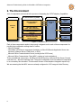
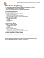
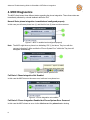
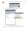
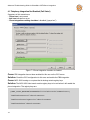
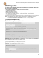
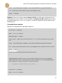
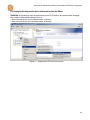
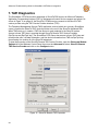
Advanced
Troubleshooting
Guide for
ShoreWare
CSTA Server
Version 1.0
While the information in this publication is believed to be accurate, ShoreTel makes no warranty of
any kind with regard to this material including, but not limited to, the implied warranties of
merchantability and fitness for a particular purpose. ShoreTel shall not be liable for errors contained
herein, or for incidental or consequential damages in connection with the furnishing, performance,
or use of this material. Information in this publication is subject to change without notice.
COPYRIGHT NOTICE
No part of this publication may be reproduced, stored in a retrieval system or transmitted, in any
form or by any means, photocopying, recording or otherwise, without prior written consent of
ShoreTel. No third party intellectual property right liability is assumed with respect to the use of the
information contained herein. ShoreTel assumes no responsibility for errors or omissions contained
in this book. This publication and all features described herein are subject to change without notice.
Copyright © 2008 by ilink Kommunikationssysteme GmbH. All rights reserved.
Copyright © 2008 by ShoreTel Inc. All rights reserved.
All products or services mentioned in this manual are covered by the trademarks, service marks, or
product names as designated by the companies who market those products.
ShoreTel, Inc
960 Stewart Dr.
Sunnyvale, CA 94085 USA
+1 (800) 425-9385 Toll Free
+1 (408) 331-3300 Tel
+1 (408) 331-3333 Fax
www.shoretel.com
October 2008..
Table of Contents
Introduction...................................................................................... 5
The Environment.............................................................................. 6
Troubleshooting Strategy ................................................................
7
Existing Phone Integration
7
Initial Phone Integration
7
Ruling Out User Error
7
MOC Diagnostics............................................................................. 8
Telephony Integration Not Enabled (Fail State I)
10
No Phone System Connection (Fail State II)
11
CSTA Diagnostics...........................................................................12
Diagnostic Session Facilities
12
CSTA Server Service(s) Not Running
13
Invalid Device Extension (Monitor)
14
Wrong Listener Port Configuration
14
Listener Port Already In Use by Another Process
15
Requests from the OCS Host are Blocked
15
License expired
16
Monitor Points Exceeded
16
Server Port Cascading Failure
17
Configuration Files
19
Translating Numbers Received from uaCSTA Clients............................... 21
Translating Numbers to be Delivered to uaCSTA Clients.......................... 22
3
Configuring Dialplan for On-Net Dialing..................................................... 22
Installer Parameters
23
OCS Diagnostics ............................................................................
25
No Matching Routing Table Rule
25
Host Authorization not Configured or Incorrect
25
Checkbox “Replace Tel-URI” Not Enabled
26
Invalid Device Identifier
27
Changing Routing and/or Host Authorization Has No Effect
29
TAPI Diagnostics............................................................................ 30
Logging........................................................................................... 33
OCS Logging
33
MOC Logging
36
CSTA Logging
39
Advanced Troubleshooting Guide for ShoreWare CSTA Server Integration
Advanced Troubleshooting Guide
for ShoreWare CSTA Server
Integration
1. Introduction
This document assumes familiarity with the documentation describing product installation and
configuration:
• ShoreWare CSTA Server Installation
• ShoreWare OCS 2007/OCS 2007R2 Telephony Integration / ShoreWare LCS 2005 Telephony Integration
Read these documents carefully as they provide enough information to find and fix the most
common issues. This document is intended to be used as an advanced troubleshooting guide for
administrators and support professionals with experience in troubleshooting Microsoft server
environments. It suggests strategies and techniques for resolving problems with deployments of
Shoretel CSTA Server with a specific focus on Microsoft MOC/OCS 2007/OCS 2007R2.
Since there is no significant difference between MOC/OCS 2007/OCS 2007R2 and the MOC/LCS
2005, the 2005 versions are not explicitly mentioned here.
The following terms and abbreviations are used in this document.
Term
OCS
MOC
CA
LinkTSP
AD
DVM
DVS
Definition
Microsoft Office Communications Server
Microsoft Office Communictor
Connectivity Adaptor
Link Tapi Service Provider
Active Directory
Distributed Voicemail Server, also known as ShoreWare Remote
Application Server
Distributed Voicemail Server, also known as ShoreWare Remote
Application Server
5
Advanced Troubleshooting Guide for ShoreWare CSTA Server Integration
2. The Environment
A lot of components are involved in the process of integrating the CSTA Telephony Capabilities.
HQ Server
Remote Server (e.g. DVM)
“ShoreTel-CSTAsvr”
CSTA Server
ShoreTel
PBX
OCS Server
Microsoft
OCS
User Client
Microsoft
Office
Communicator
User Client
“ShoreTel-CSTAcnr”
CSTA - TAPI Connectivity
“ShoreTel-CSTAlnk”
TAPI Link
TSPI
ShoreTel Telephony
Service Provider
Microsoft
Office
Communicator
User Client
Microsoft
Office
Communicator
Figure 1—Architecture
Each of these components needs to be properly configured and for each of these components it is
possible that configuration settings lead to a failure
• ShoreTel System
• ShoreWare CSTA Server components (installed on a ShoreTel Remote Application Server also
known as a Remote Server, DVM Server, or DVS)
• Microsoft Office Communications Server (running at the OCS Server)
• Microsoft Office Communicator Client (MOC, running on local workstations)
There are additional components - like Microsoft Active Directory or Microsoft SQL Server, Domain
controllers etc., which are implicitly used. The proper configuration for these additional components
is not covered by this document. This document focuses on the telephone Integration aspect only.
We are assuming that the MOC users are already configured for OCS usage in Active Directory.
6
Advanced Troubleshooting Guide for ShoreWare CSTA Server Integration
3. Troubleshooting Strategy
The approach for narrowing down a phone integration issue depends on the context:
• Initial Phone Integration (“first time”) – does not work
• Existing Phone integration environment (partially) stopped working
3.1.Existing Phone Integration
Choose a top down approach:
• Check MOC settings regarding “Phone enabled”
• Check OCS settings regarding
• Global settings like static routing, authorization
• User specific settings like telURI, Phone Integration enabled
• Check CSTA settings regarding
• General system availability
• Licensing
• Valid extension
3.2.Initial Phone Integration
Choose a bottom up approach
• Check CSTA settings regarding
• General system availability
• Licensing
• Valid extension
• Check OCS settings regarding
• Global settings like static routing, authorization
• User specific settings like telURI, Phone Integration enabled
• Check MOC settings regarding “Phone enabled”
3.3.Ruling Out User Error—Dialing Formats
Users may complain that they are unable to dial certain numbers. Before commencing
troubleshooting of the configuration, first confirm that the user is entering the numbers to be dialed
correctly and that numbers entered into directories and databases being used are correctly
formatted.
Numbers dialed by client applications such as Microsoft Office Communicator must be in a
canonicalized “international” format, for example, +14085551234.
7
Advanced Troubleshooting Guide for ShoreWare CSTA Server Integration
4. MOC Diagnostics
The MOC client knows three different states regarding the phone integration. These three states are
immediately reflected by a visual feedback within the GUI
Normal State: phone integration is enabled and configured properly
In this case you will see a phone icon (1) and the info icon (2) does not show an error.
Figure 2—MOC is enabled and configured properly
Note: The MOC might show a phone icon indicating “Ok” (1) but also a Tray Icon with the
contrary indication(2). After a while the “Phone System Error” within the Tray Icon will
disappear automatically.
Figure 3—Spurious phone system error
Fail State I: Phone Integration Not Enabled
In this case the MOC does not show an error, but there is no phone icon
Figure 4—Phone integration not enabled
Fail State II: Phone Integration Enabled but Phone System Error Occurred
In this case the MOC shows an error via the info icon and the phone icon is missing
8
Advanced Troubleshooting Guide for ShoreWare CSTA Server Integration
Figure 5—Phone integration is enabled but an error has occurred
More information about the error is displayed via the info icon.
Figure 6—Phone integration error notification
These two fail states (“Fail State I” and “Fail State II”) are discussed below in separate sections.
9
Advanced Troubleshooting Guide for ShoreWare CSTA Server Integration
4.1.Telephony Integration Not Enabled (Fail State I)
Symptoms of this scenario are:
• Phone icon is not present
• Info icon indicates no errors
• Phone Integration enabling checkbox is disabled (“grayed out”)
Figure 7—Phone Integration checkbox is disabled
Cause: PBX integration has not been enabled for this user on the OCS server
Solution: Check the OCS configuration for this user and enable the PBX integration
Cause: MOC 2005 running on a system that is missing certain registry keys
Solution: The MOC 2005 client needs certain registry keys to be set before it will enable the
phone integration. The registry keys are:
[HKEY_LOCAL_MACHINE\SOFTWARE\Policies\Microsoft\Communicator]
"EnablePhoneControl"=dword:00000001
"EnableConferencingService"=dword:00000001
"EnablePC2Phone"=dword:00000001
10
Advanced Troubleshooting Guide for ShoreWare CSTA Server Integration
4.2.No Phone System Connection (Fail State II)
Symptoms of this scenario are:
• Phone icon is not present
• Info icon indicates a failure (“No Phone System Connection”)
Cause: OCS Environment not properly configured
Solution: Check the configuration of the OCS server, the ShoreWare CSTA server, and the PBX..
If you are an Administrator then you could enable the MOC logging feature. Follow the instructions
below for CSTA diagnostics. If everything seems to be OK then move on to OCS diagnostics.
11
Advanced Troubleshooting Guide for ShoreWare CSTA Server Integration
5. CSTA Diagnostics
The ShoreWare CSTA Server consists of three subcomponents
• ShoreTel-CSTAsvr – the CSTA Server
• ShoreTel-CSTAcnr – Connectivity Adaptor
• ShoreTel-CSTAlnk – TAPI bridge
Figure 8—Windows Services Panel
Each of these software components runs as a distinct Microsoft Windows System Service so first
check to be sure that all of these services are up and running (this is explained below).
Note: The term “CSTA Server” generally refers to the top level component which is the
ShoreTel-CSTAsvr system service. The other two components (ShoreTel-CSTAcnr
and ShoreTel-CSTAlnk) do not expose “public capabilities” and are only used
internally by the ShoreTel-CSTAsvr component.
5.1.Diagnostic Session Facilities
The CSTA Server has two built-in diagnostics session facilities. Both of them are accessible using a
standard Telnet program such as the one included with the Microsoft Windows operating systems.
Note: In the examples of Telnet use in this manual the address of the server is specified as
the loopback address localhost to illustrate Telnet running on the same host as the
CSTA server. Telnet could be running on an computer with network access to the
CSTA server which would then be identified by its IP address.
Note: These examples also use the default value of the CSTA serverʼs port number which
is 26535. A different port number can be configured for the CSTA server by changing
the appropriate entry in the CSTA serverʼs Default.conf configuration file. (This is
described later in this manual.)
The SuperVisor Session
The SuperVisor session can be used to check licensing, PBX reach-ability, and version information.
telnet localhost 26535
SuperVisor BYE 12
(connects to the CSTA Server)
(login to a SuperVisor session)
(ends a SuperVisor sessions)
Advanced Troubleshooting Guide for ShoreWare CSTA Server Integration
The STLI Session
The STLI session can be used to check basic telephony features (e.g. device monitors).
telnet localhost 26535
STLI BYE (connects to the CSTA Server)
(login to a STLI session)
(ends an STLI sessions)
Note: The Telnet client has some restrictions:
• special keys do not work, e.g. if you have a type a command you cannot use the
backspace key for corrections. (Thatʼs because the backspace character will be part of the
command).
• There is no initial prompt. You have to start your diagnostic session by blindly typing the
appropriate command (STLI or SuperVisor)
5.2.CSTA Server Service(s) Not Running
The CSTA Server consists of three sub components which run as Windows System Services.
These three services must be up and running. Use the Microsoft Windows Services Panel or the
ShoreWare Director Quick Look Distributed Server Maintenance Page to check the status of these
services.
Figure 9— ShoreWare Director Quick Look Distributed Server Maintenance Page
13
Advanced Troubleshooting Guide for ShoreWare CSTA Server Integration
If these services must be manually restarted you should use the following sequence for start up:
1. ShoreTel-CSTAlnk
2. ShoreTel-CSTAcnr
3. ShoreTel-CSTAsvr
This sequence is recommended but not strictly required since all of these services have built-in
automatic synchronizing and recovery capabilities but the use of this sequence will decrease the
time which is needed to synchronize between these components and the availability of the whole
system is reached much faster.
5.3. Invalid Device Extension (Monitor)
Login via STLI session.
telnet localhost 26535
STLI (connects to the CSTA Server)
(login to a STLI session)
Assuming that you want to use the device 3000, than you could use the MonitorStart command,
MonitorStart 3000
(starts monitor on x3000)
If the MonitorStart command responds with an error indicating an invalidMonitorObject then
you are using an extension number that does not exist or is invalid:
error_ind UniversalFailure operationalError
invalidMonitorObject
In the example above, an attempt is made to start a monitor on extension 3000 but the
invalidMonitorObject reference in the response indicates that there is no extension 3000 that
can be monitored on the PBX.
5.4. Wrong Listener Port Configuration
Using Telnet on the DVM host (that is the computer where the CSTA Server is running) enter the
following (note that the characters SuperVisor that you type will not be echoed back on the
screen—youʼll be typing “blind”):
telnet localhost 26535
SuperVisor
error_ind SUCCESS SuperVisor
BYE
(connects to the CSTA Server)
(login to a SuperVisor session)
(response indicates success)
(disconnects from session)
If an error message such as connection refused or something similar appears, the port is
probably not 26535. Please check the configuration. The login port is configured during the
installation process and may be manually configured via the setting loginPort inside the
Default.conf configuration file.
14
Advanced Troubleshooting Guide for ShoreWare CSTA Server Integration
5.5.Listener Port Already In Use by Another Process
Using Telnet on the DVM host (that is the computer where the CSTA Server is running)
Type the following (again, the word SuperVisor that you type will not be echoed back on the
screen).
telnet localhost 26535
SuperVisor
If the response is neither connection refused nor error_ind SUCCESS SuperVisor then it
is very likely that another process is listening on 26535. To confirm this, shutdown the ShoreTel-svr
process and try this Telnet test again. If the same response is received, then you are sure that
another process is using port 26535.
Solution: Either shutdown the foreign process, or if this is not possible, choose a different listener
port for the CSTA server via the loginPort setting inside the Default.conf file and restart the
ShoreTel-svr process.
Note: We recommend that you use Netstat, a bult-in Microsoft Windows Networking tool
which is capable of showing the listeners and the the related program binaries:
C: netstat –a –b
This might help you to identify the foreign process which occupies the 26535 port. Be aware that
the netstat command runs extremely slowly in conjunction with the –b parameter.
5.6.Requests from the OCS Host are Blocked
Login to the OCS host (that is the computer where the OCS2007 Server is running). Lets assume
that the DVM host (that is where the CSTA Server is running) has the IP-Address 10.99.0.10.Type:
telnet 10.99.0.10 26535
SuperVisor
(Note that the word SuperVisor that you type will not be echoed back on the screen—youʼll be
typing “blind”.) The SuperVisor login command should respond with the message:
error_ind SUCCESS SuperVisor
If you are seeing a connection refused error message or something similar, it is very likely that there
is a network connectivity issue or a firewall preventing connections from the OCS host to the DVM
host for the specified port.
15
Advanced Troubleshooting Guide for ShoreWare CSTA Server Integration
Solution: Ping end to end, then verify with your network administrator that there arenʼt any
network rules or policies that prevent access. Change firewall rules to allow TCP connections from
the OCS host to the DVM host for the specified port.
5.7.License expired
Use the License command of a SuperVisor Telnet session to check the license.
This command responds with information about the installed license.
License
error_ind SUCCESS License
maxMonitors: 9
days left: 60
expired: no
If the license command indicates an expired license please contact your ShoreTel sales
representative to obtain a new license file. Install a valid license for the CSTA Server by copying
and pasting it into the CSTA Server Default.conf file or by using the License Tool application.
5.8.Monitor Points Exceeded
To check how many monitor points are actually in use, utilize the ShowDeviceMonitors
command after starting a SuperVisor session using Telnet. This command lists all the monitored
devices (each of them consuming a single license)
ShowDeviceMonitors
error_ind SUCCESS ShowDeviceMonitors
1000 sticky:false active:true observers:1
1001 sticky:false active:true observers:2
1002 sticky:false active:true observers:1
1003 sticky:false active:true observers:1
1004 sticky:false active:true observers:5
1005 sticky:false active:true observers:1
1006 sticky:false active:true observers:1
1007 sticky:false active:true observers:1
When a device is already monitored and another monitoring request for the same device is received
by the CSTA Server it does not consume a new license. The number of active monitors for a given
extension is indicated by the observers value. In this example there are 8 used monitors
(1000-1007, requiring at least 8 licenses) however there are a total of 13 active monitors because
there are 5 observers on extension 1004 and 2 observers on extension 1001.
16
Advanced Troubleshooting Guide for ShoreWare CSTA Server Integration
If you suspect that the number of monitored devices allowed by your license has been exceeded
you can directly attempt to start monitoring a device that is not yet being monitored using an STLI
session. For example:
telnet localhost 26535
STLI
error_ind SUCCESS STLI
MonitorStart 1000
If the MonitorStart command responds with an error that references LICENSEERROR
MONITORINGPOINTSEXCEEDED, it means that you do not have a license with permission for
enough monitored devices.
error_ind LICENSEERROR MONITORINGPOINTSEXCEEDED
Monitor not set
Solution: Obtain a new license file with a larger monitor limit. Replace the existing license with
the larger license by copying and pasting it into the CSTA Server Default.conf file or by using the
License Tool application.
5.9.Server Port Cascading Failure
ShoreWare CSTA server functionality is based on three separate subcomponents. These
components are cascaded together via TCP/IP sockets.
Usually you do not have to change any of these ports. The Installer chains up these ports correctly
using the default values as shown in Figure 10.
Figure 10 shows the keyword entries in the configuration files for each component and the default
values. Installations should reserve the default ports of 26000, 26001, and 26535 for the
ShoreWare CSTA Server. Only if it is essential that another process use one of the default ports,
should the default port settings in the configuration files be overridden.
17
Advanced Troubleshooting Guide for ShoreWare CSTA Server Integration
Remote Server (e.g. DVM)
OCS Server
DVM IP Address
loginPort=26535
TCP/IP
Microsoft OCS
“ShoreTel-CSTAsvr”
CSTA Server
cstaLinkPort=[server_port]
Routing IP =
[DVM IP Address]
Routing Port = [LoginPort]
Authorized IP = [DVM IP Address]
TCP/IP
server_port=26001
“ShoreTel-CSTAcnr”
CSTA - TAPI Connectivity
nettspi_port=[loginPort]
TCP/IP
loginPort=26000
“ShoreTel-CSTAlnk”
TAPI Link
TSPI
ShoreTel Telephony
Service Provider
Figure 10—Cascading TCP ports
18
Advanced Troubleshooting Guide for ShoreWare CSTA Server Integration
5.10.Configuration Files
By default, the configuration files for the CSTA Server components are stored in the directory
C:\Program Files\Shoreline Communications\ShoreWare Server\CSTA\Config
Note: You do not usually need to modify these files as these are already properly
configured by the CSTA Server Installer.
Note: As a best practice, you should always create a backup copy of a configuration file
before modifying it.
ShoreTel-CSTAsvr Settings
The configuration file for the ShoreTel-CSTAsvr is named Default.conf. It contains the following keys.
Key
Default
Comment
loginPort
26535
Listener Port.
This port is to be used in the OCS routing
settings
Default is empty: demo mode with 1 monitor,
license
logFileMaxSize
100
logFileMaxBackups
2
debugLevel
0
cstaLogEnabled
interfaceLogEnabled
cstaLinkAddress
cstaLinkPort
9 = for logging during debug sessions
0
Write csta.log (0 or 1)
0
Write Interface.log (0 or 1)
127.0.0.1 The ip address for the host where ShoreTelCSTAcnr service is running. By default this is the
loopback address because it is on the same
host as the ShoreTel-CSTAsvr service.
26001
The listener port of the ShoreTel-CSTAcnr.
Note: this port is explicitly set to 26001 during
the installation
List of prefixes used if ShoreTel On-Net Dialing
feature is activated. All prefixes are listed on a
single line separated by semicolons (“;”) By
default this is empty.
onNetPrefixList
maxExtensionLength
Otherwise: a hexdump on a single line with
encrypted licensing data
Maximum size of a log file In KByte units. Actual
size is limited only be file system constraints.
The recommended range is 10 to 2000.
Number of log files to keep during log rotation.
Actual number is limited only be file system
constraints. The recommended range is 0 to 30.
0 = debug logging switched off
5
Note: Configuring the CSTA server for On-Net
Dialing also requires making corresponding
entries in the Dialplan.conf file (see below).
Maximum number of digits in an extension
number. Should be set to 3, 4, or 5.
19
Advanced Troubleshooting Guide for ShoreWare CSTA Server Integration
rfc2806PrivateContext
setsignalhandler
1
“Private Context” string used to construct
RFC2806 telURIs for extension numbers that
have no corresponding DID number. The DID
Prefix entered during installation is unique to the
PBX and is used for this purpose.
For debugging only in the case a crash occurs:
0 : donʼt create a coredump
1 : create a coredump
ShoreTel-CSTAcnr Settings
The configuration file for the ShoreTel-CSTAcnr is named ca_config.properties. It contains the
following keys.
Key
Default
Comment
server_port
26001
The listener port.
nettspi_hostname 127.0.0.1 The ip address for the host where the ShoreTelCSTAlnk service is running. By default this is the
loopback address because it is on the same host as
the ShoreTel-CSTAcnr service.
nettspi_port
20000
The port of the ShoreTel-CSTAlnk service.
ShoreTel-CSTAlnk Settings
The configuration file for the ShoreTel-CSTAlnk is named LINKTSP.INI. It contains the following
keys.
Key
Default
Comment
loginPort
20000
The listener port.
Driver
RpcTspX.tsp The TAPI TSP driver DLL
ShoreTel-CSTAcnr and ShoreTel-CSTAlnk Logging Settings
The ShoreTel-CSTAcnr and ShoreTel-CSTAlnk share a common configuration file that controls
logging behavior named log4j-config.xml. This is an XML file that contains additional key value pairs
using XML tags. The key “level value” appears once for each component. To change the level of
detail in the log files produced, change the value for these keys.
Key
Default
Comment
level value
ERROR
Logging level. The default, “ERROR”, will log only
errors. To capture all debugging information, change
this value to “DEBUG”. To stop all logging change
the value to “OFF”.
20
Advanced Troubleshooting Guide for ShoreWare CSTA Server Integration
Dial Plan Settings for uaCSTA Clients
The ShoreWare CSTA Server provides a telephone number mapping function for clients using the
uaCSTA protocol such as Microsoft OCS software. Mapping, or translation, of telephone numbers is
controlled by the DialPlan.conf configuration file. (The Default.conf file provides extension length and
On-Net Dialing prefix values.) DialPlan.conf contains two tables each with two columns of values.
The first columns of both tables start in the first character position and the second columns start
after a run of tabs and/or spaces.
The first table is known as the “Extension Translation Table” and it starts after a line that reads:
--Extension Translation Table
The entries in this table tell the gateway how to map references to internal extensions between DID
numbers and extension numbers that can be dialed by the PBX. The first column contains
characters to match with an external number (including country code). The second column contains
digits to substitute in order to form the corresponding extension number.
The second table is known as the “External Translation Table” and it starts after a line that reads:
--External Translation Table
The entries in this table tell the gateway how to map references to external numbers between DID
numbers and digit sequences that can be dialed by the PBX. The first column contains characters
to match with an external number (including country code). The second column contains digits to
substitute in order to form the corresponding dialable sequence.
Note: All entries are evaluated in the order they appear in the DialPlan.conf file. For
translation to occur correctly, make sure that every entry is in the correct order: from
most specific to least specific.
Translating Numbers Received from uaCSTA Clients
Telephone numbers received from a uaCSTA client are first examined to determine if they are
already dialable extension numbers (based on their length) or On-Net Dialing extensions (based on
their prefix). If so, no translation is required.
Otherwise, these numbers are processed by matching the leading characters of the telephone
number provided with an entry in the first column of the Extension Translation Table. If a match is
found, the matching portion of the provided telephone number is replaced with the digits found in
the corresponding entry in the second column.
The examples below illustrate the substitution process for mapping to extension numbers:
First Column
+14085551
+14085551
+140828512
+14085551234
Second Column
11
589
7
456
Number Provided
+14085551234
+14085551234
+14085551234
+14085551234
Resulting Extension
11234
589234
734
456
21
Advanced Troubleshooting Guide for ShoreWare CSTA Server Integration
If no match is found in the Extension Translation Table, then the matching process is repeated using
the External Translation Table. The leading characters of the provided telephone number are
matched with an entry in the first column of the External Translation Table. If a match is found the
matching portion of the provided telephone number is replaced with the digits found in the
corresponding entry in the second column.
These examples illustrate the substitution process for mapping to a dialing sequence for an external
number:
First Column
Second Column Number Provided
Resulting External
Dialing Sequence
+
9+
+14085551234
9+14085551234
+1
91
+14085551234
914085551234
+1408
9
+14085551234
95551234
+1212
81212
+12125551234
812125551234
Translating Numbers to be Delivered to uaCSTA Clients
Telephone numbers received from the PBX are first examined to determine if they are extension
numbers (based on their length) or On-Net Dialing extensions (based on their prefix). If so, numbers
are converted from extension numbers to numbers in “international format” by matching the leading
digits of the extension number with an entry in the second column of the Extension Translation
Table. If a match is found the matching portion of the extension number is replaced with the digits
found in the corresponding entry in the first column. If no match is found no translation is performed.
If all the digits in the second column match the number in question, then all the digits are replaced
with the entry found in the corresponding first column.
These examples illustrate the substitution process:
First Column
+14085551
+14085551
+140828512
+14085551234
Second Column
11
589
7
456
Extension Number
11987
589123
789
456
Resulting Number
+14085551987
+14085551123
+14082851289
+14085551234
Telephone numbers received from the PBX that correspond to external numbers are converted to
DID numbers by matching the leading digits of the external number with an entry in the second
column of the External Translation Table. If a match is found the matching portion of the number is
replaced with the digits found in the corresponding entry in the first column. If no match is found
then no translation is performed. If all the digits in the second column match the external number,
then all the digits are replaced with the entry found in the corresponding first column.
These examples illustrate the substitution process:
First Column
+1
+1
Second Column
1
External Number
14085551987
4085551987
Resulting Number
+14085551987
+14085551987
Configuring Dialplan for On-Net Dialing
If the On-Net Dialing feature is enabled additional entries in the Extension Translation Table. As
described above, the CSTA Server determines if a number is an extension number or an external
22
Advanced Troubleshooting Guide for ShoreWare CSTA Server Integration
number based on its length. Telephone numbers too long to be extension numbers are considered
external numbers unless they start with one of the On-Net Dialing prefixes configured in the
Default.conf configuration file (see above).
If On-Net Dialing is configured then the extension numbers used in the mapping process will consist
of the On-Net Dialing prefix followed by an extension number of the standard length and the
Extension Translation Table must contain appropriate entries.
For example, a PBX is configured to use 3 digit extensions and an On-Net Dialing prefix of 589. All
extensions associated with that prefix are associated with the DID range (408)555-1xxx. In this
case the On-Net Dialing prefix 589 would be added to the list of On-Net Dialing prefixes configured
in the Default.conf file and there would be an entry in the Extension Translation Table of the
Dialplan.conf fie with +14085551 in the first column and 589 in the second column. This example
is also illustrated in the second rows of each of the two sets of Extension Translation Table
examples above.
5.11.Installer Parameters
During installation of the CSTA Server the installer requests two parameters: a Trunk Access Code
and a DID Prefix. These parameters are used by the installer when it generates an initial
DialPlan.conf file and create default entries in both the Extension Translation Table and the External
Translation Table.
The DID Prefix consists of the unique digits, including the country code and the first digit of the
extension range, that define a DID range in the PSTN. For example, if the DID range is
+1(408)555-7000 through +1(408)555-7999 it means that the carrier has allocated all PSTN
numbers starting with the digit sequence 14085557 to the PBX in question.
The DID prefix that is requested is also mapped internally to the following configurations key and
stored into the Default.conf file.
Parameter Label Internal Parameter Name
Comment
DID Prefix
rfc2806PrivateContext
MOC 2007 requires that extensions that
cannot be mapped to any number in the
PSTN must be specially encoded when
placed in the uaCSTA protocol. This
encoding is specified in RFC2806 which
requires a “Private Context” string which
uniquely identifies the PBX. The DID prefix
for the PBX satisfies this requirement and is
used for this purpose by default.
In a typical configuration the PBX with the DID prefix 14085557 would have these DID numbers
assigned to extensions 7000 through 7999 respectively. The installer supports this basic
configuration by creating a single entry in the DialPlan.conf file that maps PSTN number
+1(408)555-7xxx to extension 7xxx. The entry in the Extension Translation Table in DialPlan.conf for
this example is:
+14085557
7
This entry tells the CSTA Server to map to internal extension numbers by replacing the leading
digits “+14085557” with just the digit “7” and to convert from internal extension numbers by
replacing the leading digit “7” with the digits “+14085557”.
23
Advanced Troubleshooting Guide for ShoreWare CSTA Server Integration
Note: The installer only asks for a single DID Prefix so the one entered should be the
primary DID prefix associated with the PBX. Additional DID range mappings must be
added to the DialPlan.conf file manually. The installer assumes that the PBX
conforms to the convention that all extensions corresponding to the DID range start
with the last digit of the ID Prefix. If this is not the case, the DialPlan.conf file must be
manually corrected after the installation process is completed. ShoreTel Professional
Services may be engaged to assist with this process.
The installer uses the trunk access code parameter to create a default entry in the External
Translation Table for converting canonical numbers to a digit sequence that can be dialed. It does
this by creating an entry that prefixes canonical numbers with the trunk access code.
For example, if the trunk access code entered was “9” then the entry created in the External
Translation Table in DialPlan.conf would be as follows:
+
9+
Note: The installer does not create default entries in the External Translation Table for
mapping external numbers. In the basic configuration external numbers are delivered
to the uaCSTA client as they are received from the PBX. If mapping of these
numbers is required, appropriate entries must be created in the DialPlan.conf
External Translation Table.
The example below illustrates the importance of entering the correct DID Prefix. In this case a user
has extension 1100 and their OCS telURI setting is +14085551100.
DID Prefix
Resulting extension
comment
+14085551
1100
ok
+1408555
51100
wrong
+140828511
100
wrong
+4930828526
+14085551100
wrong
Troubleshooting DialPlan.conf
To confirm an issue with the DialPlan.conf file
1. Prepare a list of valid extensions and their corresponding telURIs as entered into OCS settings
2. Open the DialPlan.conf file with a text editor
3. For each telURI, scan the first column in DialPlan.conf and find the first entry that matches the
leading digits of the telURI then replace the matching digits with the digits in the second column
and match the result against the correct extension.
4. For each telURI, scan the second column in DialPlan.conf and find the first entry that matches
the leading digits of the extension then replace the matching digits with the digits in the first
column and match the result against the correct telURI.
If any converted number doesnʼt match, confirm that the telURI entered into OCS was valid. If so,
the DialPlan.conf file is the source of the problem.
Solution: Manually correct the DialPlan.conf file by reordering or correcting existing entries,
deleting invalid entries and/or adding missing entries then restart the CSTA server components.
24
Advanced Troubleshooting Guide for ShoreWare CSTA Server Integration
6. OCS Diagnostics
The majority of phone integration failures result from mistakes in OCS configuration. Always begin
with a simple check of the following:
• Host Routing and authorization settings (which are global settings)
• Ip address and port correct ?
• Replace URI checkbox enabled ?
• Matching routing table rule correct ?
• User specific phone settings (which are – as the name implies – personal settings)
• Is the telURI entered correctly ?
If this check does not lead to a solution than the usage of the OCS logging tool is to be considered.
Note: OCS logging has to be explicitly enabled. The examples in this illustration all refer to
an OCS log file generated as documented in Section 8.1 OCS Logging, below.
6.1.No Matching Routing Table Rule
Symptom: The message flow in the logfile is similar to:
Text: Non-trusted source sent an FQDN/IP that doesn't match a
routing table rule
Result-Code: 0xc3e93c5e SIPPROXY_E_ROUTING
SIP-Start-Line: INVITE sip:[email protected]
SIP/2.0
SIP-Call-ID: 19c4aacda45340a3b58eb9d602b2c073
SIP-CSeq: 1 INVITE
Data: user="[email protected]"
Solution: Change the static routing rule or change the SIP URI for the user (in this example there
was no routing rule for dvm1.csta.yourcompany.com).
6.2.Host Authorization not Configured or Incorrect
Symptom: The message flow in the logfile is similar to:
Direction: incoming
Peer: 10.0.10.5:26535
// this is the ip:port of the CSTA server
Message-Type: response
Start-Line: SIP/2.0 200 OK
25
Advanced Troubleshooting Guide for ShoreWare CSTA Server Integration
From: <sip:[email protected]>;tag=f2bbc17a0c;epid=0d60acc870
To: <sip:[email protected]>;tag=228669937.656000
CSeq: 1 INVITE
Call-ID: 39413069451248c484e113bf7ecf11d6
Via: SIP/2.0/TCP
[…] … a lot of messages are shown here before … […]
LogType: diagnostic
Severity: warning
Text: Message was discarded by the application
Result-Code: 0xc3e93ec6 SIP_E_AUTH_CANNOT_CHALLENGE
SIP-Start-Line: SIP/2.0 200 OK
SIP-Call-ID: 39413069451248c484e113bf7ecf11d6
SIP-CSeq: 1 INVITE
Data: application="http://www.microsoft.com/LCS/UserServices"
$$end_record
Solution: Set the IP address of the CSTA Server host as trusted via the host authorization rules.
(In this example there was a matching routing rule, but the host 10.0.10.5 was not added to the list
of authorized hosts.)
6.3.Checkbox “Replace Tel-URI” Not Enabled
Symptom: The message flow in the log file is similar to:
Direction: outgoing
Peer: 10.0.10.5:26535
Message-Type: request
Start-Line: INVITE sip:[email protected] SIP/2.0
26
Advanced Troubleshooting Guide for ShoreWare CSTA Server Integration
From: <sip:[email protected]>;tag=b5b968571c;epid=0d60acc870
To: <sip:[email protected]>
CSeq: 1 INVITE
Solution: Check the checkbox labeled Replace Tel-URI in the OCS static routing rules for the
CSTA Gateway server in question. (In this example, the Replace Tel-URI checkbox was not set so
the symbolic name dvm1.csta.yourcompany.com was not replaced by the IP-address of the
receiving host.)
6.4.Invalid Device Identifier
Symptom: the message flow in the logfile is similar to:
Direction: outgoing
Peer: 10.0.10.5:26535
Message-Type: request
Start-Line: INFO sip:[email protected]:26535;transport=tcp SIP/
2.0
From: <sip:[email protected]>;tag=23e5b8a60a;epid=0d60acc870
To: <sip:[email protected]>;tag=228744379.126000
CSeq: 3 INFO
Call-ID: ddf44c3ae51d49989c7ff897041512c6
…
<MonitorStart xmlns="http://www.ecma-international.org/standards/
ecma-323/csta/ed3"><monitorObject><deviceObject>tel:+4930282561000</
deviceObject></monitorObject></MonitorStart>
[ … stripped of some message noise here … ]
Direction: incoming
Peer: 10.0.10.5:26535
27
Advanced Troubleshooting Guide for ShoreWare CSTA Server Integration
Message-Type: response
Start-Line: SIP/2.0 200 OK
From: <sip:[email protected]>;tag=23e5b8a60a;epid=0d60acc870
To: <sip:[email protected]>;tag=228744379.126000
CSeq: 3 INFO
Call-ID: ddf44c3ae51d49989c7ff897041512c6
…
Message-Body: <?xml version="1.0" encoding="UTF-8"?
><CSTAErrorCode><operation>invalidDeviceID</operation></
CSTAErrorCode>
The problem illustrated in this example was caused when the phone number configured for a given
users doesnʼt match the phone numbers available on the PBX.
Solution: First verify that all the entries for all DID ranges appear in the DialPlan.conf file, that all
entries are correct, and that all entries are in the correct order. If the DialPlan.conf file is valid, the
problem lies with the Line URI entered into a userʼs configuration. Itʼs common to find typographical
errors such as entering +14085552561 instead of +14085555261.
Canonicalized “international” format numbers (i.e. +14085551234) are required for user telephone
number entries used in conjunction with OCS.
In the case that an incorrect telephone number entry was made in Active Directory and then
corrected, the data in Active Directory must be resynchronized with OCS. An Address book sync up
can be forced by using the following command from \program files\microsoft office communications
server 2007\server\core: Run abserver -syncnow.You will see an entry in the event log indicating
that the import has completed. Microsoft Office Communicator will download the new phone
number for the user in question when it is restarted.
28
Advanced Troubleshooting Guide for ShoreWare CSTA Server Integration
6.5.Changing Routing and/or Host Authorization Has No Effect
Solution: At a minimum, the front end service of the OCS needs to be restarted after changing
the routing or authorization settings:To do so
• Stop front end service (via contextual menu, as shown)
• Start front end service (via contextual menu, as shown)
Figure 11—Stopping the OCS front end service
29
Advanced Troubleshooting Guide for ShoreWare CSTA Server Integration
7. TAPI Diagnostics
The ShoreWare CSTA Server takes advantage of ShoreTel PBX support for Microsoft Telephony
Application Programming Interface (TAPI) to exchange call control service requests and events. As
shown in Figure 10 on page 18, the ShoreTel-CSTAlnk service connects to the ShoreTel TAPI
service provider using the TAPI Service Provider Interface (TSPI).
The Telephony Management Service (TMS) application service (which runs on every ShoreWare
server) connects the ShoreTel TAPI service provider to the rest of the ShoreTel distributed PBX.
When TMS starts up, it creates a TAPI line device for each endpoint in the ShoreTel system.
Access to these TAPI lines is provided through ShoreTel Remote TAPI Service Providers
(RpcTsp.tsp and RpcTspX.tsp). The ShoreWare CSTA Server has access to these TAPI lines and
receives new calls, call state information, and line device information from TMS via RpcTspX.tsp,
thus allowing it to monitor all of the ShoreTel extensions.
To view the properties of the ShoreTel Remote TAPI Service Provider, open the Phone and Modem
Options tab in the Windows Control Panel, then from the Advanced tab select ShoreTel Remote
TAPI Service Provider and click on the Configure button.
Figure 12—ShoreTel Remote TSP Properties
30
Advanced Troubleshooting Guide for ShoreWare CSTA Server Integration
On a properly installed ShoreWare Remote Server (aka application server, DVS, DVM) the
ShoreTel Remote TAPI Service Provider status should appear as shown in Figure 12. The
Application Server and Server parameters are grayed out. The Login will be ShoreTel and no
other parameters are defined. The Provider Status will display the serverʼs localhost IP address,
verify that this is the correct IP address. In addition, verify that the Devices status shows the
appropriate number of lines and phones and that the Provider Usage is set to enable.
Several diagnostic steps involve observing the exchange of instructions and events between the
PBX and the system running the Shoreware CSTA Server through this TAPI service provider.
Diagnostics are done on the same host where the CSTA Server is running (the ShoreWare Remote
Server).
Use Microsoftʼs Dialer.exe application (usually installed by default on the Windows 2003 server), to
place a test call using one of the ShoreTel extensions. If it has never been used before the first step
is to configure a TAPI line, see Figure 13 below.
Figure 13—Configuring Dialer.exe
The Line is the name of a ShoreTel extension, along with the ShoreGear switch that is managing it
and port number. The Address is the actual extension number. Select an appropriate Line and
click on “OK”. If the dialer application was utilized before and the Connect Using window is not
displayed select Tools then Connect Using….
Note: If you cannot select the desired Line Address then there is probably something
wrong with the ShoreTel system, TAPI, or a communication problem. Please refer to
the appropriate ShoreTel Maintenance Guide or contact your service provider or
ShoreTelʼs Technical Assistance Center.
Once you have configured the appropriate line, the Phone Dialer application will be active, see
Figure 14 below
31
Advanced Troubleshooting Guide for ShoreWare CSTA Server Integration
Figure 14—Phone Dialer window
To test dialing functionality:
1. To place a call to another extension enter a valid extension in the Number to dial field
2. Press the Dial button
Note: If you wish to place a call to an external number you must use an appropriate trunk
access code followed by the full number (including country code). You cannot use a
a number like “+14085551212” here.
Note: If the TAPI phone dialer does not respond to the Dial command or shows an error
then there is probably something wrong with the ShoreTel system, TAPI, or a
communication problem. Please refer to the appropriate ShoreTel Maintenance
Guide or contact your service provider or ShoreTelʼs Technical Assistance Center.
Figure 15—Dialing window
3. Press the Hangup button to end the call.
4. Close the Phone Dialer application by closing the application window or by selecting Exit from
the File menu.
32
Advanced Troubleshooting Guide for ShoreWare CSTA Server Integration
8. Logging
8.1.OCS Logging
The OCS logging facility has to be explicitly enabled using the OCS Logging Tool.
Use the panel tree on the left to navigate to the OCS domain node (DO NOT select the OCS host
node). Right click on the OCS domain node to access the contextual menu and the select the
Logging Tool > New Debug Session option.
Figure 16—Starting a debug session
33
Advanced Troubleshooting Guide for ShoreWare CSTA Server Integration
Figure 17—OCS 2007/OCS 2007R2 logging tool window
Inside the Logging Tool window the following components must be checked in order to
troubleshoot OCS 2007/OCS 2007R2 telephony integration:
• Inbound Routing
• Outbound Routing
• SIPStack
The logging has to be explicitly started using the Start Logging button.
Note: The Start Logging button changes to a Stop Logging button when pressed.
After OCS logging has been started, sign-out/sign-in using the MOC client where the issue appears.
Reproduce the failing scenario and then click the Stop Logging button.
The Log File Folder C:\Windows\Tracing\ contains the log files in a binary format with filename suffix
“.etl”.
To view the contents of these logs, click the View Log Files button in the Logging Tool window.
The View Log Files window will then appear.
34
Advanced Troubleshooting Guide for ShoreWare CSTA Server Integration
Figure 18—View Log Files window
Indicate which logging information is to be viewed using the checkboxes, specify the filename for
the log to be read, and click the View button(1). This will convert the binary .etl files into a text file.
35
Advanced Troubleshooting Guide for ShoreWare CSTA Server Integration
8.2.MOC Logging
MOC logging needs to be explicitly enabled as follows:
1. Open the Options window.
Figure 19—Turning on logging in MOC options
2. Select the General tab.
3. Check the Turn on logging in Communicator checkbox.
4. Re-login to the MOC.
A logfile is produced now. This logfile is stored as C:\Documents and Settings\Administrator\Tracing
\Communicator-uccp-0.uccplog.
36
Advanced Troubleshooting Guide for ShoreWare CSTA Server Integration
Example content of the uucplog file:
04/01/2008|13:55:14.156 2BC:940 INFO
:: SIP/2.0 504 Server time-out
Authentication-Info: Kerberos
rspauth="602306092A864886F71201020201011100FFFFFFFF6D7B7A0E04D10F53B
A62891944F98297", srand="BB548579", snum="10", opaque="0FDE32B5",
qop="auth", targetname="sip/ocs.yourcompany.com", realm="SIP
Communications Service"
From: <sip:[email protected]>;tag=f94e507772;epid=0d60acc870
To:
<sip:[email protected]>;tag=399A3A01D09653F93535
7E3180DFD0EB
Call-ID: 82fbde0b79474e5a9b6f09414d333191
CSeq: 1 INVITE
[…]
The above example illustrates a scenario where the remote CSTA server cannot be reached for one
of the following reasons:
• Wrong static routing rules inside the OCS
• Network connectivity or firewall problem between OCS host and CSTA host
• CSTA Server is not up and running
• CSTA Server is configured with a wrong port number
Another example:
SIP/2.0
Via: SIP/2.0/TLS 192.168.46.10:2315
Max-Forwards: 70
From: <sip:[email protected]>;tag=ec0ca1c90f;epid=0d60acc870
To: <sip:[email protected]>;tag=228743379.844000
Call-ID: fdfd70fb2d7c4ec59e54c3bfde210eef
CSeq: 3 INFO
37
Advanced Troubleshooting Guide for ShoreWare CSTA Server Integration
Route: <sip:[email protected]:26535;transport=tcp>
User-Agent: UCCP/2.0.6362.0 OC/2.0.6362.0 (Microsoft Office
Communicator)
Content-Disposition: signal;handling=required
Supported: timer
Proxy-Authorization: Kerberos qop="auth", realm="SIP Communications
Service", opaque="78BC6FFF", crand="2cc70834", cnum="10",
targetname="sip/ocs.yourcompany.com",
response="602306092a864886f71201020201011100ffffffff649328f1d401309f
3f2b43df34d2b241"
Content-Type: application/csta+xml
Content-Length: 203
<?xml version="1.0"?>
<MonitorStart xmlns="http://www.ecma-international.org/standards/
ecma-323/csta/ed3"><monitorObject><deviceObject>tel:
+49302852610001</deviceObject></monitorObject></MonitorStart>
[… more messages follow …]
SIP/2.0 200 OK
Authentication-Info: Kerberos
rspauth="602306092A864886F71201020201011100FFFFFFFF8776FF604DE1F1019
71163A976FAFB2F", srand="2D061025", snum="12", opaque="78BC6FFF",
qop="auth", targetname="sip/ocs.yourcompany.com", realm="SIP
Communications Service"
Via: SIP/2.0/TLS 192.168.46.10:2315;ms-received-port=2315;msreceived-cid=400
From: <sip:[email protected]>;tag=ec0ca1c90f;epid=0d60acc870
To: <sip:[email protected]>;tag=228743379.844000
Call-ID: fdfd70fb2d7c4ec59e54c3bfde210eef
CSeq: 3 INFO
Contact: <sip:[email protected]:26535;transport=tcp>
38
Advanced Troubleshooting Guide for ShoreWare CSTA Server Integration
Content-Disposition: signal;handling=required
Content-Type: application/csta+xml
Content-Length: 107
<?xml version="1.0" encoding="UTF-8"?
><CSTAErrorCode><operation>invalidDeviceID</operation></
CSTAErrorCode>
In this example the MOC sent a Monitor Start Request which indicates that there is no
problem with routing, authorization, network connectivity, firewalls, etc.
The CSTA Server responds with a CSTAErrorCode of type invalidDeviceId to the
MonitorStart request. This indicates that the wrong Line URI was specified in the OCS user
specific phone settings.
Note: The Call-ID and the CSeq fields are very useful for tracing the flow of the SIP
messages within other logfiles (e.g. from the OCS 2007/OCS 2007R2 server)
because these attributes are used to correlate requests and responses.
8.3.CSTA Logging
The logfiles of the CSTA server are used primarily by ShoreTel to narrow down internal CSTA server
issues.
However, ShoreTel might request that CSTA server logging be enabled to help diagnose a problem.
Logging is enabled and configured via the CSTA serverʼs configuration file Default.conf which in turn
is normally located in the directory C:\Program Files\Shoreline Communications\ShoreWare Server\CSTA
\Config. This file is contains key/value pairs. The keys that control logging are as follows (default
values are specified)
cstaLogEnabled = 0
interfaceLogEnabled = 0 debugLevel = 0
# 0 -> off, 1 -> on
# 0 -> off, 1 -> on
# 0 -> off, 9 -> max
By default, the logfiles generated by the CSTA Server are found in the subdirectory C:\Program Files
\Shoreline Communications\ShoreWare Server\CSTA\logs\.
Filename
Component
Content
Format
Sys.log
ShoreTel-CSTAsvr Startup/Shutdown/licensing
Error.log
ShoreTel-CSTAsvr Internal processing
CSTA.log
ShoreTel-CSTAsvr Messages exchanged between ShoreTelhexdump
CSTAsvr and ShoreTel-CSTAcnr
Interface.log ShoreTel-CSTAsvr Incoming Messages and outgoing messages hexdump
correlated to the used protocol interfaces
CSTAcnr.log ShoreTel-CSTAcnr Internal processing
LinkTSP.log ShoreTel-CSTAlnk Internal processing
39