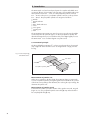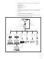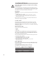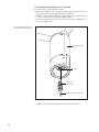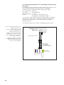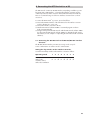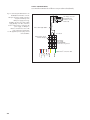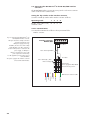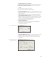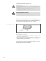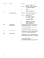
1
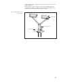
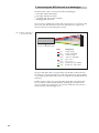
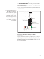
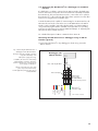
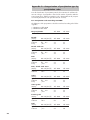
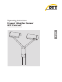
English
Operating instructions
Present Weather Sensor
OTT Parsivel 2
We reserve the right to make technical changes and improvements without notice.
Table of contents
1 Scope of delivery
5
2 Order numbers
5
3 OTT Parsivel2 factory settings
6
4 Safety instructions
7
5 Introduction
8
5.1 Functional principle
5.2 Connection options for the OTT Parsivel2
10
6 Installing the OTT Parsivel2
6.1 Cable selection
6.2 Connecting ground to OTT Parsivel2
6.3 Installing the OTT Parsivel2 on a pedestal
7 Connecting the OTT Parsivel2 to a datalogger
7.1 Connecting the OTT Parsivel to an OTT netDL IP datalogger using an RS-485 interface
7.2 Connecting the OTT Parsivel2 to a datalogger using an SDI-12 interface
7.3 Connecting the OTT Parsivel2 to a datalogger with pulse input
2
8 Connecting the OTT Parsivel2 to a PC
8.1
8.2
8.3
8.4
8.5
Connecting
Connecting
Connecting
Connecting
Connecting
the
the
the
the
the
OTT
OTT
OTT
OTT
OTT
Parsivel2
Parsivel2
Parsivel2
Parsivel2
Parsivel2
8
9
to
to
to
to
to
the RS-485/RS-232 interface converter
the ADAM-4520 RS-485/RS-232 interface converter
the RS-485/USB interface converter
any interface converter
a PC for configuring using a USB interface
9 Connecting the OTT Parsivel2 to a power supply
10
11
12
14
15
17
20
21
21
23
24
25
25
27
10 Heating the OTT Parsivel2 sensor heads
29
11 Operating the OTT Parsivel2 with a terminal software
30
11.1
11.2
11.3
11.4
11.5
Setting up communications between the OTT Parsivel2 and the terminal program
Measurement numbers
Defining the formating string
OTT telegram
Updating OTT Parsivel2 firmware
12 Maintenance
30
31
32
32
33
35
12.1 Cleaning the laser's protective glass
12.2 Keeping the light pathway open
12.3 Cleaning the splash protection unit
35
35
36
13 Functional disruptions and remedies
37
13.1 OTT Parsivel does not start
13.2 Disruptions due to convection and vibrations
2
37
37
14 Note about the disposal of old units
37
15 Technical data
38
3
Appendix A – CS command set
39
Appendix B – SDI-12 commands and responses
42
B.1 Basic commands
B.2 Advanced SDI-12 commands
Appendix C – Classification of precipitation types
C.1 Class limits
Appendix D – Categorization of precipitation type by precipitation codes
D.1 SYNOP precipitation code
D.2 NWS and METAR/SPECI w’w’ precipitation code, Table 4678
Appendix E – Declaration of conformity
4
42
45
46
46
48
48
49
50
1 Scope of supply
䊳 OTT Parsivel2
– 1 laser-optical disdrometer consisting of: two sensor heads with splash protection unit grid, tunnel housing with 30 mm wide and 180 mm long light strip,
base holder with integrated electronics and 8-pin panel jack for connecting
the supply voltage and electrical ports
– 1 installation set, consisting of
1 x cable lug for grounding
1 x flat washer
6 x grub screws M 8 x 16 mm
7 x grub screws M 8 x 25 mm
1 x hex nut M 8
2 x lock washers
1 x Allen key, 4 mm
– 1 USB connection cable. USB connector type A to USB type B, 3 m
– 1 OTT Parsivel PC software "ASDO", basic version
– 1 set of operating instructions
2 Order numbers
䊳 OTT Parsivel2
Laser-optical disdrometer
70.210.001.3.0
䊳 Accessories
Connection cable, assembled
– 8-core, wire cross section 0.25/0.75 mm2
– one end prepared with plug
– one open cable end, insulation removed and
provided with end sleeves
– Length 1 m, 13 m (available on request according
to customer requirements)
70.210.409.4.1
Power supply 24 V DC/100 W;
control cabinet version
– Protection class IP 20
– for top hat rail installation (TS 35)
– Input voltage: 100 … 240 V AC
65.030.003.9.2
Power supply 24 V DC/100 W;
protective housing version
– Protection class IP 65
– in aluminum protective housing
– Input voltage: 100 … 240 V AC
97.850.029.9.5
Interface converter
– RS-485 / USB; galvanically isolated;
electrical supply via USB interface
– RS-485 / RS-232; galvanically isolated;
external electrical supply 12 … 24 V required
Pedestal 2"
– with bottom plate for attachment to a concrete base
– with mounting plate for mains adapter
(protective housing version)
– Laser strip installation height: 1 m (length: 0.53 m)
– Laser strip installation height: 2 m (length: 1.53 m)
– Laser strip installation height: 3 m (length: 2.53 m)
䊳 Spare parts
97.961.091.9.5
97.970.041.9.5
70.210.420.3.1
70.210.421.3.1
70.210.422.3.1
Attachment set for pedestal
– for attachment of the pedestal on a concrete base
– 4 x anchor rods
– 4 x anchor bolt glue cartridges
99.020.050.9.2
OTT Parsivel PC software "ASDO", full version
56.551.001.9.7
Splash protection unit grid (1 piece)
70.210.410.3.1
5
3 OTT Parsivel2 factory settings
The OTT Parsivel2 is a flexibly configurable device with respect to interface activation and parameters and the heating setting, and is supplied with the following
factory settings:
Operating mode:
Baudrate RS-485:
RS-485 bus mode:
Bus address RS-485:
SDI-12 interface:
SDI-12 bus address:
Pulse output:
Heating mode:
Data telegram:
Measurement interval:
RS-485 2-wire *
19,200 baud
disabled
0
disabled
0
0.1 mm enabled
mode 1 (50 W)
OTT telegram (see Chapter 11.4)
60 s
The parameters can be set with the OTT Parsivel software ASDO, or alternatively
using a terminal software. Notes on setting these parameters can be found in
Appendix A "CS command set" or in the "OTT Parsivel software ASDO" Operating instructions.
* The green and yellow wires in the connection cable are configured as an RS-485 interafce
(alternatively: SDI-12)
6
4 Safety information
䊳 These operating instructions contain basic instructions that must be followed
䊳
䊳
䊳
䊳
䊳
䊳
䊳
䊳
䊳
during installation, operation and maintenance. Therefore, it is absolutely necessary that they be read by the assembler and by the responsible technical personnel/operator prior to installation and startup!
These operating instructions must be accessible at the point of use of the measurement device.
Personnel responsible for installation, operation and maintenance must have
the appropriate qualifications for this work! Responsibilities, competency and
the monitoring of personnel must be closely controlled by the owner. If personnel do not have the required knowledge, it must be provided through training
and instruction. If necessary, OTT Hyrdomet can provided this service on a contractual basis for the owner.
Non-adherence to these safety instructions can have dangerous consequences
for persons as well as for the measurement device!
Non-adherence to these safety instructions can result in the loss of any indemnity claims!
Please adhere to the safety instructions listed in these operating instructions, to
all existing national accident prevention regulations and to any internal work,
operating and safety rules as set forth by the owner!
The operating safety of the delivered measuring device is only guaranteed
when it is used properly! Retrofitting or changing the measuring device is only
allowed if authorized by the manufacturer.
To ensure safety, buy only original replacement parts and accessories authorized by the manufacturer. Use of other parts can void liability for any consequences arising therefrom!
The OTT Parsivel2 is a class 1 laser product which complies with IEC/EN
60825-1 A2:2001.
Wavelength: 780 nm; output: max. 0.5 mW.
Do not stare into the beam or view directly with optical instruments!
7
5 Introduction
The OTT Parsivel2 is a laser-based optical system for complete and reliable measurement of all types of precipitation. The size range of measurable liquid precipitation particles is from 0.2 … 5 mm, for solid precipitation particles it is from
0.2 … 25 mm. In the process, precipitation particles can have a velocity of from
0.2 … 20 m/s. The precipitation particles are categorized as follows:
䊳
䊳
䊳
䊳
䊳
䊳
䊳
䊳
Drizzle
Drizzle with rain
Rain
Rain, drizzle with snow
Snow
Snow grains
Freezing rain
Hail
The precipitation measurements are carried out using a special sensor head that
was developed for this particular purpose. It detects precipitation optically. The
data thus determined are processed and stored by a fast digital signal processor.
The OTT Parsivel2 issues one data telegram every 60 seconds.
5.1 Functional principle
The theory behind the OTT Parsivel2 is a laser sensor that produces a horizontal
strip of light. The emitter and the receiver are integrated into a single protective
housing.
Fig. 1: Functional principle
of the OTT Parsivel2.
Laser beam
Transmitter
Receiver
Precipitation particle
Measurement of particle size
If there are no particles in the laser beam, the maximum voltage is output at the
receiver. Precipitation particles passing through the laser beam block off a portion
of the beam corresponding to their diameter, thus reducing the output voltage; this
determines the particle size.
Measurement of particle speed
To determine the particle speed, the duration of the signal is measured. A signal
begins as soon as a precipitation particle enters the light strip and ends when it
has completely left the light strip.
8
The following parameters can be derived from these two determined quantities:
䊳
䊳
䊳
䊳
䊳
䊳
Size spectrum
Type of precipitation
Kinetic energy
Intensity of the precipitation
Radar reflectivity
Visibility
The splash protection attached to the sensor head prevents precipitation particles
from deflecting off the housing, falling into the laser beam and thus falsifying the
measurements.
5.2 Connection options for the OTT Parsivel2
The OTT Parsivel2 can be connected to various devices as shown in the illustration
below. Refer to the respective chapters in this regard.
OTT Parsivel2
H = total height
Pedestal
Disdrometer
General:
1m
Present Weather
Sensor OTT Parsivel 2:
2m
Power supply
(power supply optionally on pedestal)
Outputs: RS-485, SDI-12, pulse
Chapter 8
Cable
max. 300 m
(RS-485)
Interface
converter
online
Chapter 8
Cable
max. 300 m
(RS-485)
Interface
converter
Chapter 7.1
Cable
max. 300 m
(RS-485)
Chapter 7.2
Cable
max. 100 m
SDI-12
Chapter 7.3
Pulse
Chapter 9
Cable length
Supply
voltage
see
Ch. 6.1
RS-485/
2-wire
online
RS-232/USB
RS-232/USB
– ASDO Basic
– ASDO full version
Storage without
precipitation
spectrograph
Storage with
precipitation
spectrograph
RS-485
OTT netDL 1000
OTT netDL 500
SDI-12
Datalogger
Datalogger
with pulse input
Power supply
– OTT Hydras 3
Fig. 2: Connection options for the OTT Parsivel2.
9
6 Installing the OTT Parsivel2
Please follow Safety instructions (see chapter 4) when installing
the OTT Parsivel2!
It is of critical importance to the quality of the measurements that the setup location be selected carefully. Here, wind and vibrations must be minimized (see chapter 13.2 "Disruptions due to convection and vibrations"). If the protection against
these influences is not sufficient, virtual drops can be detected.
Prerequisites
The OTT Parsivel2 is mounted on a pedestal. The pedestal must have the following
specifications:
䊳 Pedestal diameter 50 … 62 mm
䊳 Pedestal consists of an electrically conducting material and is grounded
䊳 The concrete foundation of the pedestal must have minimum dimensions of
40 x 40 x 80 cm (L x W x H).
Before the OTT Parsivel2 can be fastened to the pedestal, the data transmission
cable and power supply must be installed.
6.1 Cable selection
The electrical connection of the OTT Parsivel2 is made with an 8-core cable,
prepared with a plug at the factory (accessory). This connection cable can be
supplied with a length of one or 13 meters. The wire cross section is 0.25 mm2
(heating power supply: 0.75 mm2). If required, you can extend the cable keeping
to the following criteria:
Data transmission cable
The OTT Parsivel2 has the following interfaces:
䊳 RS-485
䊳 SDI-12
䊳 Pulse output
A total of two wires are available in the connection cable for the RS-485 and
SDI-12 interfaces. The assignment of these wires with the RS-485 or SDI-12 interface is carried out by the OTT Parsivel user software ASDO or with a terminal
program (factory setting: RS-485 interface).
We recommend that the data transmission cable has the following characteristics:
䊳
䊳
䊳
䊳
䊳
Twisted-pair cable; unshielded
Usage length with RS-485 interface: max. 300 m
Usage length with SDI-12 interface: max. 100 m
Usage length with pulse output: max. 100 m
Wire cross section from a cable length of 25 meter ≥ 0.5 mm2
(below that: 0.25 mm2)
Power supply cable
Power supply for electronics: Wire cross section up to a cable length of 25 meter
0.25 mm2, above that 0.5 mm2. Maximum cable length 250 meter (when using
an OTT power supply).
Power supply for heating: Maximum resistance of cable: 2 Ω.
The length of the cable is dependent on the wire cross section:
Wire cross section
0.75 mm2
1.0 mm2
1.5 mm2
2.5 mm2
4.0 mm2
* See Chapter 10
10
max. cable length for heating setting*
50 W
100 W
42 m
21 m
56 m
28 m
84 m
42 m
140 m
70 m
225 m
112.5 m
6.2 Connecting ground to OTT Parsivel2 (recommendation)
To ground the OTT Parsivel2, you will need the following parts from the installation
set provided:
䊳
䊳
䊳
䊳
䊳
䊳
1
1
2
1
1
1
hex key 4 mm
M 8 x 25 grub screw
lock washers
cable lug
flat washer
M 8 hex nut
Also, you will need a grounding cable with a wire cross section of 16 mm2.
In order to ground the OTT Parsivel2, proceed as follows:
䡵 Rotate the grub screw using the hex key from inside into the grounding hole
(see Fig. 3) until the grub screw is flush with the inner wall inside the socket.
䡵 Place the lock washers, cable lug and flat washer as shown in Fig. 3 onto the
grub screw from the outside.
䡵 Likewise, screw the hex nut from outside onto the grub screw and tighten it.
Hold the grub screw from the inside using the hex key while doing so so that it
does not rotate during tightening.
䡵 Loosen the two copper screws of the cable lug by rotating them a few turns.
䡵 Remove the insulation from one end of the grounding cable approximately
2 cm.
䡵 Insert the uninsulated end of the grounding cable between the two plates of the
cable lug and retighten the two copper screws. The other end of the cable must
be properly grounded near the OTT Parsivel2.
Fig. 3: Grounding the OTT Parsivel2.
The individual parts to fasten the cable lug
are included in the installation kit.
OTT Parsivel 2 base
Lock washers
Flat washer
Hex nut
Allen key
Ground hole
Grub screw
Cable lug
Copper screws
11
6.3 Installing the OTT Parsivel2 on a pedestal
Proceed as follows to install the OTT Parsivel2:
䡵 If necessary: Attach the power supply (protective housing version) to the mounting plate of the pedestal using the bolts and nuts supplied.
䡵 Feed the connection cable with the 8-pin plug from the power supply on the leg
or from a control cabinet upwards through the pedestal.
䡵 Connect the plug to the socket in the base of the OTT Parsivel2. Tighten the cap
nut for the plug by hand.
Fig. 4: Connecting the connection
cable to the OTT Parsivel2 base.
2
OTT Parsivel base
Socket
8-pin plug
with cap nut
2
OTT Parsivel connection cable
䡵 Slide the connected and grounded OTT Parsivel2 onto the pedestal.
12
䡵 Orient the OTT Parsivel2 such that the laser beam is perpendicular to the local
main wind direction.
䡵 Evenly tighten the 6 M 8 x 16 grub screws, or M 8 x 25 depending on the
diameter of the pedestal, using the 4 mm hex key provided (installation set) so
that the sensor heads are horizontal as much as possible.
Fig. 5: Installing the OTT Parsivel2
on the pedestal.
Sensor head
OTT Parsivel2 base
Grub screw
1
2
13
7 Connecting the OTT Parsivel2 to a datalogger
The OTT Parsivel2 can be connected to the following dataloggers:
䊳
䊳
䊳
䊳
OTT netDL with RS-485 interface
OTT netDL with SDI-12 interface
Any datalogger with an SDI-12 interface
Datalogger with pulse input
The connection to a datalogger is made with a prepared, 8-core connection cable
(accessory). This cable also has 2 wires for the electrical power supply for the
electronics and two for the heating of the Parsivel.
Fig. 6: Wiring assignment of
the connection cable.
Connection cable OTT Parsivel
2
Color
red
blue
brown
white
gray
pink
yellow
green
Assignment
heating supply +
heating supply GND
electronics supply +
electronics supply GND
pulse output –
pulse output +
RS-485 B (+) / SDI-12 GND
RS-485 A (–) / SDI-12 Data
The green and yellow cable is assigned either to the RS-485 or SDI-12 interface.
The selection is carried out during setup via the OTT Parsivel user software ASDO
or a terminal program. Both of these wires are assigned to the RS-485 interface at
the factory.
Parallel operation of the pulse output with either the RS-485 or the SDI-12 interface is possible to a limited extent. With this operating type, the OTT Parsivel2
does not send the pulse at intervals of one minute but at the time interval set for
sample intervals on the datalogger or PC.
14
7.1 Connecting the OTT Parsivel2 to an OTT netDL IP datalogger
using the RS-485 interface
The measured values determined by the OTT Parsivel2 can be called and stored
via the OTT netDL IP datalogger.
䡵 To do so, connect the OTT Parsivel2 as shown in Fig. 7 to the OTT netDL using
the RS-485 interface.
Fig. 7: Connecting the OTT Parsivel2 to the
OTT netDL via the RS-485 interface.
2
3
4
R = 120 Ω
Cable length ≤ 20 m
➝ Remove bridge!
Terminal strip
Power supply
24 V DC/100 W
Protective housing version
7
8
RS-485 A
RS-485 B
Pulse –
Pulse +
Supply +
2
Supply GND
Likewise connect the two wires of the
pulse output to the terminal strip.
For this application, however, they are
not connected further.
1
Max. cable length 300 m
Heating +
In addition, the four wires of the voltage
supply (heating: red + blue; electronics:
brown + white) must be connected to the
power supply; see Chapter 9.
OTT netDL ...
Screw terminal strip C
Heating GND
The figure shows the example connection
using the terminal strip of an
OTT power supply (accessory).
OTT Parsivel
connection cable
Configuring the OTT netDL IP datalogger for RS-485
communication
To call the data from the OTT Parsivel2 with the OTT netDL and to store them, a
configuration must be set up in the OTT netDL. Figure 8 shows an OTT netDL
example configuration for communication via the RS-485 interface. See also the
operating instructions for the "OTT netDL IP datalogger".
Note that the measurement cycle must be set up with the same value in all channels set up in the OTT Parsivel2.
15
Fig. 8: Configuration example of an
OTT netDL connected to an
RS-485 interface.
16
7.2 Connecting the OTT Parsivel2 to a datalogger via an SDI-12
interface
If a datalogger is used that is connected via an SDI-12 interface, the datalogger
functions as a master, and specifies the measurement time and sample interval of
the OTT Parsivel2. The measurement time must be ≥1 min in this case in order for
the OTT Parsivel2 to collect sufficient data during winter operation as well to allow
for the precise assignment of precipitation type.
To make the OTT Parsivel2 capable of communicating for an SDI-12 interface, the
OTT Parsivel2 must first be connected to a PC via the USB interface. The SDI-12
interface can be switched to active through the Parsivel user software ASDO or
using a terminal program and the command "CS/S/E/1<CR>" (see operating
instructions for OTT Parsivel user software ASDO and Chapter 11 "Operating the
OTT Parsivel2 with a terminal software").
For a detailed description of SDI-12 commands refer to Annex B.
Connecting the OTT Parsivel2 to a datalogger using an SDI-12
interface (general)
䡵 Connect the OTT Parsivel2 to any datalogger as shown in Fig. 10 via the
SDI-12 interface.
GND
Remove bridge!
Terminal strip
Power supply
24 V DC/100 W
Protective housing version
7
8
SDI-12 Data*
SDI-12 GND*
Pulse –
Pulse +
Supply +
2
Supply GND
Likewise connect the two wires of the
pulse output to the terminal strip.
For this application, however, they are not
connected further.
Max. cable length 100 m
Heating +
In addition, the four wires of the voltage
supply (heating: red + blue; electronics:
brown + white) must be connected to the
power supply; see Chapter 9.
Datalogger with
SDI-12 interface
Heating GND
The figure shows the example connection
using the terminal strip of an
OTT power supply (accessory).
Data
Fig. 9: Connecting the OTT Parsivel2 to a
datalogger via the SDI-12 interface.
OTT Parsivel
connection cable
* SDI-12 interface activated!
17
Connecting the OTT Parsivel2 to an OTT netDL IP datalogger via
the SDI-12 interface
䡵 Connect the OTT Parsivel2 as shown in Fig. 10 to the OTT netDL using the
SDI-12 interface:
Fig. 10: Connecting the OTT Parsivel2 to an
OTT netDL via the SDI-12 interface.
The figure shows the example connection
using the terminal strip of an
OTT power supply (accessory).
In addition, the four wires of the voltage
supply (heating: red + blue; electronics:
brown + white) must be connected to the
power supply; see Chapter 9.
Likewise connect the two wires of the
pulse output to the terminal strip.
For this application, however, they are not
connected further.
OTT netDL ...
Screw terminal strip C
1
2
3
4
Max. cable length 100 m
Remove bridge!
Terminal strip
Power supply
24 V DC/100 W
Protective housing version
7
8
SDI-12 Data*
SDI-12 GND*
Pulse –
Pulse +
Supply +
Supply GND
Heating +
Heating GND
2
OTT Parsivel
connection cable
* SDI-12 interface activated!
Configuring the OTT netDL IP datalogger for SDI-12
communication
To call the data from the OTT Parsivel2 with the OTT netDL and to store them, a
configuration must be set up in the OTT netDL. Figure 11 shows an OTT netDL
example configuration for communication via the SDI-12 interface. See also the
operating instructions for the "OTT netDL IP datalogger …". Note that the measurement cycle must be set up with the same value in all channels set up in the
OTT Parsivel2, and that no "instantaneous value" can be stored in any of the
channels of the OTT netDL configuration, as false measurements can arise otherwise.
18
Fig. 11: Configuration example of an
OTT netDL connected to an SDI-12 interface.
19
7.3 Connecting the OTT Parsivel2 to a datalogger with pulse input
Pulse input
The rainfall amount can be detected in a manner similar to rain collectors according to the tipping bucket principle using pulse input to a datalogger.
For the pulse output of the OTT Parsivel2, the following values apply:
Pulse output duration:
Pulse voltage:
Open circuit voltage:
Resolution:
250/25 ms
0 V (max.100 mA)
5 … 28 V
0.1 mm/pulse, output frequency 2 Hz
0.01 mm/pulse, output frequency 20 Hz
You can set the resolution with the OTT Parsivel software ASDO or alternatively
using a terminal software. Notes on setting these parameters can be found in
Appendix A "CS command set" or in the "OTT Parsivel software ASDO"
operating instructions.
䡵 Connect the OTT Parsivel 2 as follows to the datalogger with pulse input:
In addition, the four wires of the voltage
supply (heating: red + blue; electronics:
brown + white) must be connected to the
power supply; see Chapter 9.
+12 V
Datalogger with
pulse input
GND
The figure shows the example connection
using the terminal strip of an
OTT power supply (accessory).
Pulse in
Fig. 12: Connecting the OTT Parsivel2 to the
datalogger with pulse input.
R = 20 kΩ
Cable length max. 100 m
Likewise connect the two wires of the
RS-485/SDI-12 interface to the terminal
strip. For this application, however,
they are not connected further.
Terminal strip
Power supply
24 V DC/100 W
Protective housing version
5
6
RS-485 A/SDI-12 Data
RS-485 B/SDI-12 GND
Pulse –
Pulse +
Supply +
Supply GND
Heating +
20
Heating GND
2
OTT Parsivel
connection cable
8 Connecting the OTT Parsivel2 to a PC
The OTT Parsivel2 contains an RS-485 interface. Depending on whether your PC
has an RS-232 or USB interface, a corresponding interface converter must be
used that provides automatic conversion between the OTT Parsivel2 and the PC.
Here we recommend using one of the two interface converters from our list of
accessories.
To connect the OTT Parsivel2 to your PC, proceed as follows:
䡵 Connect the RS-485 interface of the OTT Parsivel2 to the interface converter
used (see Chapter 8.1, 8.2 or 8.3).
䡵 Connect the interface converter to the PC.
䡵 Start the OTT Parsivel software ASDO or a terminal program on the PC
(such as "Hyperterminal").
䡵 Configure and operate the OTT Parsivel2 with the OTT Parsivel software ASDO
(see also manual "OTT Parsivel software ASDO") or alternatively with a terminal software (see also Chapter 11 "Operating the OTT Parsivel2 with a terminal
software").
8.1 Connecting the OTT Parsivel2 to the RS-485/RS-232 interface
converter
The RS-485/RS-232 interface converter (accessory) can be set up for
2-wire communication as well as to 4-wire communication.
Setting the dip switches at the interface converter
䡵 Set the internal dip switches at the interface converter as follows:
Operating mode
RS-485, 2-wire
without echo,
automatic control,
without bus termination
1
2
3
4
5
6
7
8
on
on
off
on
off
off
off
off
21
2-wire communication
䡵 Connect the OTT Parsivel2 as follows to a 9-pin Sub-D socket (female):
R = 120 Ω
Fig. 13: Connecting the OTT Parsivel2 to an
RS-485/RS-232 interface converter.
The figure shows the example connection
using the terminal strip of an
OTT power supply (accessory).
In addition, the four wires of the voltage
supply (heating: red + blue; electronics:
brown + white) must be connected to the
power supply; see Chapter 9.
1
6
Sub-D plug connector
RS-485/RS-232
Interface converter
Solder side
5
9
Max. cable length 300 m
Likewise connect the two wires of the
pulse output to the terminal strip.
For this application, however, they are not
connected further.
R = 120 Ω
Cable length ≤ 20 m
➝ Remove bridge!
Terminal strip
Power supply
24 V DC/100 W
Protective housing version
7
8
2
RS-485 A
RS-485 B
Pulse –
Pulse +
Supply +
Supply GND
Heating +
22
Heating GND
OTT Parsivel connection cable
8.2 Connecting the OTT Parsivel2 to the ADAM-4520
RS-485/RS-232 interface converter
The ADAM-4520 RS-485/RS-232 interface converter (accessory) can only be set
for 2-wire communication.
Setting the dip switches at the interface converter
䡵 Set the internal dip switches at the interface converter as follows:
Switch 1
1
2
10 bits
on
off
Switch 2
1
2
3
4
5
6
7
8
9
10
115.2 Kbps
off
off
off
off
off
off
off
off
on
off
䡵 Connect the OTT Parsivel2 as follows:
Supply +
+Vs
GND
Adam-4520
Max. cable length 300 m
Likewise connect the two wires of the
pulse output to the terminal strip.
For this application, however, they are not
connected further.
Supply GND
In addition, the four wires of the voltage
supply (heating: red + blue; electronics:
brown + white) must be connected to the
power supply; see Chapter 9.
Interface converter
RS-485/RS-232
Data –
The figure shows the example connection
using the terminal strip of an
OTT power supply (accessory).
Data +
Fig. 14: Connecting the OTT Parsivel2
to an ADAM-4520 RS-485/RS-232
interface converter.
R = 120
Max. cable length ≤ 20 m
➝ Remove bridge!
Terminal strip
Power supply
24 V DC/100 W
Protective housing version
7
8
RS-485 A
RS-485 B
Pulse –
Pulse +
Supply +
Supply GND
Heating +
Heating GND
2
OTT Parsivel
connection cable
23
8.3 Connecting the OTT Parsivel2 to the RS-485/USB interface
converter
The RS-485/USB interface converter (accessory) can be set for 2-wire communication as well as 4-wire communication.
Setting the dip switches at the interface converter
䡵 Set the external dip switches at the interface converter as follows:
Operating mode
1
2
3
4
RS-485, 2-wire, without echo,
automatic control
off
off
on
on
2-wire communication
䡵 Connect the OTT Parsivel2 as follows to the 6-pin terminal of the
interface converter:
Fig. 15: Connecting the OTT Parsivel2 to an
RS-485/USB interface converter.
The figure shows the example connection
using the terminal strip of an
OTT power supply (accessory).
In addition, the four wires of the voltage
supply (heating: red + blue; electronics:
brown + white) must be connected to the
power supply; see Chapter 9.
Interface converter
RS-485/USB
1
2
3
4
6
R = 120 Ω
Max. cable length 300 m
Likewise connect the two wires of the
pulse output to the terminal strip.
For this application, however, they are not
connected further.
The power supply for the interface converter
comes from the USB interface.
5
R = 120 Ω
Max. cable length ≤ 20 m
➝ Remove bridge!
Terminal strip
Power supply 24 V DC/100 W
Protective housing version
7
8
2
RS-485 A
RS-485 B
Pulse –
Pulse +
Supply +
Supply GND
Heating +
24
Heating GND
OTT Parsivel connection cable
8.4 Connecting the OTT Parsivel2 to any RS-485 interface
converter
When using an interface converter that can not be purchased as an accessory
from OTT Hydromet, the following must absolutely be adhered to:
䊳 Interface converters must be configured in the "automatic send/receive control"
mode for 2-wire connections through software commands without hardware
handshake cables and "Echo-Off"!
䊳 The interface converter must be galvanically isolated!
8.5 Connecting the OTT Parsivel2 to a PC for configuring using
a USB interface
If you do not want to work with the factory settings of the OTT Parsivel2 and read
out the data only with a datalogger, it is necessary to configure the OTT Parsivel2
before its first use using the OTT Parsivel software ASDO Basic or a terminal program. To do so, the OTT Parsivel2 is temporarily connected to a PC with a USB
interface.
Please note: The OTT Parsivel2 is not supplied with power via the USB interface! As in normal measurement operation, the power supply is from an additionally connected power supply (brown and white wire of the connection cable).
Connecting the OTT Parsivel2 to a PC via USB interface:
(Requirements: USB interface drivers are installed; see below)
Fig. 16: Position of the USB service interface in the OTT Parsivel2 base.
Meaning of the LEDs:
A (green): Communication via
RS-485/SDI interface active
B (green): USB interface active
C (red): an error has occurred
D (yellow): particle recognized
OTT Parsivel2 base
AB
USB service interface
CD
Cover
25
䡵 Remove the cover of the OTT Parsivel2 base (Allen key, 4 mm).
䡵 Connect the USB cable to a USB interface of the PC (USB plug type A).
䡵 Connect the USB cable to service interface of the OTT Parsivel2 (USB plug type B;
see Fig. 16).
䡵 Start the OTT Parsivel Software ASDO Basic or terminalsoftware on your PC
and make the required settings.
䡵 After completion, disconnect the connection between PC and OTT Parsivel2.
䡵 Replace the cover on the OTT Parsivel2 base; ensure that you do not kink or
jam the cable in the process!
If required: Installing the USB interface driver
For establishing a communication link over the USB interface, the PC requires a
dedicated USB interface driver. This USB interface driver must be installed when
the communication link is established for the first time.
You may use the USB interface driver on any current standard PC that is fitted with
a USB interface and on which a Microsoft 7 or higher operating system is run.
The procedure described here is based on the Microsoft 7 operating system. With
minor changes, it applies to the other Windows operating system versions as well.
How to install the USB interface driver:
䡵 Log on to the PC with administrator rights.
䡵 Connect the OTT Parsivel2 to a USB interface of the PC, see above ➝ the
PC detects the new hardware and displays the message*: "Found New
Hardware – OTT Parsivel2" ➝ the "Found New Hardware Wizard" opens.
䡵 Select "No, not this time".
䡵 Select "Next".
䡵 Select "Install from a list or specific location (Advanced)".
䡵 Select "Next".
䡵 Insert the "OTT Parsivel2 Software" CD-ROM into PC drive.
䡵 Select "Search for the best driver in these locations" and "Search removable
media (CD-ROM, …)".
䡵 Select "Next".
䡵 The wizard will install the USB interface driver onto the PC.
䡵 After completion of the installation process, the following message will appear:
"The wizard has finished installing the software for: OTT PARSIVEL2".
䡵 Select "Next". Now a communication link via the USB interface may be established.
* in the notification area of the taskbar
Note:
䊳 The USB interface cannot be used as a permanent connection between your PC
and the OTT Parsivel2.
䊳 When using the USB interface, the OTT Parsivel2 does not send any data via
the SDI-12/RS-485 interface or the pulse output.
26
9 Connecting the OTT Parsivel2 to a power supply
OTT Hydromet offers two power supplies (accessory) for the power source:
䊳 Power supply 24 V DC/100 W; protective housing version
䊳 Power supply 24 V DC/100 W; control cabinet version
The connection of the power supply is made with an 8-core, prepared connection
cable (accessory). If required, you can extend the cable. More information on this
can be found in Chapter 6.1 "Cable selection".
Danger of electric shock!
䊳 Only connect power supplies if you have the required electrical knowledge!
䊳 For all work on the power supply: Always ensure the mains cables are offcircuit and secure them against switching back on.
䡵 Connect the power supply to the OTT Parsivel2 as shown in Figures 17 or 18.
Fig. 17: Connecting power supply control
cabinet version to the OTT Parsivel2.
N
L
–V
–V
+V
+V
When using the RS-485 interface, the total
cable length between the OTT Parsivel2 and
the datalogger may be a maximum of 20
meters! Otherwise, a 120 Ohm terminator
is necessary on the OTT Parsivel2 between
the yellow and green wires!
Connection
Mains voltage
(100 … 240 V AC)
Pulse –
Pulse +
RS-485 B/SDI-12 GND*
RS-485 A/SDI-12 Data*
Install the power supply in the control
cabinet on a standard top hat rail.
For optimum running of the cable, in the
area where the cable enters the control
cabinet a terminal strip should be used.
Power supply
24 V DC/100 W
Control cabinet version
(Accessory)
Ports for
connection to
a datalogger
Terminal strip for
control cabinet installation
(not in scope of delivery)
2
OTT Parsivel connection cable
* Assignment is dependent on device configuration
27
Fig. 18: Connecting power supply protective
housing version to the OTT Parsivel2.
Install the power supply onto the pedestal of
the OTT Parsivel2 using the bolts and nuts
supplied. In this case, the connection cable
has a length of one meter. Feed it through
the hole in the leg and one of the three
cable connections on the inside of the
power supply.
Ports for connection to a datalogger
Connection
Mains voltage
(100 … 240 V AC)
L
PE N
PE
Remove bridges
depending on
application!
Terminal
strips
1 2 3 4 5 6 7
Integrated fuse
(+ spare fuse)
Power supply 24 V DC/100 W
Control cabinet version
(Accessory)
28
8
5:
6:
7:
8:
Pulse –
Pulse +
RS-485 B/SDI-12 GND*
RS-485 A/SDI-12 Data*
2
OTT Parsivel connection cable
* Assignment is dependent on device configuration
10 Heating the OTT Parsivel2 sensor heads
An automatic heating system prevents ice buildup on the sensor heads. A temperature sensor in the sensor head measures the temperature each second. The heating system adjusts according to this value.
The purpose is to hold the sensor heads at a constant temperature of at least
10 °C. If the outside temperature drops below 10 °C, the heating current is
switched on until 10 °C is reached again in the sensor heads. The heating control
can be adapted to the respective climatic conditions.
Optimum heating output can be guaranteed with a supply voltage of 20 V DC.
Note:
Note that the heating of the sensor heads is set at the factory to 50 watt! Enable
the sensor heating in any case if the OTT Parsivel2 is used at temperatures below
4 °C! We recommend a power supply of 24V DC and a maximum heating current of 2 A to provide for unlimited heating functionality in all climatic conditions.
You can set the heating performance with the OTT Parsivel software ASDO or
alternatively using a terminal software. Notes on setting these parameters can be
found in Appendix A "CS command set" or in the "OTT Parsivel software ASDO"
operating instructions.
29
11 Operating the OTT Parsivel2 with a terminal software
11.1 Setting up communications between the OTT Parsivel2 and
the terminal program
The OTT Parsivel2 provides a USB interface for communication. This serial interface can be operated at various baudrates. Communication with the sensor is possible with any standard terminal software. Below, operation using the terminal
software program "Hyper Terminal" is described since this is a part of Microsoft
Windows® scope of delivery.
In order to operate OTT Parsivel2 using Hyper Terminal, proceed as follows:
䡵 Connect the OTT Parsivel2 to your PC as described in Chapter 8 "Connecting
the OTT Parsivel2 to a PC".
䡵 Start Hyper Terminal.
䡵 After starting Hyper Terminal, the window "Connection Description" opens.
Enter a name for the connection, select an arbitrary symbol and confirm your
input with "OK". The next window "Connect to" now opens.
䡵 Select the COM interface of your PC and confirm your input with "OK". The
next window that opens is "Properties of COM [No.]".
䡵 Enter the following connection settings:
Bits per second:
Databits:
Parity:
Stopbits:
Flow control:
19200
8
none
1
none
After a successful connection with the OTT Parsivel2 is made, it sends a "!" as an
input prompt after pressing the enter key:
BOOTLOADER PARSIVEL
after approx. 10 seconds, the following message appears:
*** PARSIVEL 2 ***
OTT HYDROMET GmbH
Copyright (C) 2013
Version: V2.02.3
Approximately 60 seconds after starting to establish the connection, the
OTT Parsivel2 starts measuring automatically and outputs the data telegram.
30
11.2 Measured value numbers
The measurements and status values are output from the OTT Parsivel2 in the form of a telegram. To this end, each value that
can be output was assigned a measurement number. In addition, the number of digits that the value in the telegram can contain, the form in which this value is output, the covered range and in what unit it is precisely defined. These specifications are
listed in the following table:
No. Description
Digits
Form
Range
Unit
01
Rain intensity (32 bit*)
8
0000.000
0.000 … 9999.999
mm/h
02
Rain amount accumulated (32 bit*)
7
0000.00
0.00 … 0300.00
mm
03
Weather code acc. to SYNOP wawa; Table 4680
2
00
00 … 99
04
Weather code acc. to SYNOP ww; Table 4677
2
00
00 … 99
05
Weather code METAR/SPECI w’w’; Table 4678
5
+RASN
06
Weather code according to NWS
4
RLS+
07
Radar reflectivity (32 bit*)
6
00.000
–9.999 … 99.999
dBz
08
MOR visibility in precipitation
5
00000
0 … 20000
m
09
Sample interval
5
00000
0 … 03600
s
10
Signal amplitude of the laser strip
5
00000
0 … 99999
1
11
Number of detected particles
5
00000
0 … 99999
1
12
Temperature in the sensor housing
3
000
–99 … 100
°C
13
Sensor serial number
6
123456
14
Firmware IOP version number
6
2.02.3
15
Firmware DSP version number
6
2.02.3
16
Heating current
4
0.00
0.00 … 4.00
A
17
Power supply voltage
4
00.0
0.0 … 30.0
V
18
Sensor status
1
0
0…3
see Chapt. 12.1
19
Date/time measuring start
19
00.00.0000_00:00:00
DD.MM.YYYY_hh:mm:ss
20
Sensor time
8
00:00:00
hh:mm:ss
21
Sensor date
10
00.00.0000
DD.MM.YYYY
22
Station name
10
XXXXXXXXXX
23
Station number
4
XXXX
24
Rain amount absolute (32 bit*)
7
000.000
25
Error code
3
000
26
Temperature PCB
3
000
–99 … 100
°C
27
Temperature in the right sensor head
3
000
–99 … 100
°C
28
Temperature in the left sensor head
3
000
–99 … 100
°C
30
Rain intensity (16 bit*) max. 30.000 mm/h
6
00.000
0.000 … 30.000
mm/h
31
Rain intensity (16 bit*) max. 1200.0 mm/h
6
0000.0
0.0 … 1200.0
mm/h
32
Rain amount accmulated (16 bit*)
7
0000.00
0.00 … 0300.00
mm
33
Radar reflectivity (16 bit*)
5
00.00
–9.99 … 99.99
dBz
34
Kinetic energy
7
000.000
0.000 … 999.999
J/(m2h)
35
Snow intensity
7
0000.00
0.00 … 9999.99
mm/h
90
Field N (d)
223
00.000S
1. Value = average volume equivalent diameter (ved) of the 1. class
–9.999 … 99.999
log10 (1/m3 mm)
91
Field v (d)
223
1. Value = average rate of fall (rof) of the 1. class
0.000 … 99.999
m/s
93
Raw data
4095
000S
0 … 999
1. Value = number of particles 1. ved/1. rof … 32. Value = number of particles 32. ved/1. rof;
33. Value = number of particles 1. ved/2. rof … 64. Value = number of particles 32. ved/2. rof;
65. Value = …
00.000S
0.000 … 999.999
mm
1
*depending on which datalogger is used, the measured value number must be selected with the corresponding number of bits. S = Separator
Note: Other values in the telegram which are not included in this list are intended exclusively for service purposes.
Please ignore them.
31
11.3 Defining the formatting string
There are various strings available to tailor the format of the existing data protocol
to your individual requirements. These must be individually assigned to each measurement number in the data telegram.
Formatting control codes
String:
Meaning:
/n
Line feed
/r
Return
/s
Start transmission
/e
End transmission
Formatting individual measured values
String:
Meaning:
%04
Output measured value No. 4
Formatting fields
String:
Meaning:
%90;
Output data field no. 90 with ";" as a separator
Other signs can be used as well as a separator.
11.4 OTT telegram
The following telegram configuration has been preset at the factory:
%13;%01;%02;%03;%07;%08;%34;%12;%10;%11;%18;/r/n
According to this configuration, the measurement values are displayed as in the
following example:
200248;000.000;0000.00;00;-9.999;9999;025;15759;00000;0;
According to the table in Chapter 11.2, the data protocol is thus defined as
follows:
Meas. value No. Meas. value Definition
32
13
01
02
03
200248
000.000
0000.00
00
07
08
34
12
10
11
18
-9.999
9999
000.00
025
15759
00000
0
Sensor serial number
Rain intensity
Rain amount since start of device
Weather code according to SYNOP wawa
(see Appendix D "Categorization of precipitation
type by precipitation codes")
Radar reflectivity
MOR visibility in the precipitation
Kinetic energy
Temperature in the sensor
Signal amplitude of the laser strip
Number of detected particles
Sensor status
11.5 Updating OTT Parsivel2 firmware
OTT Hydromet provides the latest update versions to OTT software on its internet
site at www.ott.com under the rubric "Software updates". The following file is
needed to update the OTT Parsivel2 firmware:
䊳 *IOP.BIN
where * represents the respective version number.
To update the OTT Parsivel2 firmware, proceed as follows:
䡵 Connect your PC to the OTT Parsivel2 via the corresponding interface converter
as described in Chapter 8.
䡵 Load the newest update of the OTT Parsivel2 firmware onto your computer from
the OTT home page.
䡵 Start a terminal software program on your PC and make the appropriate settings as described in Chapter 11.1 "Setting up communications between the
OTT Parsivel2 and the terminal software".
䡵 After OTT Parsivel2 has started measurement operations and has issued a data
telegram, reset the OTT Parsivel2 firmware with the command CS/Z/1<CR>.
OTT Parsivel2 answers with "Bootloader OTT Parsivel2".
䡵 Press <CR> repeatedly directly after the message.
OTT Parsivel2 replies with "?".
䡵 Input the command sup <CR>.
OTT Parsivel2 answers with "Start upload Firmware with XMODEM/CRC".
䡵 Select "Transfer | Send file" in the menu bar.
The "Send file" window opens:
Fig. 19: "Send file" window.
䡵 Select the file "*IOP.BIN" under "Filename" using the "Browse" button; you had
previously stored this file on your PC.
䡵 Select the "Xmodem" protocol type from the "Protocol" selection window.
䡵 Confirm your input with "Send". The "Xmodem file send for OTT Parsivel2"
window opens:
Fig. 20: "Xmodem file send for
OTT Parsivel2" window.
33
The data transfer runs and the window closes automatically after the data
transfer has finished.
䡵 After the window has closed, input the command RUN <CR> to start
OTT Parsivel2. The firmware was successfully updated.
34
12 Maintenance
Danger of injury to eyes!
When working on the sensor, there is a danger of injury to the eyes due to the
laser beam!
䊳 Never look directly into the laser!
䊳 During all work on the sensor it must be switched off! If this is not possible,
ensure protective goggles are worn!
䊳 Never open the sensor modules!
䊳 Observe the safety instructions in Chapter 4!
12.1 Cleaning the laser's protective glass
Depending on the time of year and location, air pollution can lead to contamination of the laser's protective glass. This can result in a drop in the sensor dynamics. The last value (Sensor status) of the OTT telegram provides a reference concerning the current state of the optics, wherein the following error codes are
reported:
0 = Everything OK
1 = Laser protective glass is dirty, but measurements are still possible
2 = Laser protective glass is dirty, partially covered. No further usable
measurements are possible.
3 = Laser damaged
It is a good idea to clean the laser optics beginning at Status 1. OTT Hydromet
recommends that the laser’s protective glass be cleaned at least semiannually,
regardless of the messages.
To clean the laser's protective glass, proceed as follows:
䡵 Clean the laser's protective glass on both sensor heads from the outside with a
soft cloth.
12.2 Keeping the light pathway open
Please follow Safety Instructions (see chapter 4) when keeping
the light pathway open!
At regular intervals, remove all impediments, such as leaves, branches or spider
webs that are in the way of the light pathway.
35
12.3 Cleaning the splash protection unit
Danger of injury!
When working on the splash protection unit, there is a danger of injury from
sharp edges!
䊳 Take care when working on the splash protection unit!
䊳 Wear gloves as necessary!
Danger of damaging the device!
The splash protection unit can bend easily!
䊳 Clean the splash protection unit on a level surface!
A splash protector is attached to each sensor head of the OTT Parsivel2. The
splash protector has many small holes that break up incident raindrops so that no
secondary spectra are detected in the laser beam due to splashing. As soon as
the holes are plugged by bird droppings, pollen or similar material, the drops can
no longer be broken up and the splash protector has to be cleaned.
Abb. 21: Splash protection unit.
Splash protection unit
Allen screw
Clean the splash protector as follows:
䡵 Loosen the four hex screws of the respective splash protector using an M4 hex
key and remove the splash protector.
䡵 Clean the splash protector using a brush and commercially available household
cleanser on both sides under running water.
䡵 Reinstall the splash protector onto the respective sensor head using the hex
screws.
If the splash protector can no longer be cleaned or if it is defective, it can be purchased as a replacement part from OTT Hydromet
(see Chapter 2 "Part numbers").
36
13 Functional disruptions and remedies
13.1 OTT Parsivel2 does not start
䡵 Check the polarity of the power supply, the A+B connections of the RS-485
cables and the baud rate (see Ch. 6 and 7).
䡵 If this does not work, start any terminal software program on your PC (e.g.
Hyper Terminal) and try to make a connection to OTT Parsivel2 (see Ch. 11
"Operating the OTT Parsivel2 with a terminal software"). The OTT Parsivel2
should send a status message of "ok" in response to the "CS/<CR>" command.
If this does not happen, contact OTT Hydroservice.
13.2 Disruptions due to convection and vibrations
In rare cases, intense sun can affect the sensor due to the high sensitivity of the
device; this is caused by refractive index fluctuations (mirage effects) in connection
with wind. The same applies to vibrations. Most of these types of disruptions are
recognized and removed through formal analysis of the signals. Nevertheless,
some disruption signals cannot be differentiated from the signals of small particles. Further examinations of the particle collective over the respective reporting
period help to prevent precipitation reports during good weather for the most
part.
14 Note about the disposal of old units
Within the member countries of the European Union
In accordance with the European Union guideline 2002/96/EC, OTT takes back
old devices within the member countries of the European Union and disposes of
them in an appropriate way. The devices concerned by this are marked with the
symbol shown aside. (WEEE registration number: 49590817.)
䡵 For further information on the return procedure, please contact your ocal sales
contact. You will find the addresses of all sales partners in the internet on
"www.ott.com". Please take into consideration also the national implementation
of the EU guideline 2002/96/EC of your country.
For all other countries
䡵 Dispose of the OTT Parsivel2 properly after taking out of service.
䡵 Observe the regulations valid in your country for the disposal of electronic
devices.
䡵 Never put the OTT Parsivel2 into the normal household waste.
Used materials
see Chapter 15, "Technical Data"
37
15 Technical data
Optical sensor laser diode
Wavelength
Output power
Laser class
Beam size (W x D)
Measurement surface
Measuring range
Particle size of liquid precipitation
Particle size of solid precipitation
Particle speed
Design
Weather code
Visibility in precipitation
Rain rate
Minimum intensity
Maximum intensity
Accuracy
De-icing protection
Power supply
Current drawn
Electronics
Heating
Interfaces
Electromagnetic tolerance
Lightening protection
Material
Weight
Temperature range
Protection
Size (H x W x D)
1)
2)
38
780 nm
0.5 mW
1 (21 CFR 1040.10 and 1040.11)
1 (IEC/EN 60825-1 A2:2001)
180 x 30 mm
54 cm2, recognition of edge events
0.2 … 5 mm
0.2 … 25 mm
0.2 … 20 m/s
32 precipitation size classes
32 speed classes
Radar reflectivity Z, kinetic energy
Outputs:
– SYNOP wawa Table 4680,
– SYNOP ww Table 4677,
– NWS
– METAR/SPECI w’w’ Table 4678
differentiation of the precipitation types
drizzle, rain, hail, snow > 97 % compared
to a weather observer
Measurement range (MOR) 100 … 5,000 m
0.001 mm/h drizzle rain
1,200 mm/h
±5 % (liquid) / ±20 % (solid) 1)
Microprocessor controlled heating
10 … 28 V DC, reverse polarity protection
Optimum heating output of the sensor head
heating system can be guaranteed with a
power supply voltage of at least 20 V DC.
65 mA at 24 V DC
2/4 A; 12/24 V DC2)
RS 485 (EIA-485) 1,200 … 57,600 Baud
half-duplex, 2-wire
SDI-12
USB
OTT Parsivel2 has an output relay for pulse
output for precipitation in 0.1 mm/pulse
with max. 2 Hz pulse rate
fulfills EN 61000-4-2 to EN 61000-4-6
(10 V/m, 2 kV) for EMC requirements,
CE compliant
integrated
powder-coated aluminum housing
max. 6.4 kg
–40 … +70 °C;
0 … 100 % relative humidity
IP 65, resistant to salt spray
670 x 600 x 114 mm
Under laboratory conditions and statistically correlated by OTT calibration system with
reference particle calibration of 0.5; 1.0; 2.0 and 4.0 mm
Power output ≥ 100 W necessary
Appendix A – CS command set
CS/F/1<CR>
With this command, all factory settings can be recreated.
CS/I/<parameter><CR>
Adjust sample interval and start transfer
In automatic mode, the sample interval can be adjusted in seconds with this command. After confirmation of the command, the first data set is output.
Value range:
0; 10 … 3600
Standard:
30
If the value "0" is entered for the sample interval, the Polling mode is enabled.
CS/P<CR>
Enabling polling mode
OTT Parsivel2 issues a data telegram no later than 500 ms after receiving the command. This command disables the interval-controlled telegram.
CS/PA<CR>
Output all measurement values (in accordance with the table in Chapter 11.2).
This data sequence is necessary for the import into the OTT Parsivel software ASDO.
CS/R<CR>
Repeat polling mode
OTT Parsivel2 outputs the data telegram no later than 500 ms after the confirmation of the command.
CS/R/xx<CR>
Output individual measurements
After confirmation of the command, the indicated measurement is output according to the table in Chapter 11.2 "Measured value numbers".
CS/C/R/<parameter><CR>
Adjust baudrate
Warning: Changing the baudrate can lead to loss of the connectivity!
The baudrate can be adjusted from 9600 … 115200. The baudrate is set at
19200 at the factory.
1200 baud, 8, N, 1
2400 baud, 8, N, 1
4800 baud, 8, N, 1
9600 baud, 8, N, 1
19200 baud, 8, N, 1
38400 baud, 8, N, 1
57600 baud, 8, N, 1
CS/C/R<CR>
Query baudrate
With this command, the current baudrate setting can be queried.
CS/C/B/<parameter><CR>
Setting up RS-485 bus mode
Warning:
Enabling the bus mode can cause the loss of the connectivity!
With this command, it is possible to operate more than one sensor through one
RS-485 interface. The sensors are than operated via the bus address.
Value range:
0…1
Standard:
0
Description:
0 = RS-485 bus mode disabled
1 = RS-485 bus mode enabled
Address query:
*<CR>
Answer: <Address><CR><LF>
39
CS/C/A/<parameter><CR>
Set bus address for RS-485 bus mode
Warning: Changing the bus address can cause the loss of the connectivity!
Value range:
0…9
Standard:
0
CS/T/12:00:00<CR>
Adjust time of day
The time of day of the OTT Parsivel2 is set to the time of day of the PC.
CS/D/01.01.2000<CR>
Adjust date
The date of the OTT Parsivel2 is set to the calendar of the PC.
CS/S/E/<parameter><CR>
Set SDI-12 mode
Enable or disable the SDI-12 mode.
Value range:
0…1
Standard:
0
Description:
0 = SDI-12 mode disabled
1 = SDI-12 mode enabled
CS/S/A/<parameter><CR>
Set bus address for SDI-12 bus mode
This command sets the bus address for the SDI-12 bus mode.
Value range:
0…9
Standard:
0
CS/K/xxxxxxxxxx<CR>
Input station name
This command allows a user-specific station name to be used. This name can
encompass a maximum of 10 characters.
CS/K/PWS00001<CR>
Station name: PWS00001
CS/J/xxxx<CR>
Assign station ID
This command assigns a 4-digit station ID.
CS/M/M/<parameter><CR>
Select data telegram
The data telegram can be input with the parameters 0 … 1
.
Value range:
0…1
Standard:
0
Description:
0 = OTT telegram
1 = User telegram
CS/M/S/<parameter><CR>
Set formatting string
You can create a data telegram that is optimized according to your needs. This
command sets the formatting string. The formatting string is placed in the <parameter> spot (see also Chapter 11.3 "Defining the formatting string").
CS/Z/1<CR>
Restart sensor, reset the rain amount
40
CS/L<CR>
Output current configuration
CS/?<CR>
This command outputs the command list.
CS/H/M/<parameter><CR>
This command adjusts the operating mode of the heating system.
Value range:
Standard:
Description:
0
1
0
1
2
3
…3
=
=
=
=
OFF
Automatic 50 W
Automatic 100 W
Imax 100 W
CS/H/T/<parameter><CR>
Set minimum temperature of the sensor heater
This command sets the minimum temperature to which the sensor is heated.
Value range:
Standard:
–40 … 85 °C
10
CS/U/01.01.2011 10:55:11<CR>
Set real time clock
This command sets the real time clock of the OTT Parsivel2.
CS/U<CR>
Read out real time clock
With this command the current date and time of the OTT Parsivel2 is read out.
Response: 01.01.2011 10:55:11 (example)
CS/*/D/<parameter><CR>
Activate/deactivate "Parsivel 1) Communication Mode"
With this command the OTT Parsivel2 telegram (see Chapter 11.2 and 11.4) is set
to the format of the previous generation of Parsivel.
This is required if you are using the OTT Parsivel2 in a measuring network, together
with one/several Parsivel 1) unit/s and the telegram/s of all units has/have to be
identical.
Range of values:
Factory setting:
Description:
0, 1
0 (➝ OTT Parsivel2 telegram)
0 = Parsivel 1) Communication Mode deactivated
1 = Parsivel 1) Communication Mode activated
For a description of the Parsivel* telegram refer to the "Operating instructions
Present Weather Sensor Parsivel" (70.200.005.B.E).
1)
predecessor model of OTT Parsivel2
41
Annex B – SDI-12 commands and responses
B.1 Basic commands
All SDI-12 basic commands are implemented in the OTT Parsivel2. The following SDI-12 basic commands are relevant for the
operation of the OTT Parsivel2:
Command
a!
aI!
Response
a<CR><LF>
al3ccccccccmmmmmm …
… vvvxxxxxx<CR><LF>
aAb!
b<CR><LF>
?!
a<CR><LF>
aM!
aD0!
atttn<CR><LF>
and after 9 seconds
a<CR><LF>
a<value1><value2><value3> …
… <value4><value5><value6> …
… <CR><LF>
Description
Acknowledgement active
a – Sensor address; factory setting = 0
Send identification
a
– Sensor address
l3
– SDI-12 protocol version
cccccccc – Manufacturer's identification (company name)
– Sensor identification
mmmmmm
vvv
– Sensor version (firmware)
xxxxxx
– Serial number
Response OTT Parsivel2 = 013OTT_____PARS_2202123456
Change sensor address
a – Old sensor address
b – New sensor address
Query sensor address
a – Sensor address
Start measurement
a
– Sensor address
ttt
– Time in seconds until the sensor has
determined the measurement result
Response OTT Parsivel2 = 009
n
– Number of measured values
Response OTT Parsivel2 = 8
a<CR><LF> – Service request
Send data – Part 1 (after aM!, aMC!, aC!, aCC!)
a
– Sensor address
<value1> – Rain intensity [mm/h]
Measured value format: pbbbb.eee
Range: +0.000 … +9999.999 mm/h
<value2> – Rain amount accumulated [mm]
Measured value format: pbbb.ee
Range: +0.00 … +300.00 mm
<value3> – Weather code according to SYNOP wawa
Table 4680
Measured value format: pbb [1]
Range: +00 … +99
<value4> – Radar reflectivity [dBz]
Measured value format: pb.eee
Range: –9.999 … +9.999 dBz
<value5> – MOR visibility in precipitation [m]
Measured value format: pbbbbb
Range: +0 … +20000 m
<value6> – Sample interval [s]
Measured value format: pbbbb
Range: +0 … +3600 s
p
b
e
42
– Sign (+,–)
– Number (before decimal point)
Output without leading zeros!
– Number after decimalpoint
Command
aD1!
Response
a<value7><value8><CR><LF>
Description
Send data – Part 2 (after aM!, aMC!, aC!, aCC!)
<value7> – Signal amplitude of the laser strip [1]
Measured value format: pbbbbb
Range: +0 … +99999
<value8> – Number of detected particles [1]
Measured value format: pbbbbb
Range: +0 … +99999
p
b
aMC!
atttn<CR><LF>
and after 9 seconds
a<CR><LF>
aC!
atttnn<CR><LF>
aCC!
atttnn<CR><LF>
aM1!
atttn<CR><LF>
and after 9 seconds
a<CR><LF>
aD0!
a<value1><value2><value3> …
… <value4><value5><value6> …
… <CR><LF>
e
– Sign (+)
– Number (before decimal point)
Output without leading zeros!
– Number after decimal point
Start measurement and request CRC (Cyclic Redundancy
Check); for details see command aM!.
The responses to the following aD0! and aD1! commands
are extended by one CRC value:
<value1><value2><value3><value4><value5> …
… <value6><CRC><CR><LF> or
a<value7><value8><CRC><CR><LF>
Start concurrent measurement (simultaneous measurement
with multiple sensors on one single bus line); for details see
command aM!. The number of measured values in the
response to this command has two digits: nn = 02.
Start concurrent measurement (simultaneous measurement
with multiple sensors on one single bus line) and request
CRC (Cyclic Redundancy Check); for details see command
aM!. The number of measured values in the response to this
command has two digits: nn = 02.
The responses to the following aD0! and aD1! commands
are extended by on CRC value:
a<value1><value2><value3><value4><value5>…
… <value6><CRC><CR><LF> or
a<value7><value8><CRC><CR><LF>
Start additional measurement
a
– Sensor address
ttt
– Time in seconds until the sensor has
determined the measurement result
Response OTT Parsivel2 = 009
n
– Number of measured values
Response OTT Parsivel2 = 8
a<CR><LF> – Service request
Send data – Part 1 (after aM1!, aMC1!, aC1!, aCC1!)
a
– Sensor address
<value1> – Kinetic energy [J/(m2h)]
Measured value format: pbbb.eee
Range: +0.000 … +999.999 J/(m2h)
<value2> – Snow intensity [mm/h]
Measured value format: pbbbb.ee
Range: +0.00 … +9999.99 mm/h
<value3> – Weather code according to SYNOP ww
Table 4677
Measured value format: pbb [1]
Range: +00 … +99
<value4> – Temperature PCB [°C]
Measured value format: pbbb
Range: –99 … +100 °C
Continued on page 44
43
Command
Response
Description
<value5>
<value6>
p
b
aD1!
a<value7><value8> …
… <value9><CR><LF>
e
atttn<CR><LF>
and after 9 seconds
a<CR><LF>
aC1!
atttnn<CR><LF>
aCC1!
atttnn<CR><LF>
44
– Sign (+,–)
– Number (before decimal point)
Output without leading zeros!
– Number after decimal point
Send data – Part 2 (after aM1!, aMC1!, aC1!, aCC1!)
<value7> – Sensor status [1] (see Chapt. 12.1)
Measured value format: pb
Range: +0 … +3
<value8> – Heating current [A]
Measured value format: pb.ee
Range: +0.00 … +4.00 A
<value9> – Power supply voltage [V]
Measured value format: pbb.e
Range: +0.0 … +30.0 V
p
b
aMC1!
– Temperature in the right sensorhead [°C]
Measured value format: pbbb
Range: –99 … +100 °C
– Temperature in the left sensorhead [°C]
Measured value format: pbbb
Range: –99 … +100 °C
e
– Sign (+)
– Number (before decimal point)
Output without leading zeros!
– Number after decimal point
Start additional measurement and request CRC (Cyclic
Redundancy Check); for details see command aM1!.
The responses to the following aD0! and aD1! commands
are extended by one CRC value:
a<value1><value2><value3><value4><value5> …
… <value6><CRC><CR><LF> or
a<value7><value8><value9><CRC><CR><LF>
Start concurrent meassurement (simultaneous measurement
with multiple sensors on one single bus line); for details see
command aM1!. The number of measured values in the
response to this command has two digits: nn = 02.
Start concurrent measurement (simultaneous measurement
with multiple sensors on one bus line) and request CRC
(Cyclic Redundancy Check); for details see command aM1!.
The number of measured values in the response to this command has two digits: nn = 02.
The responses to the following aD0! and aD1! commands
are extended by one CRC value:
a<value1><value2><value3><value4><value5> …
… <value6><CRC><CR><LF> or
a<value7><value8><value9><CRC><CR><LF>
Command
aV!
Response
aD0!
a0<CR><LF>
atttn<CR><LF>
Description
Perform system test
a
– Sensor address
– Time in seconds until the sensor provides the
ttt
result of the system test
Response OTT Parsivel2 = 000
n
– Number of measured values
Response OTT Parsivel2 = 0
a<CR><LF> – Service request
Send data (after aV!)
a – Sensor address
0 – no system test performed
More information on the SDI-12 basic commands can be found in the document SDI-12; A Serial-Digital Interface Standard
for Microprocessor-Based Sensors; Version 1.3 (refer to website www.sdi-12.org).
All advanced SDI-12 commands are preceded by "O" which stands for OTT. Using these commands, the OTT Parsivel2 may
be configured from the Transparent Mode of a datalogger.
B.2 Advanced SDI-12 commands
Command
Response
Description
䊳 Set/read the unit for level/pressure measured values
aOSE<value>!
a<value><CR><LF>
Activate SDI-12 mode
a
– Sensor address
<value> – +0 = SDI-12 mode deactivated;
factory setting
+1 = SDI-12 mode activated
45
Appendix C – Classification of precipitation types
After determining the volume equivalent diameter (D) and the particle speed (V),
the OTT Parsivel2 subdivides the particles into appropriate classes. The scale of this
classification is smaller for small, slow particles than for large and fast particles.
C.1 Class limits
The measured particles are subdivided into D and V classes in a two-dimensional
field, wherein there are 32 different D and V classes so that there are a total of
32 x 32 = 1024 classes.
Classification according to volume-equivalent diameter
Class number
1
2
3
4
5
Mid-value of class [mm]
0.062
0.187
0.312
0.437
0.562
Class spread [mm]
0.125
0.125
0.125
0.125
0.125
6
7
8
9
10
0.687
0.812
0.937
1.062
1.187
0.125
0.125
0.125
0.125
0.125
11
12
13
14
15
1.375
1.625
1.875
2.125
2.375
0.250
0.250
0.250
0.250
0.250
16
17
18
19
20
2.750
3.250
3.750
4.250
4.750
0.500
0.500
0.500
0.500
0.500
21
22
23
24
25
5.500
6.500
7.500
8.500
9.500
1.000
1.000
1.000
1.000
1.000
26
27
28
29
30
11.000
13.000
15.000
17.000
19.000
2.000
2.000
2.000
2.000
2.000
31
32
21.500
24.500
3.000
3.000
Note:
Class 1 and class 2 are limits and are not evaluated at the current time in
measurements using the OTT Parsivel2 since they are outside the measurement
range of the device.
46
Classification according to speed
Class number
1
2
3
4
5
Mid-value of class [m/s]
0.050
0.150
0.250
0.350
0.450
Class spread [m/s]
0.100
0.100
0.100
0.100
0.100
6
7
8
9
10
0.550
0.650
0.750
0.850
0.950
0.100
0.100
0.100
0.100
0.100
11
12
13
14
15
1.100
1.300
1.500
1.700
1.900
0.200
0.200
0.200
0.200
0.200
16
17
18
19
20
2.200
2.600
3.000
3.400
3.800
0.400
0.400
0.400
0.400
0.400
21
22
23
24
25
4.400
5.200
6.000
6.800
7.600
0.800
0.800
0.800
0.800
0.800
26
27
28
29
30
8.800
10.400
12.000
13.600
15.200
1.600
1.600
1.600
1.600
1.600
31
32
17.600
20.800
3.200
3.200
Appendix D – Categorization of precipitation type by
precipitation codes
From the classification of precipitation particles, the OTT Parsivel2 calculates the
rain rate. The type of precipitation is based on the number of particles within the
measurement range, and the precipitation code is determined from the precipitation intensity R (in mm/h of an equivalent amount of water).
D.1 Precipitation code according to SYNOP
The definitions of the precipitation codes below are listed according to the following tables:
䊳 SYNOP w w Table 4680
a a
䊳 SYNOP ww Table 4677
No precipitation
Tab. 4680
00
48
Tab. 4677
00
Drizzle
Intensity
Rain rate [mm/h]
Tab. 4680
Tab. 4677
light
moderate
heavy
≤ 0.2
0.2 … 0.5
≥ 0.5
51
52
53
51
53
55
Drizzle with rain
Intensity
Rain rate [mm/h]
Tab. 4680
Tab. 4677
light
moderate
heavy
57
58
58
58
59
59
≤ 0.2
0.2 … 0.5
≥ 0.5
Rain
Intensity
Rain rate [mm/h]
Tab. 4680
Tab. 4677
light
moderate
heavy
≤ 0.5
0.5 … 4.0
≥ 4.0
61
62
63
61
63
65
Rain, drizzle with snow
Intensity
Rain rate [mm/h]
Tab. 4680
Tab. 4677
light
moderate
67
68
68
69
≤ 0.5
> 0.5
Snow
Intensity
Rain rate [mm/h]
Tab. 4680
Tab. 4677
light
moderate
heavy
≤ 0.5
0.5 … 4.0
≥ 4.0
71
72
73
71
73
75
Snow grains
Intensity
Rain rate [mm/h]
Tab. 4680
Tab. 4677
light
moderate
heavy
77
77
77
77
77
77
Freezing rain
Intensity
Rain rate [mm/h]
Tab. 4680
Tab. 4677
light
moderate
87
88
87
88
≤ 0.5
0.5 … 4.0
≥ 4.0
≤ 0.4
> 0.4
Hail
Intensity
Rain rate [mm/h]
Tab. 4680
Tab. 4677
light
moderate
≤ 7.5
≥ 7.5
89
89
89
90
D.2 Precipitation code according to the NWS and
METAR/SPECI w’w’, Table 4678
The definitions of the precipitation codes below are listed according to the
following tables:
䊳 NWS
䊳 METAR/SPECI w’w’ Table 4678
No precipitation
NWS
Tab. 4678
C
NP
Drizzle
Intensity
Rain rate [mm/h]
NWS
Tab. 4678
light
moderate
heavy
≤ 0.2
0.2 … 0.5
≥ 0.5
L–
L
L+
–DZ
DZ
+DZ
Drizzle with rain
Intensity
Rain rate [mm/h]
NWS
Tab. 4678
light
moderate
heavy
RL–
RL
RL+
–RADZ
RADZ
+RADZ
≤ 0.2
0.2 … 0.5
≥ 0.5
Rain
Intensity
Rain rate [mm/h]
NWS
Tab. 4678
light
moderate
heavy
≤ 0.5
0.5 … 7.5
≥ 7.5
R–
R
R+
–RA
RA
+RA
Rain, drizzle with snow
Intensity
Rain rate [mm/h]
NWS
Tab. 4678
light
moderate
heavy
≤ 0.5
> 0.5
RLS–
RLS
RLS+
Snow
Intensity
Rain rate [mm/h]
NWS
light
moderate
heavy
≤ 0.5
0.5 … 2.5
≥ 2.5
S–
S
S+
Snow grains
Intensity
Rain rate [mm/h]
NWS
light
moderate
heavy
SG
SG
SG
≤ 0.5
0.5 … 4.0
≥ 4.0
–RASN
RASN
+RASN
Tab. 4678
–SN
SN
+SN
Tab. 4678
–SG
SG
+SG
Freezing rain
Intensity
Rain rate [mm/h]
NWS
light
moderate
heavy
≤ 0.4
> 0.4
SP
SP
SP
Hail
Intensity
Rain rate [mm/h]
NWS
Tab. 4678
light
moderate
≤ 7.5
≥ 7.5
A
A
GR
GR
Tab. 4678
–GS
GS
+GS
49
Appendix E – Declaration of conformity OTT Parsivel2
Konformitätserklärung
Declaration of Conformity
Declaration de Conformité
Wir/ We/ Nous
Anschrift/ Address/ Adresse
OTT Hydromet GmbH
Ludwigstraße 16
D-87437 Kempten
erklären, dass das Produkt/
declare that the product/
declarons que le produit
Bezeichnung/ Name/ Nom
OTT Parsivel2
Artikel-Nr./ Article No./ No. d'Article
70.210.001.3.0
mit den Anforderungen der Normen übereinstimmt./
fulfills the requirements of the standard./
satisfait aux exigences des normes
EG (2004/108/EG):
Sicherheit von Laser Produkten/
Safety of laser products/
Sécurité de produits laser
EN 60825-1
IEC 60825-1
Klasse/ class/ classe 1
class/ classe 1
Ort und Datum der Ausstellung/
Place and Date of Issue/
Lieu et datte d'établissement
Kempten, den
d __________________________
Name und Unterschrift des Befugten/
Name and Signature of authorized person/
Nom et signature de la personne autorisée
OTT Hydromet GmbH
Postfach 21 40 · 87411 Kempten
Ludwigstraße 16 · 87437 Kempten
Tel.: +49 831 5617-0
Fax: +49 831 56 17-209
[email protected]
www.ott.com
50
___________________________
Dr. Anton Felder
(CEO)
Geschäftsführer: Dr.-Ing. Anton Felder, Jörg Mayer, Ronald Marcel Peters
Sitz der Ges.: Kempten · Registergericht Kempten HRB 7687 · USt.-ID.-Nr. DE 258 217 067 · Steuer-Nr. 127/134/80337
WEEE-Registrierungs-Nummer: 49590817
Deutsche Bank AG München · BLZ 700 700 10 · Kto. Nr. 409 0304 00 · BIC: DEUTDEMMXXX · IBAN: DE96 7007 0010 0409 0304 00
Es gelten unsere Allgemeinen Geschäftsbedingungen (siehe „www.ott.com/AGB“)
All business transactions shall be subject to our General Terms and Conditions (see ”www.ott.com/GTC”)
OTT Hydromet GmbH
Document number
70.210.001.B.E 08-0115
Ludwigstrasse 16
87437 Kempten · Germany
Tel. +49 831 5617-0
Fax +49 831 5617-209
[email protected] · www.ott.com