1
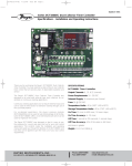
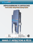
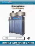
E-97-M:dcp100/200module IOM-4/01
8/18/09
4:22 PM
Page 1
Bulletin E-97-M
Series DCP100A/200A Pressure Modules
Specifications – Installation & Operating Instructions
1-13/16
[46.04]
1-11/16
[42.86]
1/2
[12.70]
1
[25.40]
2-7/16
[61.91]
The DCP100A or DCP200A pressure modules are designed exclusively for use with
the Dwyer® DCT1000 Dust Collector Timer
Controller boards for on-demand cleaning
requirements. These series of modules are
available in 10″ w.c. [2.49 kPa] or 20″ w.c.
[4.98 kPa] ranges, which allow for differential
process pressure measurement as indicated on the display of the master controller.
An isolated 4-20 mA readout channel is provided for remote pressure display. The 4-20
mA output may be wired either for use with
an external power supply and indicator or
using the isolated on-board 24 volt power
supply to power the loop.
SPECIFICATIONS
Pressure Ranges: 10˝ w.c. or 20˝ w.c.
Temperature Limits: -40 to 140°F
(-40 to 60°C).
Pressure Limit: 10 psi (68.95 kPa).
Pressure Limit (differential): 10 psi
(68.95 kPa).
Accuracy: ±1.5% F.S. @ 73°F (22.8°C).
Output Signal: 4-20 mA.
Alarm Contacts: 1.5A inductive load, 3A
resistive load @ 30 VAC or 40 VDC.
Process Connections: Two barbed connections for use with 1/8˝ (3.18 mm) or
3/16˝ (4.76 mm) I.D. tubing.
Weight: 5.5 oz (155.9 g).
Table
1.0
1.1
1.2
1.3
1.3.1
1.3.2
1.3.3
1.3.4
Table of Contents
Page No.
2.0 Demand Mode using a
DCP100A/200A Pressure
Module . . . . . . . . . . . . . . . . . . . .3
2.1 High Limit Setup . . . . . . . . . . . . . .4
2.2 Low Limit Setup . . . . . . . . . . . . . .4
2.3 High Alarm Setup . . . . . . . . . . . . .4
2.4 Low Alarm Setup . . . . . . . . . . . . .4
2.5 Auto Alarm Reset Setup . . . . . . . .4
of Contents
Page No.
Installation . . . . . . . . . . . . . . . . .2
Location . . . . . . . . . . . . . . . . . . . .2
Connections . . . . . . . . . . . . . . . . .2
Pressure Module Installation . . .2-3
Alarm Mode Switch Connection . .3
Alarm Reset Switch Connection . .3
Connecting the 4-20 mA loop . . .3
Connecting the Alarm Relay . . . . .3
DWYER INSTRUMENTS, INC.
P.O. BOX 373 • MICHIGAN CITY, INDIANA 46361,U.S.A.
Phone: 219/879-8000
Fax: 219/872-9057
www.dwyer-inst.com
e-mail: [email protected]
E-97-M:dcp100/200module IOM-4/01
8/18/09
4:22 PM
Page 2
NORMALLY OPEN CONTRACTS
RECEIVER
DAISY
CHAIN
OUT
TB4
DAISY
CHAIN
IN
4-20 MA
SOURCE
EXTERNAL
INTERNAL ALARM CONTACTS
RECEIVER
OPTIONAL
CONNECTION
USING EXTERNAL
POWER SUPPLY
MASTER CONTROLLER
INPUT MUST NOT BE
CONNECTED
TB5
ALARM
LOAD
MASTER CONTROLLER
TO ADDITIONAL
EXPANDER MODULES
DAISY
CHAIN
IN
DAISY
CHAIN
OUT
SUPPLY
TB2
TB3
4-20 MA
OUTPUT
USING DCT1000
24V SUPPLY
SUPPLY
ALARM MAN D1 ALARM
COM MODE OVR CLN RESETCOM
LOW
HIGH
LIMIT COM LIMIT
4-20 mA CONNECTIONS
C3Ø4
(INTERNALLY CONNECTED)
(10 CHANNEL SHOWN)
TB1
F1
L1
L2
LINE
INPUT
SOL
COM
1
2
3
4
5
6
7
8
9
10
SLAVE CHANNEL EXPANDER
SOLENOIDS
Fig. 1 - Switch
Connections
(INTERNALLY CONNECTED)
(10 CHANNEL SHOWN)
TB1
L1
L2
LINE
INPUT
3.0 Pressure Module Maintenance 4
1.0 Installation
Caution: Prior to installing the
DCP100A/200A please review the
operating specifications carefully.
Some operating systems, especially in
pneumatic conveying applications, may see
static pressure or vacuum conditions that
exceed
the
capability
of
the
DCP100A/200A pressure module. For
these conditions there are a number of
alternate Dwyer Instruments, Inc. pressure
products that can be used to meet your
application requirements, all of which can
be terminated to the Dwyer® DCT1000 Dust
Collector Timer Controller. For more information on these and other Dwyer® products, please call us at (219) 879-8000, or
visit us on the web at www.dwyer-inst.com
or www.dust-controls.com.
1.1 Location
The system should be located in an enclosure that meets relevant safety standards
and electrical codes. There are no other
special orientation requirements as the
pressure module is not orientation sensitive.
2
SOL
COM
1
2
3
4
5
6
7
8
9
10
SOLENOIDS
Care should be observed when routing the
air hoses to ensure that any potential condensation or moisture will not drain into the
sensor. Where heavy condensation is present, a drip loop or an in-line filter should be
installed to ensure long term operation.
1.2 Connections
When a pressure module is installed, the 420 mA process signal and the alarm relay
contacts are available. The circuit may be
used with the internal 24-volt power source
or with an external source. In either case,
the 4-20 mA circuit is isolated from ground
and other signals. The alarm relay contacts
are isolated, normally open contacts.
Pressure connections may be made to the
stepped hose barbs with either 1/8″ or
3/16″ I.D. tubing. The following subparagraphs describe the external switch connections. Refer to Figure 1 (above) for
switch connection illustration.
1.3 Pressure Module Installation
The pressure module is attached to the
Master Controller using integral connectors
on both units. The insertion ports for the
pressure module are located in the upper
E-97-M:dcp100/200module IOM-4/01
8/18/09
left quadrant of the DCT1000 Master
Controller. The pressure module can be
removed by compressing the retaining clips
on each end of the module, then gently
pulling the module out of the master controller board.
When inserting the module, the following
procedure should be adhered to insure
proper installation:
• Examine the bottom of the pressure module and note the orientation of the connectors.
• Align the module so that these connectors
match the connector receptacles on the
controller board.
• Orient the module with the four alignment
pins over their respective mounting holes.
• Gently press the module into the connectors and snap the retaining clips on either
end of the module into their slots.
• Always install and service this device with
the power off and a lockout installed if
required. “Hot” plugging the pressure module into an operating system may damage
the system or cause the calibration parameters to be erased.
Caution: Do not force the module
into the connectors. Forcing the
insertion may damage the connectors. Properly aligned, the module
should snap into place.
PRESSURE
MODULE
ALIGNMENT
PINS
LOCKING PINS INSERTED
ALL THE WAY INTO THE
CHANNEL
LOCKING PINS
INSERTED FROM
UNDERNEATH
MODULE ONLY
CIRCUIT
BOARD
4:22 PM
Page 3
alarm reset must be disabled. The switch
must be an isolated contact and wired such
that no connection is made between either
of the wires and ground.
1.3.2 Alarm Reset Switch Connection
The alarm may be reset either by pressing
the Alarm Reset button on the control panel
or by an external switch connected
between the alarm-reset terminal and one of
the common terminals. The alarm reset will
only operate if the pressure module is
installed and the pressure has returned to a
normal condition.
1.3.3 Connecting the 4-20 mA loop
The pressure module provides an isolated
4-20 mA output, which may be used to
remotely monitor the differential pressure
across the dust bags or cartridges. The
connection is made on the master control
module at the terminal block designated for
this signal. The connection is a 2-wire configuration with the option of using either an
external 15 to 35 VDC power source or
using the internal 24 VDC source.
1.3.4
Connecting the Alarm Relay
With the pressure module installed, a relay
contact is provided for controlling an external alarm. This relay is a single form-A contact. It is activated when either the high
alarm threshold is exceeded, or the pressure drops below the low alarm threshold.
The connection is made at the two-pin connector TB5.
2.0 Demand Mode using a
DCP100A/200A Pressure
Module
INSERT LOCKING PINS UNTIL THEY SNAP FIRMLY IN PLACE
1.3.1 Alarm Mode Switch Connection
The auto alarm reset is controlled by the
alarm mode switch connection. To enable
the auto alarm reset the alarm mode input
must be connected to a common connection. A jumper may be used when auto
alarm reset is always active. A switch may
be used if there are times that the auto
The DCT1000 system may be configured to
be a self-contained on-demand control system with the installation of the DCP100A
/200A pressure module. When this module
is installed, the master controller detects it
and automatically sets the system to an ondemand mode, enabling features associated with the pressure sensor. The following
subparagraphs describe the setup and
operation of these pressure related features.
3
E-97-M:dcp100/200module IOM-4/01
8/18/09
4:22 PM
Page 4
2.4 Low Alarm Setup
The operation of the Low Alarm Setup is
identical to the High and Low Limit Setup.
The Low Alarm default is 0.0″ w.c. The
upper setable value is the calibration pressure of the pressure module and the lower
limit is zero. Press the Select button until the
Low Alarm indicator is illuminated. Use the
Up and Down controls to set the limit to the
desired setting. Pressing both Up and
Down buttons simultaneously and holding
for about four seconds will restore the factory default.
2.1 High Limit Setup
The High Limit Setup sets the pressure at
which the cleaning cycle will begin. This
value may be between zero and the pressure module calibration pressure. Normally,
the High Limit should be above the Low
Limit. If, however, the High Limit pressure is
set below the Low Limit, the cleaning cycle
will begin when the High Limit is exceeded
and stop when the pressure falls below the
High Limit. The Low Limit in this case will
have no effect. Pressing both Up and Down
buttons simultaneously and holding for
about four seconds will restore the factory
setting for High Limit to 5.0″ w.c. [1.24 kPa].
2.5 Auto Alarm Reset Setup
The Auto Alarm Reset Setup mode allows
the auto alarm reset time to be selected.
This value may be set between zero and
255 seconds. The factory default value is
five seconds. When the auto alarm reset is
enabled by shorting the auto alarm reset terminal to a common terminal, the alarm will
be reset after the pressure returns to the
normal range and the selected timeout period has expired.
2.2 Low Limit Setup
The operation of the Low Limit mode is
identical to the High Limit mode except that
the default Low Limit pressure is 3.0″ w.c.
[0.75 kPa]. The upper setable value is the
calibration pressure of the pressure module
and the lower limit is zero. Press the Select
button until the Low Limit indicator is illuminated. Use the Up and Down controls to set
the limit to the desired setting. Pressing both
Up and Down buttons simultaneously and
holding for about four seconds will restore
the factory default.
3.0 Pressure Module
Maintenance
The pressure module should require very little maintenance under normal operational
conditions. However, periodic calibration
may be desirable to assure accuracy of the
readings. The module may be removed and
returned to the factory for calibration.
2.3 High Alarm Setup
The operation of the High Alarm Setup is
identical to the High and Low Limit Setup.
The High Alarm default is 0.0″ w.c. The
upper setable value is the calibration pressure of the pressure module and the lower
limit is zero. Press the Select button until the
High Alarm indicator is illuminated. Use the
Up and Down controls to set the limit to the
desired setting. Pressing both Up and Down
buttons simultaneously and holding for
about four seconds will restore the factory
default.
Still need help? Please feel free to contact one of our customer service representatives at 219879-8000 or visit us on the web at www.dwyer-inst.com or www.dust-controls.com. Thank you
for choosing Dwyer Instruments.
©Copyright 2009 Dwyer Instruments, Inc
Printed in U.S.A. 8/09
DWYER INSTRUMENTS, INC.
P.O. BOX 373 • MICHIGAN CITY, INDIANA 46361,U.S.A.
Phone: 219/879-8000
Fax: 219/872-9057
FR# 443123-01 Rev. 2
www.dwyer-inst.com
e-mail: [email protected]