1
Operating Instructions
SKC Deployable Cartridge
Sampler (DCS) System
SKC Inc.
863 Valley View Road
Eighty Four, PA 15330
Form #38048 Rev 0907
DCS System Quick Guide
Sampling Head and Cartridge Installation
1. Disassemble sampling head: Unscrew inlet from cartridge holder section. Unscrew
cartridge holder section from exhaust section. Clean parts and allow to dry.
2. Thread cartridge holder section onto exhaust section.
3. Insert cartridge into cartridge holder (arrow pointing toward exhaust).
4. Reinstall inlet section onto cartridge holder section.
Setup and Calibration
1. Set up sample pump. (See Leland Legacy® Quick Guide on page 9. For advanced
programming, see Leland Legacy Operating Instructions.)
2. Ensure cartridge is installed in sampling head.
3. Thread calibration adapter into sampling head inlet.
4. Use tubing with quick-connect fitting to connect pump inlet to outlet of sampling head.
5. Use short tubing to connect inlet of calibration adapter to outlet of calibrator.
6. Calibrate pump flow rate to 10 L/min and record the pre-sample flow rate.
7. Disconnect calibrator and remove calibration adapter from sampling head.
8. Mount bracket at desired location.
9. Install sampling head on mounting bracket.
10. Install rain cover on sampling head.
Sampling
1. Turn on pump and record pertinent data. (Leland Legacy pump may be started
manually or automatically, see Quick Guide on page 9.)
2. After desired sampling period, record sample stop time. Remove rain cover. Reinstate
calibration train to verify pump flow rate. Record post-sample flow rate.
3. Turn off pump. Record pertinent information.
4. Remove sampling head: Use quick-connect to detach tubing from pump inlet. Remove
tubing from sampling head. Remove sampling head from bracket. Move sampling head
to a clean area.
Sample Removal
1. Disassemble sampling head: Unscrew inlet from cartridge holder section.
2. Lift cartridge from cartridge holder section, wrap in aluminum foil, and place in supplied
Teflon® jar. Transport to lab.
SKC Inc., 863 Valley View Road, Eighty Four, PA 15330 • www.skcinc.com
Pre3
Table of Contents
Introduction ............................................................................................1
Performance Profile ...............................................................................2
Principle of Operation ............................................................................3
Media Preparation .................................................................................4
Cartridge Preparation ............................................................................4
Deployment of Cartridges for Field Sampling............................................................5
Sampling Head Preparation ..................................................................5
Cleaning the Sampling Head.....................................................................................5
O-ring Care for the Sampling Head ...........................................................................5
Inserting a Cartridge into the Sampling Head ...........................................................6
Sample Pump Operation .......................................................................7
Charging the Battery .................................................................................................7
Reading the Charging Status LED ............................................................................8
Battery Setup.............................................................................................................8
Battery Replacement .................................................................................................8
Leland Legacy Quick Guide ......................................................................................9
Calibration and Sampling ....................................................................10
Calibration ...............................................................................................................10
Sampling .................................................................................................................11
Sample Removal, Shipping, and Analysis ...........................................12
Removing the Cartridge from the Sampling Head...................................................12
Transporting Samples .............................................................................................12
Sample Storage.......................................................................................................12
Removing Filter and Sorbent from Cartridge...........................................................13
Analysis ...................................................................................................................13
Ordering Information............................................................................14
Li-Ion Battery Shipment .......................................................................15
Warranty ..............................................................................................16
Indicates a reminder or note
Indicates a warning or caution
Pre5
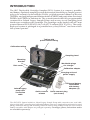
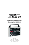
INTRODUCTION
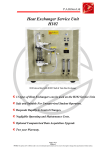
The SKC Deployable Cartridge Sampler (DCS) System is a compact, portable,
and battery-operated sampling system that ensures the ability to sample gaseous
polycyclic aromatic hydrocarbons (PAHs), polyhalogenated dibenzo-p-dioxins
(PHDDs), and polyhalogenated dibenzofurans (PHDFs) and particulate-associated
PHDDs and PHDFs in ambient air. The system features the fully programmable
constant flow Leland Legacy Sample Pump and an easy-to-use sampling head
that houses a stainless steel cartridge. The cartridge can be loaded with a 47-mm
quartz filter and PUF (EPA TO-9A) or XAD®-2 sorbent (EPA TO-13A). The easily
deployed system is packaged in a portable heavy-duty Pelican® case from which
the system operates.
Tubing with
quick-connect fitting
Calibration tubing
Sampling head
Mounting
bracket
Worldwide plugs
for charger
Rain cover
Calibration adapter
Charging unit and
power supply
Leland Legacy
pump with
connection
cable
External battery
assemblies
with battery
adapters (2)
Quick-connect
release
Quick-connect plug
(not shown)
The SKC DCS System includes a Leland Legacy Sample Pump with connection case and cable,
charger (100-240 V), sampling head, calibration adapter, rain cover, sample tubing with quick-connect
fitting, calibration tubing, and mounting bracket in a heavy-duty lockable carry case. Two external
battery assemblies with adapters are packaged separately. Cartridges, filters, and sorbent media
are available separately.
1
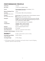
PERFORMANCE PROFILE
Flow Rate:
10 L/min
Run Time:
> 24 hrs on one battery charge
Power:
Rechargeable lithium-ion (Li-Ion) battery, 7.4 V,
12-Ah capacity†, 88.8 Wh
Battery Recharge Time:
15 hrs
Pre-filter:
47-mm quartz, QM-A, 450-μm thickness
Sorbent:
EPA TO-9A: PUF (polyether type), 40-mm diameter, cleaned
or
EPA TO-13A: XAD-2 sorbent, cleaned
Analysis:
TO-13A: Gas chromatography/mass spectrometry (GC/MS)
TO-9A: High resolution gas chromatography/High resolution
mass spectrometry (HRGC/HRMS)
Tubing:
3/8-in ID reinforced flexible PVC (supplied)
Temperature:
Charging: 32 to 113 F (0 to 45 C)
Operating: 32 to 113 F (0 to 45 C)
Storing:
-4 to 95 F (-20 to 35 C)
Altitude:
Do not use pump beyond 7500 ft.
RFI/EMI Shielding:
CE marked
Case Dimensions:
18.5 x 14.1 x 6.9 in (47 x 36 x 18 cm)
(Not supplied with system)
(Not supplied with system)
Complete System Weight: 12.20 lbs (5.5 kg)
Sampling Head
Dimensions:
2.6 dia. x 3.6 H x 3.8 L in (7 x 9 x 10 cm)
Sampling Head Weight:
0.60 lb (.27 kg)
Cartridge Weight:
0.75 lb (.34 kg)
(without cartridge)
† DCS Systems contain Li-Ion batteries and may be subject to special shipping
regulations dependent upon quantity.
2
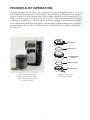
PRINCIPLE OF OPERATION
A sample pump draws air at a flow rate of 10 L/min through nozzles on top of
the sampling head and into the cartridge. The cartridge is designed to be loaded
with a cleaned 47-mm quartz filter that collects particles and cleaned PUF or
XAD-2 sorbent that adsorbs gases and vapors. The aluminum foil-wrapped
cartridge is supplied in a Teflon jar so that the sample is protected from light
and contamination during transport. The filter and sorbent media are combined
for extraction followed by GC/MS analysis for EPA TO-13A or HRGC/HRMS for
EPA TO-9A.
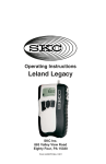
Inlet section
Teflon O-ring
Cartridge holder
section
BUNA-N O-ring
Exhaust section
DCS Sample Head and
Leland Legacy Sample Pump the two main components of
the DCS System
Exploded view of the
DCS Sample Head
3
MEDIA PREPARATION
For Laboratory Use
Use clean hexane-rinsed Teflon-tipped forceps to handle filters.
Wear disposable, clean, lint-free nylon or powder-free surgical gloves
to handle the sorbent and cartridge.
Quartz Filter: Prepare following the procedure outlined in EPA TO-9A or
TO-13A, Section 10.2.1. (http://www.epa.gov/ttnamti1/airtox.html)
XAD-2 Sorbent: Purchase precleaned or use procedure outlined in EPA TO13A, Section 10.2.5.
PUF: Purchase precleaned or use procedure outlined in EPA TO-9A or TO-13A,
Section 10.2.4.
CARTRIDGE PREPARATION
For Laboratory Use
Use clean hexane-rinsed Teflon-tipped forceps to handle filters.
Wear disposable, clean, lint-free nylon or powder-free surgical gloves
to handle the sorbent and cartridge.
1.
2.
3.
4.
5.
6.
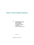
Rinse cartridge with appropriate organic solvent and allow to dry.
Ensure Teflon gasket 1, the stainless steel support screen 1, and Teflon
gasket 2 are in place on bottom cartridge cap.
Insert PUF or XAD-2 into the cartridge.
Top
Ensure the Teflon gasket 3 and stainless
cartridge cap
steel screen 2 are in place on cartridge
Teflon gasket 4
body top.
Insert
47-mm t
Using cleaned forceps, align quartz filter
Stainless steel
filter
support screen 2
with screen radially, and place Teflon
gasket 4 on top of filter. Thread top
Teflon gasket 3
cartridge cap onto cartridge.
Wrap the cartridge with hexane-rinsed
Insert
Stainless steel
PUF or
cartridge body
aluminum foil, place in supplied Teflon
XAD-2 t
sorbent
jar, and label jar. Analyze (certify) at least
1 cartridge from each batch of cartridges
Teflon gasket 2
prepared using the procedure described
Stainless steel
in Section 10.3 of EPA TO-9A or EPA
support screen 1
TO-13A (http://www.epa.gov/ttnamti1/
Teflon gasket 1
airtox.html) prior to field use. See Section
10.3.8 for acceptable background levels.
Bottom
cartridge cap
Cartridges are considered clean for up to
30 days from date of certification when
Cartridge for EPA TO-13A
sealed in their containers.
4
Deployment of Cartridges for Field Sampling
Immediately prior to field deployment, follow the procedure in EPA TO-9A or
TO-13A, Section 10.4.
SAMPLING HEAD PREPARATION
Cleaning the Sampling Head
All cleaning, loading, and unloading should be conducted in a controlled
environment to minimize any chance of potential contamination. When new
or when using the sampler at a different location, all sample contact areas need
to be cleaned. Rinse with appropriate organic solvent. Allow the solvent to
evaporate before loading a cartridge.
For deployed applications where method-specified solvents are
unavailable, use isopropyl (rubbing) alcohol or a clean tissue wipe.
Do not place any mechanical object in the inlet nozzles.
O-ring Care for the Sampling Head
Visually inspect the condition of the BUNA-N exhaust O-ring (see illustration
on page 3 for location). Ensure the O-ring surface is smooth (i.e., without cracks,
cuts, or other damage). Ensure the O-ring is fitted properly in its channel.
Replace the exhaust O-ring if there is apparent damage, stretching, or thinning.
It is recommended that the Teflon inlet O-ring be replaced by the manufacturer
only.
5
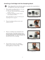
Inserting a Cartridge into the Sampling Head
Wear disposable, clean, lint-free nylon or powder-free surgical gloves
to handle the sorbent and cartridge.
1.
Disassemble sampling head (see drawing
on page 3 for placement of parts).
a. Unscrew inlet section from cartridge
holder section.
b. Unscrew cartridge holder section
from exhaust section.
1
Inlet
section
Clean and allow to dry (see Cleaning the
Sampling Head on page 5).
2.
Cartridge Exhaust
holder
section
section
Disassemble sampling head.
Thread cartridge holder section onto
exhaust section.
Thread cartridge holder onto
exhaust section.
3.
Remove cartridge from aluminum foil
and insert into cartridge holder section.
Ensure airflow arrow on cartridge points
to exhaust section. The filter should be on
the inlet side of the cartridge.
Insert cartridge into cartridge
holder section.
4.
Thread inlet section onto cartridge
holder section until just tight. Further
hand-tighten by 1/4 turn only.
4
Thread inlet section onto cartridge
holder section.
6
SAMPLE PUMP OPERATION
The user may choose to:
• Operate the pump manually in the field (on/off )
• Program a schedule into the pump manually
• Program the pump for multiple schedules from a PC
with optional DataTrac® for Leland Legacy Software
(see Ordering Information, Accessories on page 14).
See page 9 for a Quick Guide to operate the SKC Leland
Legacy Sample Pump. For advanced programming, see the
complete Leland Legacy Pump Operating Instructions.
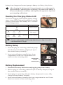
Charging the Battery
Completely charge a new battery pack using the SKC-approved charger (Cat. No.
223-241) before operating the pump. It may be necessary to charge the battery a
few times before maximum battery capacity is achieved.
Cautions:
• Do not charge or operate pump with or without charger in hazardous
locations.
• Use only the SKC-approved charger for this pump. Use of an
unapproved charger may damage the battery and pump.
• Use of a non-approved charger voids any warranty.
• Do not open, disassemble, short circuit, crush, incinerate, or expose the
battery to fire or high temperatures.
• Tampering with the battery pack voids any warranty.
• Ensure proper orientation of charging cable before plugging it into the
charging jack. Improper orientation/contact will short-circuit the battery
and voids any warranty.
• Short-circuiting the battery pack will render it immediately inoperative.
• Failure to follow warnings and cautions voids any warranty.
The battery pack may be kept on the SKC-approved charger for an
indefinite time.
1. Insert the plug from the charging unit into the
charging port on the battery adapter (on top of the
external battery assembly).
2. Insert plug from power supply into the jack on the
charging unit.
3. Install the appropriate wall plug on the power
supply and plug power supply into a wall outlet.
The battery will recharge in approximately 15
hours. For a complete charge, do not run the pump
connected to the external battery assembly during
charging. After charging is complete, disconnect
7
Battery
adapter
External
battery
assembly
1
Power
supply
Charging
unit plug
External
Charging battery
assembly
unit
battery from charger and connect pump to battery (see Battery Setup below).
After charging the battery pack, it is good practice to run the pump for
approximately 5 minutes before calibrating. This ensures the battery is
in more steady-state conditions and improves the agreement in pre and
post-sampling calibrations.
Reading the Charging Status LED
Power supply jack
The Li-Ion Charging Unit indicates battery charge
status via an LED on the unit that blinks in specific
patterns. Observe the LED steadily for > 5 seconds
to read charge status.
LED Action
Charge Status
ON
Ò
steady
Charge in progress
ON
Ò
2 sec
OFF
{
.25 sec
ON
Ò
2 sec
(Repeats)
Approximately
80% charged
OFF
{
2 sec
ON
Ò
.25 sec
OFF
{
2 sec
(Repeats)
Charge completed
Charge status LED
For more information on SKC pump batteries, go to http://www.skcinc.
com/instructions/1756.pdf.
Battery Setup
1. Insert the plug on connecting cable from pump
into the jack on the battery adapter (on top of
the external battery assembly).
1
2. Insert external battery assembly into a foam
compartment in the case. Ensure there is no
tension on the connecting cable.
External battery
assembly
Connecting cable
Battery Replacement
1. Record all necessary data before unplugging pump from battery.
2. Remove plug on connecting cable from jack on battery adapter (on top of
the external battery assembly).
3. Insert plug on connecting cable into battery adapter jack on new, fully
charged external battery assembly.
4. Insert external battery assembly into foam compartment in case. Ensure
there is no tension on the connecting cable.
8
Leland Legacy Quick Guide
Terms »
Star button Ò
• Scrolls through run time data and Setup options
Up and down arrow buttons ST
• Toggle between display choices and increase or decrease sampling parameters in Setup
Button sequence
T Ò= press buttons individually
[ST] = press simultaneously
ÒSTÒ = security code, always press in sequence
Security code ÒSTÒ
• Prevents unauthorized changes to the pump’s sampling program
Programming Sequences »
• To activate pump (e.g., to change pump from Sleep to Hold):
Press any button.
• To change pump from Hold to Run or Run to Hold:
Press [ST].
• To reset accumulated data:
Press [ST], then ÒSTÒ. Press Ò until CLr displays then press [ST]; press Ò until End displays then
press [ST].
• To set pump flow rate:
Press [ST], then ÒSTÒ. Flow rate and SET flash. Press S or T to change flow rate. Press Ò until End
appears then press [ST] to save setting and place pump in Hold.
• To calibrate flow rate with standard calibrator:
Press [ST], then ÒSTÒ. Flow rate and SET flash. Press S or T to change flow rate. Press Ò once. ADJ
displays. Press S or T until desired flow rate is indicated on calibrator. When finished, press Ò until End displays
then press [ST] to save new setting and place pump in Hold. For CalChek Calibration, see operating instructions.
• To change temperature scale from F to C or C to F:
Press [ST], then ÒSTÒ. Press Ò until temperature displays. Press S or T to switch units; press Ò until
End displays then press [ST] to save new setting.
• To change atmospheric pressure scale (mm, mb, In):
Press [ST], then ÒSTÒ. Press Ò until pressure displays then press S or T to switch units; press Ò until
End displays then press [ST] to save new setting.
• To change time scale (12 Hr/24 Hr/Dela):
Press [ST], then ÒSTÒ. Press Ò until 12 Hr, 24 Hr, or Dela displays then press S or T to switch units;
press Ò until End displays then press [ST] to save new setting. To set delayed start (Dela), see operating
instructions.
• To change clock:
Press [ST], then ÒSTÒ. Press Ò until clock displays then press S or T to change flashing hour; press Ò to
move to minutes and S or T to change setting. Press Ò until End displays then press [ST] to save new setting.
• To change the sampling time function:
Press [ST], then ÒSTÒ. Press Ò until ST L/min displays then press S to change flashing digit; press Ò until
End displays then press [ST] to save new setting. To delete, follow above steps and press T until 0 appears.
Exit Setup.
Note: When in Setup, choosing Esc instead of End will exit Setup without saving new settings.
SKC Inc., 863 Valley View Road, Eighty Four, PA 15330 • www.skcinc.com
9
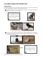
CALIBRATION AND SAMPLING
Calibration
Calibrate pump flow rate with the sampling head loaded with a cartridge in
line. See pump and calibrator operating instructions.
Wear disposable, clean, lint-free nylon or powder-free surgical gloves to
handle the sorbent and cartridge.
Ensure pump has run for 5 minutes
before calibrating. Ensure rain
cover is removed from inlet and
that sampling head is completely
assembled with a fully loaded
cartridge (see Inserting a Cartridge
into the Sampling Head).
1
Thread calibration adapter into
sampling head inlet.
Inlet line
to pump
Inlet
Quickconnect
plug
Quickconnect
fitting on
tubing
Unscrew quick-connect plug on side of case. Use tubing with quick-connect
fitting to attach case (pump) inlet to exhaust of sampling head.
Ensure O-ring is installed on the quick-connect fitting before inserting it
into the inlet. Absence of the O-ring can affect measurements. See page 14
for Replacement Parts.
Use provided short length of calibration tubing to connect inlet of calibration
adapter to outlet of a calibrator to form a calibration train.
Inlet to Calibration adapter
pump
Flowmeter
outlet
Sample
head
outlet
Set and calibrate pump flow rate to 10 L/min (see Leland
Legacy Quick Guide on page 9). Record the pre-sample flow
rate. See pump and calibrator operating instructions.
10
When calibration is completed,
disconnect calibrator and tubing
from calibration adapter. Remove
calibration adapter from sampling
head.
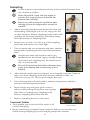
Sampling
Locate system in an unobstructed area, at least 6 feet (2 meters) from
any obstacle to airflow.
Wear disposable, clean, lint-free nylon or
powder-free surgical gloves to handle the
sorbent and cartridge.
Before use, allow pump to equilibrate after
moving it from one temperature extreme to
another.
1.
Attach mounting bracket at the desired location and
at breathing zone height (6 ft or 2 m) using wire ties
or other fasteners. Mount sampling head loaded with
cartridge on mounting bracket by threading clamp
knob into bottom of sampling head.
2.
Insert screw on rain cover into top of the sampling
head inlet and rotate cover until tight.
3.
Turn on pump and record sample start time, ambient
temperature, ambient pressure, and other pertinent
data.
1
Sample start time and duration can be programmed into the Leland Legacy Sample Pump
in advance and sampling may be started manually or automatically.
Record all necessary data before disconnecting
pump from battery and reconnecting to new
battery.
3
4.
After desired sample time has elapsed, record sample stop time. Remove
rain cover from sampling head and reinstate calibration train (see
Calibration on page 10). Record post-sample flow rate.
5.
Turn off pump. Record total volume, ambient temperature, ambient
pressure, and other pertinent data.
6.
Reach inside case and press quick-connect
release while pulling tubing from case (pump)
inlet. Remove tubing from sampling head.
Remove sampling head from bracket.
7.
Remove sampling head to a clean area.
Quick-connect
release inside
case
6
Technical Tidbits
Tubing with
quick-connect
fitting
Press quick-connect release to
• The supplied rain cover should be used for all
remove tubing.
outdoor sampling.
• Keep Leland Legacy Sample Pump inside the Pelican case and the case
closed during sampling to protect sample pump from weather.
11
SAMPLE REMOVAL, SHIPPING, AND
ANALYSIS
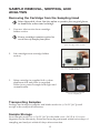
Removing the Cartridge from the Sampling Head
Wear disposable, clean, lint-free nylon or powder-free surgical gloves
to handle the sorbent and cartridge.
1.
Unscrew inlet section from cartridge
holder section.
Ensure cartridge remains vertical to
avoid loss of sample from filter.
1
Remove inlet section
from cartridge holder section.
2.
Lift cartridge from cartridge holder
section.
Lift cartridge from cartridge
holder section.
3.
Wrap cartridge in supplied foil or clean
aluminum foil and place in supplied
Teflon jar to protect sample from light and
contamination.
3
Wrap cartridge in foil and
insert in Teflon jar.
Transporting Samples
Package and transport samples and blanks under ice (< 39.2 F [4 C]) until
receipt at the analytical laboratory.
Sample Storage
Store samples under ice (< 39.2 F [4 C]) in the field or at < 39.2 F (4 C) in a refrigerator in the laboratory. Extraction must be performed within seven days of
sampling and analysis within 40 days after extraction.
12
Removing Filter and Sorbent from Cartridge
For Laboratory Use Only
1. Remove filter and sorbent(s) from cartridge.
2. Combine for extraction.
3. a. For XAD-2 sorbent: Use procedure outlined in EPA TO-13A, Section
12.2.
b. For PUF sorbent: Use procedure outlined in EPA TO-9A, Section 12.1.
Analysis
TO-13A: Gas chromatography/mass spectrometry (GC/MS)
TO-9A: High resolution gas chromatography/High resolution mass
spectrometry (HRGC/HRMS)
13
ORDERING INFORMATION
Description
DCS System† includes a Leland Legacy Sample Pump with connection
case and cable, charger (100-240 V), sampling head, calibration
adapter, rain cover, sample tubing with quick-connect fitting, calibration
tubing, and mounting bracket in a heavy-duty lockable carry case. Two
external battery assemblies with adapters are packaged separately.
Cartridges, filters, and sorbent media available separately
Cat. No.
100-3960
† DCS Systems contain Li-Ion batteries and may be subject to special shipping regulations dependent
upon quantity.
DCS Cartridges
DCS Cartridge Marked for TO-9A, supplied without media in Teflon jar 226-200
DCS Cartridge Marked for TO-13A, supplied without media in Teflon jar 226-201
Media
Required. Not included in system. Select based on application.
PUF, (polyether type), 40-mm diameter, cleaned, each PUF wrapped in
foil and supplied in glass jar with lid, pk/3
XAD-2 Sorbent, 100 gm, 20/60 mesh size, cleaned, supplied in glass
jar with lid
Quartz Filter, QM-A, 47 mm, 450-μm thickness, pk/100
Accessories
Forceps, stainless steel
DataTrac® for Leland Legacy Software includes software on CD,
DataTrac adapter, DataTrac cable, requires Windows 98 or higher and
available serial port or USB to serial adapter that is compatible with the
PC and system
Replacement Parts
DCS Sampling Head
Quick-connect Fitting O-rings, pk/3
Rain Cover, grey
Mounting Bracket
Stainless Steel Support
Quick-connect Fitting, on 6.5-ft reinforced flexible PVC tubing
Reinforced Flexible PVC Tubing, 6.5 ft
Calibration Tubing, 1 ft, reinforced flexible PVC
Silicone Tubing, 0.4 ft, pk/2
DCS Case, Pelican, with foam and hardware
Calibration Adapter
Mass Flow Controller
Leland Legacy Pump Operating Instructions
Leland Legacy Pump Quick Guide
Quick-connect Plug with retaining chain
External Battery Assembly with battery adapter
Battery Adapter
Connection Case with cable and plug
14
P226DCS
P226201
225-1811
225-8371
877-92
Cat. No.
225-620
P31996
225-398
225-399
225-2647A
P42741
P30004
P300041
P30255A
225-3901
225-394
P16110
P40075
P37138
P42742
223-247
223-248
223-249
LI-ION BATTERY SHIPMENT
Rechargeable, lithium-Ion batteries for use with SKC sampling pumps have been
tested in accordance with the UN Manual of Tests and Criteria and are designated
as UN3091. They have a watt-hour (Wh) rating below 100.
For air shipments:
Per 2009 IATA regulations, packaging must meet the specifications of and contain
labeling and documentation required by IATA Packing Instructions 965, 966, and
967. Per these instructions:
• Boxes containing Li-Ion batteries only cannot exceed a maximum gross
weight of 22 lbs (10 kg).
• The maximum number of batteries packed with equipment is the number
required to power equipment in the box plus 2 spare batteries per unit.
• There is no maximum limitation for batteries contained within equipment.
For ground shipments:
U.S. DOT regulations specify a limit of 24 or fewer battery cells in one shipping
box. To be exempt from Dangerous Goods Shipping requirements, the box must
contain 24 or fewer cells. Therefore, limit any box to be shipped via ground to
the following number of pumps:
• Leland Legacy Pump - 2 pumps
Contact SKC for more information or refer to the regulatory authority in your
area.
15
SKC INC.
LIMITED ONE YEAR WARRANTY
1. SKC warrants that its instruments provided for industrial hygiene, environmental, gas
analysis, and safety and health applications are free from defects in workmanship and materials under
normal and proper use in accordance with operating instructions provided with said instruments. The
term of this warranty begins on the date the instrument is delivered to the buyer and continues for a
period of one (1) year.
This warranty does not cover claims due to abuse, misuse, neglect, alteration, accident,
or use in application for which the instrument was neither designed nor approved by SKC Inc. This
warranty does not cover the buyer’s failure to provide for normal maintenance, or improper selection
or misapplication. This warranty shall further be void if changes or adjustments to the instrument are
made by other than an employee of the seller, or if the operating instructions furnished at the time of
installation are not complied with.
2. SKC Inc. hereby disclaims all warranties either expressed or implied, including any implied
warranties of merchantability or fitness for a particular purpose, and neither assumes nor authorizes
any other person to assume for it any liability in connection with the sale of these instruments. No
description of the goods being sold has been made a part of the basis of the bargain or has created or
amounted to an express warranty that the goods will conform to any such description. Buyer shall not
be entitled to recover from SKC Inc. any consequential damages, damages to property, damages for
loss of use, loss of time, loss of profits, loss of income, or other incidental damages. Nor shall buyer be
entitled to recover from SKC Inc. any consequential damages resulting from defect of the instrument
including, but not limited to, any recovery under section 402A of the Restatement, Second of Torts.
3. This warranty extends only to the original purchaser of the warranted instrument during
the term of the warranty. The buyer may be required to present proof of purchase in the form of a paid
receipt for the instrument.
4. This warranty covers the instrument purchased and each of its component parts.
5. In the event of a defect, malfunction, or other failure of the instrument not caused by any
misuse or damage to the instrument while in possession of the buyer, SKC Inc. will remedy the failure or
defect without charge to the buyer. The remedy will consist of service or replacement of the instrument.
SKC Inc. may elect refund of the purchase price if unable to provide replacement and repair is not
commercially practicable.
6. (a) To obtain performance of any obligation under this warranty, the buyer shall return the
instrument, freight prepaid, to SKC Inc., at the following address:
SKC Inc., National Service Center
863 Valley View Road
Eighty Four, PA 15330 USA
(b) To obtain return authorization information or for further information on the warranty
performance you may telephone 724-941-9701 at the above address. See Service Policy section in
operating manual (if applicable).
7. This warranty shall be construed under the laws of the Commonwealth of Pennsylvania
which shall be deemed to be the situs of the contract for purchase of SKC Inc. instruments.
8. No other warranty is given by SKC Inc. in conjunction with this sale.
Form #3755 Rev 0207
16
17
www.skcinc.com
Notice: This operating instruction may not address all safety concerns (if any) associated with this product and its use. The
user is responsible for determining and following the appropriate safety and health practices and regulatory limitations (if
any) before using the product. The information contained in this document should not be construed as legal advice, opinion,
or as a final authority on legal or regulatory procedures.
18