1
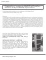
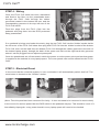
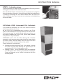
Operating Instructions
FUYL Cell™
www.lockncharge.com
FUYL Cell™
Congratulations on your purchase of the FUYL Cell. Follow these
instructions for easy and fast set-up of your FUYL Cell.
LocknCharge and the Padlock device are Trademarks of IWS Global Pty Ltd.
Copyright IWS Global Pty Ltd, November 2012.
Disclaimer.
This information is the intellectual property of LocknCharge and may not be distributed, duplicated or
copied in part or full without the written permission. Since the use of this information, the equipment
connected and the conditions by which any LocknCharge product is used is beyond the control of
LocknCharge, it is the obligation of the owner and/or user to determine the correct and safe use of
any equipment and product. To the extent that the law permits, any liability which may be incurred
as a result of the use or future use of a product manufactured or sold by LocknCharge. is limited to
the cost of repairing or replacing the failed product or component at the discretion of LocknCharge
either within, or outside of warranty periods, and does not extend to any loss or damage which may
be caused as a consequence of misuse or failure of the equipment or product or the information
contained herein. LocknCharge. shall not in any event be liable for economic loss of profits, indirect,
special, bodily injuries or consequential damages.
FUYL Cells can be stacked one on top of the other and fixed
to the floor either with or without the optional pedestal. The
maximum number of FUYL Cells in a stack is 3.
UNDER NO CIRCUMSTANCES STACK MORE THAN 3
FUYL Cells
INSTALLING THE FUYL Cell STACK
Identify the desired location for the stack, ideally where a
powerpoint is located low on a wall. The pedestal has an
opening at the lower back to allow access to a wall powerpoint.
If a pedestal is not being used the power lead will exit the
stack on the right hand side. These instructions are for fixing
to a solid concrete floor using the supplied Dynabolts. Other
floor types may be suitable but a qualified structural engineer
should give advice on this.
www.lockncharge.com
INSTRUCTION MANUAL
STEP 1
First remove the Joiner Ring from one of the FUYL Cells that
will become the bottom FUYL Cell of the stack.
STEP 2 - Remove the FUYL Cell side panel
•
Open all doors
•
Unscrew 5 x Phillips head screws on LHS of the front panel.
•
Remove the side panel using this technique – Gently pull the front edge of the side panel out
(sideways) from the front (no more than 40mm). Then carefully slide the panel forward to release
its lugs from the rear.
Either the FUYL Cell Joiner Ring or the Pedestal can be fixed to
the floor using the 50mm Dynabolts provided. Once in place fix
the M6 studs in place using a screwdriver. Now locate the bottom
FUYL Cell (now without the Joiner Ring) on top of the Joiner Ring
or Pedestal. The 4 studs should locate up through the holes in the
Bottom of the FUYL Cell. Install the M6 nuts and tighten.
M6 Stud Holes
Please refer to the FUYL Cell schematic for more details
(back of the booklet).
Dynabolt hole
STEP 3
Now remove the left side panel for the FUYL Cells to be installed above (as described above) to
gain access to the LHS upper/lower, front and rear fixing holes. The RHS holes are in the Laptop
spaces - front and rear. Turn the next FUYL Cell in the stack upside down and locate the M6 studs in
the joiner ring, then fix the FUYL Cell in place. Locate the third FUYL Cell in the same way.
For additional stability of the FUYL Cell stack, it can be secured to the wall behind it using 75mm
Dynabolts provided, through the two top rear holes in the top FUYL Cell, providing the FUYL Cell
stack is located hard up against the wall, this will stop any possible sideways movement in the FUYL
Cell stack.
FUYL Cell™
STEP 4 - Wiring
Once the FUYL Cell stack has been assembled
and fixed to the floor run the powerleads down
through the FUYL Cells through the rubber
grommets located in the bottom left rear, and the
corresponding grommet in the top left rear of the
FUYL Cell below.
Feed the plugs from the FUYL Cells into the
pedestal and plug them into the RCD protected
4way powerboard.
If no pedestal is being used under the stack, plug the top FUYL Cell into the ‘hidden’ socket inside
the left cover of the FUYL Cell below then plug that FUYL Cell into the ‘hidden’ socket of the bottom
FUYL Cell, then run the lead from the bottom FUYL Cell through the rubber grommet in the side of
the bottom laptop space, through the back of the space and exit out the right hand side grommet
where it can be plugged into an adjacent powerpoint.
Once the powerleads are all connected, switch the power on at the power point and test that power
is supplied to the sockets in every laptop space. The cover panels can now be refitted into the FUYL
Cells.
STEP 5 - Electrical Reset
In the event that the electrical system is ever overloaded it will automatically switch itself off. The
reset button is located on the “Hidden” socket.
(Note: The side panel has been removed for clarity – it does not need to be removed to reset switch)
In the event of a serious power flaw the RCD switch in the pedestal may trip. This should be reset. If it
immediately trips again, every power board in every laptop space will need to be checked.
www.lockncharge.com
INSTRUCTION MANUAL
STEP 6 - Adjusting doors
The final process is to align the doors so that they fit evenly over the
locking pins and are in line with each other. Once the FUYL Cell is secured it may be necessary to re-align the
doors so that they fit properly. Using the small Allen key, adjustment
is made by loosening the small socket bolts inside the door and
either lifting the door up or down as is necessary, and retightening
the socket bolts.
OPTIONAL STEP - Alternate FUYL Cell stack
It is possible to assemble the FUYL Cell stack so that the
doors do not all face the front.
As the FUYL Cell is assembled one or more of the FUYL
Cells can be rotated prior to being bolted to the stack below.
The locating holes for the M6 socket bolts are uniform on
the corners enabling the FUYL Cells, joiners and pedestal
to be joined in any orientation.
HOWEVER, care must be taken during this alternate
assembly as the grommets through which the power leads
run will be offset, and the lead(s) from the top FUYL Cells
will not reach down into the bottom of the stack.
These issues are overcome by:
a. Running the lead from the FUYL Cell above, through
the joiner ring and down through the grommet prior to
assembling the FUYL Cells together, and
b. Adding a short 1 or 2m extension cord (not supplied)
from the upper FUYL Cells to get sufficient cord length.
Plugs and sockets can be ‘hidden’ behind the left hand
access panels.
FUYL Cell™
WARRANTY
During the specified Warranty Period should your Lock’n’Charge product fail under normal and
reasonable use, Lock’n’Charge Technologies will repair or replace the product, at its cost and option
subject to the conditions and limitations detailed on our Warranty Statement. The Warranty Period will
be a minimum of 12 months from date of purchase, however, it may be longer depending on the product
or part that has failed. Please refer to the Warranty Statement on our website www.lockncharge.com
for full terms and conditions and for the Warranty Period applicable to this product.
In the event that a defect, malfunction or failure occurs or is discovered during the warranty period,
LocknCharge will repair or replace, at its option, the products which in the reasonable judgment of
LocknCharge are deemed defective. Replacement products or parts used may be new or refurbished
and may show signs of use but be otherwise fully serviceable and covered by the remainder of the
Warranty Period. All transportation costs shall be borne by the owner and the risk of loss shall be upon
the party initiating the transportation.
The warranty does not apply to any product that has been subject to misuse, tampering, neglect, or
accident or as a result of unauthorized alterations or repairs to the product. The warranty is in lieu of
all warranties expressed or implied, including the implied warranties of merchantability and fitness for
a particular purpose which are expressly excluded or disclaimed. In no event will LocknCharge, their
directors, officers, employees, or agents be liable for any harm, consequential, incidental, third party,
special or indirect damages whatsoever arising out of the use or inability to use the products even if
LocknCharge has been advised of the possibility of such damages. LocknCharge obligation is strictly
and exclusively limited to the replacement or repair of any defective products. Some states do not allow
the exclusion or limitation of incidental or consequential damages, so the above limitation or exclusion
may not apply to you.
Do not store in direct sunlight. Not intended for use out-doors.
www.lockncharge.com
Compliance and approvals
AUSTRALIA:
C-Tick Approval: N26682
Conforms to AS/NZS 60950.1
USA:
This device complies with Part 15 of the FCC Rules. Operation is subject to the following two
conditions:
1. This device may not cause harmful interference.
2. This device must accept any interference received, including interference that may cause
undesired operation.
Warning: Changes or modifications to this unit not expressly approved by the party responsible for
compliance could void the user’s authority to operate the equipment.
Responsible Party: Lock and Charge USA Inc, 307 6th St. W. West Fargo, ND 58078-1533, (701)
630-9357, [email protected]
NOTE: This equipment has been tested and found to comply with the limits for a Class B digital
device, pursuant to Part 15 of the FCC Rules. These limits are designed to provide reasonable
protection against harmful interference in a residential installation. This equipment generates,
uses, and can radiate radio frequency energy and, if not installed and used in accordance with
the instructions, may cause harmful interference to radio communications. However, there is no
guarantee that interference will not occur in a particular installation. If this equipment does cause
harmful interference to radio or television reception, which can be determined by turning the
equipment off and on, the user is encouraged to try to correct the interference by one or more of the
following measures:
• Reorient or relocate the receiving antenna.
• Increase the separation between the equipment and receiver.
• Connect the equipment into an outlet on a circuit different from that to which the receiver is
connected.
• Consult the dealer or an experienced radio TV technician for help.
“This Class B digital apparatus complies with Canadian ICES-003”. “Cet appareil numérique de la
classe B est conforme à la norme NMB-003 du Canada”.
Shielded USB cable must be used with this unit to ensure compliance with the Class B FCC limits.
www.lockncharge.com