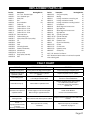
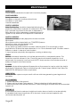
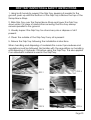
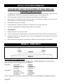
1
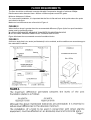
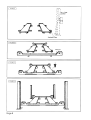
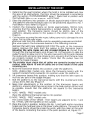
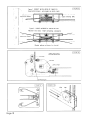
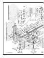
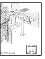
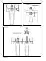
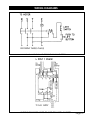
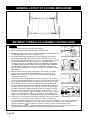
Molnar Engineering Pty. Ltd
Installation
Operation
Maintenance
Instructions
MOLNAR
Four Post
Hoist Models:
3585 & 4488
OPTIONAL 240 VOLT SINGLE PHASE
MINIMUM REQUIREMENTS FOR ELECTRICAL CONNECTION OF MOLNAR
HOISTS
Important: All installations should be carried out by suitably
qualified persons. Failure to comply may void warranty.
The following information is a guide only based on the
latest standards as set out in AS/NZS 3000, for installations
outside of Australia & New Zealand refer to local
standards/regulations.
Circuit Breakers should be of “D” curve type (motor start,
high inrush current) - Ratings given as a maximum for
circuit & motor protection based on DOL selection guide.
Voltage operating range: -6% to +10% of motor
nameplate Voltage.
Motor Voltage 240V Operation range 225V to 264V.
Cable sizes are given as a guide only for a maximum
cable length to 30m. Longest cable runs and in area
where supply voltage is below motor voltage, calculation
should be made to ensure Voltage Drop will not fall
below minimum operating voltage.
When installed motors must be tested under Full Load checking
Voltage at motor terminals.
Motor 2.2kW 240V Single phase model CWC3640F
Full Load Current
Min Cable Size
Circuit Breaker
12.4 Amps
2.5mm 2 core + earth
1 phase 32 Amp 10kA
Recommended Clipsal 4CB132/10 or equivalent
No person should be permitted to operate
the MOLNAR FOUR-POST HOIST without first
studying the operating instructions on page
5 and safety precautions on page 4.
This manual should be kept in a safe place
and referred to as necessary.
The installation requirements on page 24
must be completed and the certificate
on the inside back cover must be signed
by the installer. The guarantee card must
be completed and returned to MOLNAR
ENGINEERING PTY. LTD.
In tropical and steam cleaning conditions to
prevent rust in the cylinder raise the hoist to
full height and leave it there when not in use
overnight and on weekends.
This vehicle hoist is not designed to be used
for steam cleaning nor to be installed in
the open exposed to the elements. Vehicle
hoists installed under such conditions are not
covered by our guarantee.
Page 1
OPTIONS
MOLNAR JB 87
Molnar Jacking Beam
OPTIONAL
EXT PAD
Suitable for
Molnar Jacking
Beam
Specifications
SPECIFICATIONS
Capacity
2000 kg
Minimum Height 75 mm
Lifting Travel
280 mm
Maximum
1250 mm
saddle spacing
Net Weight
78 kg
Fittings
2 Support Pads
2 Saddles
As industry leaders in the manufacture of 2 and 4 post vehicle hoists,
Molnar Engineering Pty Ltd have applied this same knowledge to the JB 87
Hydraulic Jacking Beam.
The unit is for use in conjunction with a ramp 4 post hoist and has been
specially designed to provide versatility and ease-of-operation for a wheel
free system.
FEATURES
• Low profile in the parked position.
• Vertical travel of pumping handle provides for ease of vehicle
lifting.
• Support pads and adjustable slide arms and saddles provide
for all types of vehicles and lifting operations.
• Body end rollers allow for non-jamming travel along ramps.
• Large knurled handle permits easy gripping for valve control.
Page 2
CONTENTS
Page No.
Options . . . . . . . . . . . . . . . . . . . . . . . . . . . . . . . . . . . . . . . . . . . . . . . . . . . . . . . . . . . . . . 2
Foreward . . . . . . . . . . . . . . . . . . . . . . . . . . . . . . . . . . . . . . . . . . . . . . . . . . . . . . . . . . . . . 4
Safety Precautions . . . . . . . . . . . . . . . . . . . . . . . . . . . . . . . . . . . . . . . . . . . . . . . . . . . . . 4
Operating Instructions . . . . . . . . . . . . . . . . . . . . . . . . . . . . . . . . . . . . . . . . . . . . . . . . . . 5
Setting up the hoist . . . . . . . . . . . . . . . . . . . . . . . . . . . . . . . . . . . . . . . . . . . . . . . . . . . . 6
Floor Requirements . . . . . . . . . . . . . . . . . . . . . . . . . . . . . . . . . . . . . . . . . . . . . . . . . . . . 7
Installation . . . . . . . . . . . . . . . . . . . . . . . . . . . . . . . . . . . . . . . . . . . . . . . . . . . . . . . . 8 - 20
Parts Identification . . . . . . . . . . . . . . . . . . . . . . . . . . . . . . . . . . . . . . . . . . . . . . . . 12 - 13
Layout of wire ropes . . . . . . . . . . . . . . . . . . . . . . . . . . . . . . . . . . . . . . . . . . . . . . . . . . 18
Wiring Diagrams . . . . . . . . . . . . . . . . . . . . . . . . . . . . . . . . . . . . . . . . . . . . . . . . . . . . . . 19
General layout of locking mechanism . . . . . . . . . . . . . . . . . . . . . . . . . . . . . . . . . . . 20
Betabite Hydraulics Assembly Instructions . . . . . . . . . . . . . . . . . . . . . . . . . . . . . . . . 20
Replacement parts list. . . . . . . . . . . . . . . . . . . . . . . . . . . . . . . . . . . . . . . . . . . . . . . . . 21
Fault Chart . . . . . . . . . . . . . . . . . . . . . . . . . . . . . . . . . . . . . . . . . . . . . . . . . . . . . . . . . . 21
Maintenance . . . . . . . . . . . . . . . . . . . . . . . . . . . . . . . . . . . . . . . . . . . . . . . . . . . . . . . . 22
Drip Tray Inspection and Safety Instructions. . . . . . . . . . . . . . . . . . . . . . . . . . . . . . . 23
Wheels Free Rails . . . . . . . . . . . . . . . . . . . . . . . . . . . . . . . . . . . . . . . . . . . . . . . . . . . . . 24
Installation Requirements . . . . . . . . . . . . . . . . . . . . . . . . . . . . . . . . . . . . . . . . . . . . . . 24
Certification . . . . . . . . . . . . . . . . . . . . . . . . . . . . . . . . . . . . . . . . . . . . . . . . . . . . . . . . . 25
Page 3
FOREWORD
SAFETY PRECAUTIONS
SERVICE AND MAINTENANCE OF THE HOIST IS THE
RESPONSIBILITY OF THE OWNER
Page 4
OPERATING INSTRUCTIONS
Page 5
SETTING UP THE CAR HOIST
Page 6
FLOOR REQUIREMENTS
The floor should be a reinforced concrete slab with Compressive strength of minimum 25Mpa.
Reinforcement wire diameter 6mm x 200mm x 200mm square mesh F42 grade.
Minimum thickness of 100mm.
For a successful installation, it is important that the floor is flat and level at the points where the posts
are bolted to the floor.
Maximum level differences are referred to in Figure 4.
FIGURE 2
When the floor slope is greater than the recommended difference (Figure 4) the four post foundation
plates must be levelled by either:
A LOCAL LEVELLING BY MEANS OF CONCRETE FOUNDATION BLOCKS
B BY SUITABLE PACKING UNDER POST FOUNDATION PLATES
Figure 4A shows the recommeded concrete foundation blocks.
FIGURE 3
A drive-on angle that is too acute (as illustrated) is to be avoided, as this condition can cause damage to
the underside of vehicles.
Page 7
Page 8
INSTALLATION OF THE HOIST
"FLOOR REQUIREMENTS"
Remove nuts from the cable ends for assembly purposes and install
the wire ropes in the transverse beams in the following manner.
Page 9
Page 10
INSTALLATION OF HOIST
(to oil level line)
Page 11
Page 12
Page 13
Page 14
INSTALLATION OF HOIST
19.Press the starter button on the contact box and raise the hoist slightly. If the motor
turns, but the hoist does not lift, then the motor is turning in reverse, and two phases
in the contact box must be interchanged to reverse the direction of rotation (by an
Electrician).
20.Raise hoist approximately 200mm and remove the blocks on which the transverse
beams and platforms have been resting. Check all the hydraulic couplings to
ensure the there are no oil leaks (including hydraulic cylinder coupling).
NOTE: MAKE SURE THAT THE WIRE ROPES ARE NOT CROSSED AND THAT THEY DO NOT
FOUL ANY PART OF THE HOIST ASSEMBLY OR THEIR LIFE WILL BE SEVERELY SHORTENED.
21.Lower the hoist to a point where the end of the transverse beam adjacent to No. 1
Post is approximately 50mm from the base plate.
22.Adjust the posts so that they are square to the transverse beams and the rollers at
the ends of the beams contact the backs of the posts. Do not force the posts
against the rollers.
23.For the hoist to function correctly, it is essential that the sides of both transverse
beams are exactly vertical. Using a spirit level, check the transverse beams at the
points indicated by the arrows in Figure 17. If the beams are out of vertical, shims
(packing X11) between the platforms and transverse beams will have to be used as
indicated in Figure 18.
24.When all posts are correctly positioned, secure them to the floor. 16mm x 64mm
DYNABOLT are recommended for fastening down. This may differ in some states.
25.The posts must be exactly vertical in all planes and to each other for correct
operation of the hoist. If they are not vertical, shims must be used under the
baseplates.
26.Ensure that the locking toggles at the control ends of the transverse beams
(adjacent No.1 & No. 3 Posts) are both off. Fit the long square tube, (with the load
holding control handle in a near vertical position) by sliding the control end over the
safety-actuating square lug on the transverse beam adjacent to No. 1 Post. Bow
the tube, by pulling out at the middle of the tube and slide the other end of the
tube on the safety-actuating square lug on the transverse beam adjacent to No. 3
Post. Fit the retaining bracket to the centre of the driver’s side platform.
27.Lower the hoist (using the lowering lever on the power unit) until the transverse
beams rest in the centering plates at the bottom of the posts. Tension the wire
ropes via the nuts in the following manner:
NOTE: In order to allow for normal wire rope stretch, it is advisable to have a car on
the hoist for this operation.
Tension the 4 wire ropes until they are just about to lift the transverse beams.
Engage the locking toggles by moving the load-holding control handle to the
horizontal position. Raise the hoist, taking note of the clicking sound made by the
locking toggles. If the four toggles all click together, the load holding is
operating correctly. If the toggles are not synchronised, appropriate adjustments
must be made. Leaving the load-holding control handle in the ON position, lower
the hoist until all locking toggles are engaged, observing when the locking toggles
engage in relation to No. 1 Post. Adjust the wire rope tension at one post at a time
until all locking toggles engage simultaneously. The platforms should be level when
all four locking toggles lock in simultaneously. When the locking toggles are
operating satisfactorily, fit the lock-nuts to the wire rope ends and tighten.
Page 15
Page 16
INSTALLATION OF HOIST
28.Adjust the side rollers on the transverse beams so that they just contact the sides of
the posts.
NOTE: This is not applicable to the “WHEEL-FREE” models.
29.Adjust the limit switch actuating bracket so that it clears the No. 1 Post by
approximately 2mm.
Adjust the limit switch so that the hoist automatically stops before the safety
toggle rollers reach the wire rope ends.
30.Fit the run-up ramps at the drive-on end, and the wheel stops at the other end of
the platforms.
NOTE: “WHEEL-FREE” models only. Bolt the run-up ramp locating bar in position and
fit the other section of the run-up ramps. Fit the run-up ramp extensions. Fit the
two WHEEL-FREE RAILS so that they rest on the secondary transverse beams.
31.Double check that all wire ropes are properly seated on the pulleys, (refer layout
of wire ropes) and that the hoist is operating correctly.
Double check that the wire ropes are not crossing each other.
FITTING OF JACK STAND AND JACKING BEAMS JB87
32.Fit The Jack Stand (and Jacking Beams
“JB87”, (if purchased).
NOTE: Remove 3 of the 4 countersunk bolts
holding the secondary platform (platform
adjacent to NO. 2 and No. 4 posts) in
position. Slide the platform outwards, place
the Jack Stand (and Jacking beams) into
position. Slide the platform into the original
position.
Re-bolt the platform with the 3 countersunk bolts.
33.Clean the hoist of anti-corrosion spray.
FITTING OF DRIP TRAY 44880DRPT
34.(1). Raise hoist to normal working height, engage safety locks and lower until hoist
is just resting on the safety locks.
(2). Orientate Drip Tray so the Support Tabs are on the top and slide Drip Tray over
the top of the Ramp Brace Strap. Refer to Figure 21 on page 23, steps 1, 2 & 3.
(3). Locate Drip Tray in the cavity created by the inside edges of the ramp, the
Ramp Brace Strap and the Cylinder Support Strap. Refer to steps 4 & 5.
(4). Push down on the Support Tabs to ensure the bottom of the drip tray protrudes
slightly below the bottom of the Straps. Refer to step 6. It is important that the
top of the Drip Tray is pushed down as low as possible for there is little clearance
from the top of the Straps and the bottom of the Cable Block. The Drip Tray is in
danger of being crushed by the Cable Block if the top of the Drip Tray is too high.
(5).Check Drip Tray clearance by slowly lowering the hoist until Cable Block travels
over the area of the Drip Tray. If the Cable Block touches the Drip Tray repeat
step 4.
(6). Installation is complete.
Page 17
LAYOUT OF WIRE ROPES
Page 18
WIRING DIAGRAMS
WIRING TO THESE UNITS TO COMPLY WITH AS 3000
Page 19
GENERAL LAYOUT OF LOCKING MECHANISM
BETABITE HYDRAULICS ASSEMBLY INSTRUCTIONS
FIGURE 20
1. Cut the tube to length and file ends square.
2. Remove internal and external burrs from tube end.
3. We always highly recommend that joints are pre-made whilst the
coupling body is held firmly in a bench vice.
4. Ascertain that all the detail parts of the coupling are suitably
lubricated, especially the internal body cone, the rear of the
ferrule and the internal thread of the nut. The lubrication process
is recommended on all fittings, however, on stainless steel
couplings the use of a quality lubricant is imperative. Betalube,
a copper based paste is highly recommended and available
from Betabite Hydraulics or your local distributor. Please note
after assembly, fittings to be used on Oxygen lines should be fully
degreased.
5. Slide the nut onto the tube, followed by the ferrule, the open
end of the nut should be towards the end of the tube, and
similarly, the cutting or smaller end of the ferrule should point
towards the tube end.
6. Present the tube, nut and ferrule to the coupling body, making
sure that tube passescleanly through the nut and ferrule & butts
firmly against the step (abutment face) provided in the coupling
body. Screw the nut onto the coupling body until finger tight.
7. Hold the tube in one hand and with the correct sized spanner in
the other hand, tighten the nut until the ferrule is felt to just grip
the tube. This point is determined by rotation or slightly rocking
the tube. From this point, the nut should be tightened 1 ¼ to 1
½ turns from the initial ring grip to obtain a fully effective cutting
action. On larger sizes of fitting, an extension to the spanner is
highly recommended to maximise leverage and minimise effort.
8. If the nut is now removed, the ferrule will have cut its own seating
on the tube and whilst it will be found to rotate, it cannot be
moved towards the tube end. The 'joint' may now be re-assembled, by re-tightening of the
nut until significant resistance is felt and then increase for a further 1/8 to ¼ of a turn. The
above procedure must be followed closely to ensure a safe and successful joint.
9. Betabite fittings correctly made can be broken repeatedly, when not under pressure and
re-made without affecting their pressure tightness and leak-proof quality.
Page 20
REPLACEMENT PARTS LIST
Part No.
4488-SP-1
4488-SP-2
4488-P-3
4488-P-4
4488-P6A
4488-P-7
4488-P-8
4488-P-9
4488-P-10
4488-P-11
4488-TB-12A
4488-TB-13
4488-TB-17
4488-TB-24
4488-TB-29
4488-TB-34
4488-TB-55
4488-TB-59
4488-S/W-65
4488-S/W-66
4488-SP-18
4488-SP-80
Description
Drawing Ref. No.
No. 1 Post - Standard type
1
Post - Standard type
2
Safety Rail
3
Bolt
4A
Shock absorber
ND
Cable nut
7
Cable #609 No. 1 Post
8
Cable #610 No. 2 Post
9
Cable #611 No. 3 Post
10
Cable #612 No. 4 Post
11
Transverse beam
12
Cable retaining pin
13
Nylon pulley bush (2 per pulley)
17
Pin
24
Roller
29
Pawl
34
Activating Bracket
55
Detent ball assembly
59
Wheel Stops
65
Run-up ramp
66
Single pulley assembly
18
Bush
80
Part No.
4488-DP-98
4488-DP-95
4488-R-61
4488-R-62
4488-R-K63
4488-R-67
4488-R-68
4488-R-69
4488-R-68
4488-R-69
4488-C-100
4488-C-AK107
4488-C-K110
4488-C-120
4488-PP
4488-PP-122
4488-PP-129
4488-PP-150
4488-DRPT
Description
Drawing Ref. No.
Twin groove pulley
98
Bearing
95
Locking mechanism connecting rod
61
Locking mechanism handle
62
Locking mechanism mounting bracket
63
Left platform
67
Wheel alignment recess cover
68
Right platform
69
Wheel alignment recess cover
68
Right platform
69
Cylinder guide roller
100
Cylinder assembly
107
Cylinder seal kit
110
Hydraulic hose
120
Power Pack Assembly
ND
Oil Tank
122
Control Valve
129
Hydraulic pump
150
Oil Drip Tray
ND
NOTE: ‘ND’ denotes ‘Not Drawn’.
NOTE: Model and serial number of hoist must be quoted
when ordering parts
FAULT CHART
FAULT
PROBABLE CAUSE
REMEDY
Leakage of oil at joints.
Loose joints in the high pressure pipes.
Inspect the piping and tighten joints.
Leakage of oil at top of
Hydraulic cylinder.
Worn Hydraulic seal in hydraulic
cylinder
Replace Hydraulic seal or cylinder.
Lack of lifting power.
Problem with Hydraulic Pump
Low voltage to Electric Motor
Replace or Repair Hydraulic Pump
Contact a Licensed Electrician
Hoist fails to stay up.
Internal leak in Hydraulic Valve
Replace Hydraulic Valve with a new or
re-conditioned Hydraulic Valve.
Empty Oil. Clean tank and replace
Hydraulic Oil.
Hoist does not respond to
Operation switch.
Power supply to motor is interrupted.
Motor turning in opposite direction.
Check Circuit Breaker.
Contact a Licensed Electricion.
Damaged cable
Worn sheaves and sheave pins or bushes
Replace sheaves, sheave pins and cables and
bushes.
Load holding topggles
are not
engaging simultaneously
or are not
releasing simultaneously.
Wire ropes are not correctly
tensioned.
Adjust wire ropes as per installion
instruction on page 17.
Page 21
MAINTENANCE
CHECK DAILY
Check safety mechanism to see that it functions properly.
CHECK MONTHLY
Safety mechanism operation.
Condition of sheaves, shafts and shaft locks.
Condition of wire ropes.
Overall cleanliness.
CHECK 3 MONTHLY
Note: The Drip Tray should be inspected following the
inspection instructions. Hydraulic oil collected in the Drip
Tray could be recycled into the tank or disposed of.
Filling the tray with an absorbent material as shown in
Figure 22 may assist with the disposal of collected oil.
FIG 22
CHECK 6 MONTHLY
Oil leaks from the cylinder, pipe joints and anchor bolts
Wire ropes
Wire ropes must be inspected by a COMPETENT person.
Inspect for wear, rust and broken wires.
Wire ropes must be replaced if:
At any point the visible number of broken wires exceeds 10 in any length of rope
equivalent to 20 times the ropes diameter, i.e. for 13mm diameter rope 10 broken wires in
260mm of cable. A strand of wire is broken.
A rope has been physically damaged by crushing or deforming.
YEARLY
Service and safety inspection on hoist be performed by a competent person. This
inspection must be recored. If the 12 monthly service and safety inspection is not
performed, the warranty is null and void. NOTE: Yearly service must include removal of
pulleys to inspect and clean bushes.
2 YEARLY
Hydraulic oil should be replaced (irrespective of the amount of use to which the hoist is
subjected). Fill Hydraulic Tanks to oil level line with Castrol Hyspin AWH46, Shell Tellus T46,
Mobil DTE 25, BP Bartran HV46 or equivalent.
LUBRICATION
Smear the wire ropes once per month with an acid-free grease to guard against rust
formation.
OIL CHANGING
1. Lower the hoist to the ground.
2. Clean out the oil tank, using approx. 7 litres of cleaning oil with parafin base.
3. Raise and lower hoist without load once. Drain flushing oil and refill with recommended
hyraulic oil.
TOPPING UP
If hoist does not rise to maximum height and motor does not switch off automatically,
it is possible that there is insufficient oil in the tank. Lower hoist and replenish with
recommended Hyraulic oil.
Page 22
DRIP TRAY INSPECTION & SAFETY INSTRUCTIONS
1. Using both hands to support the Drip Tray, keeping it parallel to the
ground, push up untill the bottom of the Drip Tray is above the top of the
Ramp Brace Strap.
2. Slide Drip Tray over the Ramp Barce Strap and lower the Drip Tray
down when it is clear of obstructions ensuring that the tray always
remains parallel to the ground.
3. Visually inspect the Drip Tray for oil and recycle or dispose of oil if
present.
4. Clean the outside of the Drip Tray if any oil is present.
5. Relace the Drip Tray following the installation instructions.
When handling and disposing of materials the correct procedures and
regulations must be followed. Be familiar with the regualtions on handling
and disposing of Hydraulic Oil before using the Drip Tray. This also applies
if an absorbent material is used in the Drip Tray.
FIG 21
STEP 1
STEP 4
STEP 2
STEP 5
STEP 3
STEP 6
Page 23
INSTALLATION REQUIREMENTS
INSTALLER MUST CHECK THE FOLLOWING LIST WHEN INSTALLING
A MOLNAR FOUR-POST HOIST
1.
A suitable floor where the hoist is to be bolted down must have a level surface. When the hoist
is bolted down check all nuts and bolts to ensure they are correctly tightened.
2.
Check wire ropes and sheaves for possible transport damage or dislocation.
3.
When power is connected to the hoist the motor must rotate clockwise. If hoist will not lift
exchange wires on two phases (by an Electrician).
4.
Check hoist for loose nuts or bolts.
5.
Check operation of safety mechanism on all posts, then test hoist with load.
6.
Recheck hoist operation. Demonstrate the hoist to the operator.
7.
Very important
7.1
Instruct operator how to use the hoist.
7.2
Point out maintenance requirements on wire ropes and that they should be checked monthly.
7.3
Point out that by law, the operator and/or owner are responsible for the maintenance and safe
operation of the hoist.
8.
When all the above points are checked the certificate must be signed by the installer.
WHEELS - FREE RAILS
PROCEDURE FOR LOADING RAILS
Each rail has a maximum load of 2000kg, with a 60/40 distribution at a minimum
span between the loading points of 2900mm.
Example 1.
Car mass
Mass per rail
Distribution 60/40
Min span
=
=
=
=
4000kg
2000kg
1200/800kg
2900mm
Example 2.
Car mass
Mass per rail
Distribution 60/40
Min span
=
=
=
=
2600kg
1300kg
780/520kg
300mm
NOTE: Lifting the car at the centre of the rails is not advisable (for stability reasons).
Page 24
CERTIFICATION
I hereby certify that the hoist has been checked and is in a safe operating
condition and that the purchaser/operator has been duly instructed in the
operation thereof.
Purchaser . . . . . . . . . . . . . . . . . . . . . . . . . . . . . . .
Model No . . . . . . . . . . . . . . . . . . . . . . . . . . . . . . .
Serial No . . . . . . . . . . . . . . . . . . . . . . . . . . . . . . . .
Date . . . . . . . . . . . . . . . . . . . . . . . . . . . . . . . . . . .
Installation by . . . . . . . . . . . . . . . . . . . . . . . . . . . .
Address . . . . . . . . . . . . . . . . . . . . . . . . . . . . . . . . .
........................................
Name . . . . . . . . . . . . . . . . . . . . . . . . . . . . . . . . . .
Signature. . . . . . . . . . . . . . . . . . . . . . . . . . . . . . . .
Date . . . . . . . . . . . . . . . . . . . . . . . . . . . . . . . . . . .
Page 25
MANUFACTURED BY:
MOLNAR ENGINEERING PTY. LTD.
A.B.N. 54 007 740 794
16-20 Coglin Street, Brompton, S.A. 5007 AUSTRALIA
Telephone: (08) 8346 6893, (08) 8346 6894, (08) 8346 8006
Fax: (08) 8346 0097, Email: [email protected]
Web: www.molnarhoists.com.au